EP1391702A2 - Dosiermaschine - Google Patents
Dosiermaschine Download PDFInfo
- Publication number
- EP1391702A2 EP1391702A2 EP03291963A EP03291963A EP1391702A2 EP 1391702 A2 EP1391702 A2 EP 1391702A2 EP 03291963 A EP03291963 A EP 03291963A EP 03291963 A EP03291963 A EP 03291963A EP 1391702 A2 EP1391702 A2 EP 1391702A2
- Authority
- EP
- European Patent Office
- Prior art keywords
- conduit
- metering
- metering roll
- hopper
- machine according
- Prior art date
- Legal status (The legal status is an assumption and is not a legal conclusion. Google has not performed a legal analysis and makes no representation as to the accuracy of the status listed.)
- Granted
Links
Images

Classifications
-
- G—PHYSICS
- G01—MEASURING; TESTING
- G01F—MEASURING VOLUME, VOLUME FLOW, MASS FLOW OR LIQUID LEVEL; METERING BY VOLUME
- G01F13/00—Apparatus for measuring by volume and delivering fluids or fluent solid materials, not provided for in the preceding groups
- G01F13/001—Apparatus for measuring by volume and delivering fluids or fluent solid materials, not provided for in the preceding groups for fluent solid material
- G01F13/005—Apparatus for measuring by volume and delivering fluids or fluent solid materials, not provided for in the preceding groups for fluent solid material comprising a screw conveyor
-
- G—PHYSICS
- G01—MEASURING; TESTING
- G01F—MEASURING VOLUME, VOLUME FLOW, MASS FLOW OR LIQUID LEVEL; METERING BY VOLUME
- G01F11/00—Apparatus requiring external operation adapted at each repeated and identical operation to measure and separate a predetermined volume of fluid or fluent solid material from a supply or container, without regard to weight, and to deliver it
- G01F11/02—Apparatus requiring external operation adapted at each repeated and identical operation to measure and separate a predetermined volume of fluid or fluent solid material from a supply or container, without regard to weight, and to deliver it with measuring chambers which expand or contract during measurement
- G01F11/021—Apparatus requiring external operation adapted at each repeated and identical operation to measure and separate a predetermined volume of fluid or fluent solid material from a supply or container, without regard to weight, and to deliver it with measuring chambers which expand or contract during measurement of the piston type
Definitions
- the present invention relates to a dosing machine for use in packaging or packaging especially for the packaging of products foodstuffs such as flesh, pates, corned beef, sauerkraut, spinach branch, cabbages ... and products presented under the form of pasty agglomerates such as grated carrots with or without juice.
- a metering machine generally includes a frame on which are mounted a hopper intended to receive bulk the products to put in box, a conduit opening in the hopper near a bottom of it and receiving a portion of a transfer screw extending along the bottom of the hopper, and a dosing cylinder that slidably receives a suction and discharge piston.
- the cylinder of dosage is placed horizontally under the hopper.
- the bottom of the hopper and the duct are inclined relative horizontally in such a way that the cylinder and the duct are connected by a turn valve forming between them an acute angle.
- This type of machine is not suitable for all products because some of these, especially grated carrots and sticky products, tend to form a plug near the valve turning. If this plug is not detected in time and that the transfer screw is not stopped, the force resistant the movement of products increases because of the cork and increases the mechanical stress on the screw of transfer as well as by the training it. This may damage one or more of the machine components.
- the object of the invention is to propose a machine metering device does not have the disadvantages and limitations previous machines, and in particular a machine which is adapted to products difficult to dose, like grated carrots or sticky products.
- a dosing machine having a frame on which a hopper is mounted, at minus a duct opening into the hopper nearby from a bottom of it and receiving part of a screw from transfer extending to the bottom of the hopper, and at least one metering roll which slidably receives a piston suction and discharge and which is connected to the driven by a rotary valve, the dosing cylinder and the conduit having axes forming an angle between them at least 90 °.
- the conduit and the transfer screw are substantially horizontal and the dosing cylinder extends substantially vertically under the valve to turning.
- the filling of the dosing cylinder is then facilitated by the effect of gravity.
- the piston and the transfer screw are each actuated by an associated motor.
- the turn valve is mounted on the frame to be movable between an active position in which she is applied against the conduit and the dosing cylinder and an inactive position in which it is removed from duct and dosing cylinder to release access to them.
- the machine comprises means for taking off the rotary valve of the conduit and dosing cylinder respectively in one direction substantially axial duct and a direction substantially axial of the dosing cylinder.
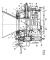
- the dosing machine conforms the invention comprises a frame 1 on which is mounted a hopper generally designated 2, vertical axis and intended to receive in bulk the products to be dosed then to put in box.
- the hopper 2 comprises a tank 3 delimited by a side wall, one end of which is closed by a bottom 4 horizontal and an opposite end has a collar 5 forming a support for a funnel 6 connected to the frame 1 by a hinge 7 to tilt around an axis horizontal perpendicular to the axis of the hopper 2 between a position in support against the support flange 5 of the tank 3 and a rearward position relative to to the tank 3.
- a scraper 8 is mounted inside the hopper 2 along a generator of the funnel 6.
- the scraper 8 has a lower end secured to a crown toothed 9 mounted to pivot on the flange 5 of the tank 3 under the action of a pinion, not visible on the figures, which is connected to an output shaft of an engine and which meshes with the ring gear 9 to move the scraper 8 according to a scanning movement of the inner face of the funnel 6.
- a mixing device can be Associated or substituted for the scraper 8 for brewing products in the funnel 6.
- Each transfer screw 10 extends horizontally at the bottom of the tank 3.
- Each transfer screw 10 possesses, by reference to a direction of transfer of the products, a downstream end passing through an opening 11 made in the side wall of the tank 3 for protrude from the tank 3 in a horizontal duct 12 which opens near the bottom 4 of the tank 3 and an upstream end secured to one end of a tree 13 passing through the side wall of the tank 3 and is received in a bearing 14 mounted outside the tank 3.
- the shafts 13 have opposite ends to the screws of transfer 10 which are equipped with 15 meshing gears with each other and one of the trees 13 is furthermore provided on this end of a 16 connected pulley via a belt 17 to a driving pulley 18 connected to an output shaft of a servomotor 19.
- Each conduit 12 has an enveloping inner surface the downstream end of the corresponding transfer screw 10.
- Axial grooves 20 are however provided in this inner surface to constitute an obstacle at the rotation of the products around the axis of the screw of transfer 10 so as to promote axial displacement of these products.
- Each conduit 12 has a free end which is in contact via sealing means with a body of a turn valve 21 which is also in contact via sealing means with an upper end of a metering roll 22 vertical axis (the sealing elements are for example here consist of annular joints partially nestable having complementary frustoconical shapes).
- the turning of the turning valve 21 delimits a channel bent at an angle of 90 °.
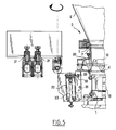
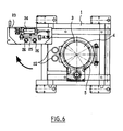
- Turning valves 21 are mounted on a support member 23 which is mounted on the frame 1 to be movable between an active position (shown in Figure 1) in which the body of turn valves 21 is against the ducts 12 and the metering rolls 22 and an inactive position (shown in Figures 5 and 6) in which the valves are separated from the ducts 12 and cylinders assay 22 to release access to them. Movement valves to turn 21 between the active position and the inactive position will be detailed later in the description. When the turning valves 21 are in position active, turning each turn valve 21 is movable between a feeding position of the cylinder assay 22 (shown in particular in FIG.
- the bent channel connects the conduit 12 to the cylinder 22 and a discharge position of the cylinder of dosage 22 in which the angled channel connects the cylinder dosing to a not shown support of a box to fill.
- the turns are driven between the position supply of the metering cylinders 22 and the position evacuation of the dosing cylinders 22 by via a jack 24 mounted on the support element 23 to actuate in a manner known in itself a rack and pinion 25 with which meshes gears 26 solidarity turns (see in particular Figure 6).
- the support element 23 is connected to the frame 1 by a platen 27 having an end connected to the frame 1 by via an elastic connection as here a buffer elastically deformable 28.
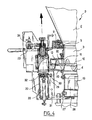
- the buffer elastically deformable 28 is arranged to allow a deflection angle of the plate 27, about a perpendicular axis to the axes of the conduits 12 and metering rolls 22, between the active position of the rotary valves 21 (shown in Figure 1) in which the plate 27 is horizontal and a first intermediate position (shown in Figure 3) in which the plate is tilted so that the body of the valves to turn 21 is spaced from the free ends of the ducts 12.
- Blocking of the plate 27 between these two positions is provided by an eccentric 29 mounted on the frame 1 to rotate around an axis parallel to the axis of movement and received in a light 30 formed in a solidarity plate 31 platinum and perpendicular to it.
- the light 30 is oblong and has a large perpendicular axis at plate 27 and has a width equal to a diameter eccentric 29.
- the eccentric 29 is arranged to be handled by an operator.
- the support element 23 is mounted on the plate 27 to tilt around an axis parallel to the axis of the ducts 12 between the first intermediate position (shown in Figure 3) and a second intermediate position (shown in Figure 4) in which the body turn valves 21 is slightly apart from the ends higher dosing cylinders 22.
- the support element 23 is also mounted on the plate 27 so as to pivot eccentrically around an axis perpendicular to the plate 27 between the second intermediate position of the rotary valves 21 (shown in Figure 4) and the inactive position (shown Figures 5 and 6).
- Each metering roll 22 has one end lower connected to the plate 27 to extend perpendicularly to this one.
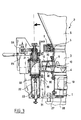
- Each dosing cylinder 22 receives a movable piston 32 between a low position suction and a high discharge position.
- the piston 32 is connected by a rod 33 through the bottom of the metering cylinder 22 and platen 27 with a slide 34 mounted on a slide 35 fixed under the plate 27 perpendicularly to this one.
- the slide 34 is connected via a connecting rod 36 to a crank pin 37 solidaire of an output shaft of a servomotor 38 also fixed under the plate 27 (see Figure 2).
- the length of the connecting rod 36 is adjustable to allow to adjust the position of the piston.
- the distance between the crankpin 37 and the output is adjustable, which would adjust the piston stroke to the quantity to be dosed.
- Rod 33 is connected to the slider 34 via a link patella 39.
- the operation of the dosing machine according to to the invention is similar in principle to that of known dosing machines.
- the servomotors 19 the transfer screws 10 and the servomotor 38 driving the pistons 32 can be parametered independently each other in order to precisely adjust on the one hand the quantity of product to be dosed and on the other possible compression of the product to be metering cylinder 22.
- valves 21 are also brought their active position to their inactive position.
- connection of the rotating valves 21 with frame 1 can have a different structure than the one described but, like this one, preferably to take off the valves to turn 21 ducts 12 and metering cylinders 21 respectively in one direction substantially axial ducts and a direction substantially axial cylinders during their movement from the active position to the inactive position.
- the angle between the conduit 12 and the cylinder of dosage 22 may be different from 90 °, it is then preferably greater than 90 ° but can be very slightly less than 90 °.
Landscapes
- Physics & Mathematics (AREA)
- Fluid Mechanics (AREA)
- General Physics & Mathematics (AREA)
- Feeding, Discharge, Calcimining, Fusing, And Gas-Generation Devices (AREA)
- Filling Or Emptying Of Bunkers, Hoppers, And Tanks (AREA)
- Basic Packing Technique (AREA)
Applications Claiming Priority (2)
| Application Number | Priority Date | Filing Date | Title |
|---|---|---|---|
| FR0210441 | 2002-08-21 | ||
| FR0210441A FR2843798B1 (fr) | 2002-08-21 | 2002-08-21 | Machine doseuse |
Publications (3)
| Publication Number | Publication Date |
|---|---|
| EP1391702A2 true EP1391702A2 (de) | 2004-02-25 |
| EP1391702A3 EP1391702A3 (de) | 2006-05-17 |
| EP1391702B1 EP1391702B1 (de) | 2009-03-18 |
Family
ID=30776051
Family Applications (1)
| Application Number | Title | Priority Date | Filing Date |
|---|---|---|---|
| EP03291963A Expired - Lifetime EP1391702B1 (de) | 2002-08-21 | 2003-08-05 | Dosiermaschine |
Country Status (4)
| Country | Link |
|---|---|
| US (1) | US7048157B2 (de) |
| EP (1) | EP1391702B1 (de) |
| DE (1) | DE60326681D1 (de) |
| FR (1) | FR2843798B1 (de) |
Cited By (3)
| Publication number | Priority date | Publication date | Assignee | Title |
|---|---|---|---|---|
| FR2972796A1 (fr) * | 2011-03-14 | 2012-09-21 | Celtech | Doseuse |
| CZ304499B6 (cs) * | 2013-03-28 | 2014-05-28 | Jiří Surý | Dávkovač kusového paliva, zejména pelet, pro zařízení pro vysokotlaké zplynování |
| CN108784266A (zh) * | 2017-04-26 | 2018-11-13 | 广东美的生活电器制造有限公司 | 螺杆及食物处理机 |
Families Citing this family (8)
| Publication number | Priority date | Publication date | Assignee | Title |
|---|---|---|---|---|
| US20080175094A1 (en) * | 2007-01-19 | 2008-07-24 | Bryan Henry | Solid Charging System |
| KR100845533B1 (ko) * | 2007-02-23 | 2008-07-10 | 주식회사 휴먼메디텍 | 플라즈마 멸균시스템의 액체 정량 공급장치 |
| FR2929703B1 (fr) * | 2008-04-08 | 2010-05-14 | Celtech | Doseuse a vis poussoirs multifilets pour le dosage et le remplissage dans des recipients de produits consistants et matieres molles. |
| FR3020677B1 (fr) * | 2014-04-30 | 2016-04-15 | Tremark Tech Inc | Machine doseuse a demontage automatise |
| FR3036482B1 (fr) * | 2015-05-22 | 2018-07-13 | Tremark | Machine de dosage a siphon a nettoyage en place ameliore |
| US10948336B2 (en) * | 2018-08-30 | 2021-03-16 | A. J. Antunes & Co. | Automated condiment dispensing system with precisely controlled dispensed quantities |
| US20210101188A1 (en) * | 2019-10-03 | 2021-04-08 | Flowtrend, Inc. | Full-flow sanitary valve |
| CN113559764A (zh) * | 2021-07-26 | 2021-10-29 | 广州科技职业技术大学 | 一种水性柔印油墨的配比装置和配比方法 |
Family Cites Families (9)
| Publication number | Priority date | Publication date | Assignee | Title |
|---|---|---|---|---|
| US2032163A (en) * | 1932-09-30 | 1936-02-25 | Ralph B Bagby | Filling machine |
| US2716510A (en) * | 1949-08-22 | 1955-08-30 | Benz & Hilgers Maschinenfabrik | Dosing apparatus |
| US4399932A (en) * | 1981-06-02 | 1983-08-23 | Guenter Zimmermann | Volumetric metering valve |
| US4566612A (en) * | 1983-09-15 | 1986-01-28 | Popsicle Industries, Inc. | Apparatus for dispensing flowable material |
| DE3734361C2 (de) * | 1987-10-10 | 2000-08-24 | Lieder Maschinenbau Gmbh & Co | Vorrichtung zum schonenden Verpacken |
| DE4036083C2 (de) * | 1990-04-05 | 1994-06-16 | Friedrich Bersch | Dosiereinrichtung |
| US5080148A (en) * | 1990-11-09 | 1992-01-14 | Fmc Corporation | Volume adjustment device for a filler |
| US5441173A (en) * | 1994-03-02 | 1995-08-15 | Continental Baking Company | Piston depositor |
| US5709322A (en) * | 1995-12-08 | 1998-01-20 | Acrison, Inc. | Dry solids metering system with means for self-emptying and quick-emptying/cleanout |
-
2002
- 2002-08-21 FR FR0210441A patent/FR2843798B1/fr not_active Expired - Fee Related
-
2003
- 2003-08-05 EP EP03291963A patent/EP1391702B1/de not_active Expired - Lifetime
- 2003-08-05 DE DE60326681T patent/DE60326681D1/de not_active Expired - Lifetime
- 2003-08-20 US US10/644,332 patent/US7048157B2/en not_active Expired - Lifetime
Cited By (3)
| Publication number | Priority date | Publication date | Assignee | Title |
|---|---|---|---|---|
| FR2972796A1 (fr) * | 2011-03-14 | 2012-09-21 | Celtech | Doseuse |
| CZ304499B6 (cs) * | 2013-03-28 | 2014-05-28 | Jiří Surý | Dávkovač kusového paliva, zejména pelet, pro zařízení pro vysokotlaké zplynování |
| CN108784266A (zh) * | 2017-04-26 | 2018-11-13 | 广东美的生活电器制造有限公司 | 螺杆及食物处理机 |
Also Published As
| Publication number | Publication date |
|---|---|
| DE60326681D1 (de) | 2009-04-30 |
| FR2843798B1 (fr) | 2005-02-11 |
| FR2843798A1 (fr) | 2004-02-27 |
| EP1391702A3 (de) | 2006-05-17 |
| EP1391702B1 (de) | 2009-03-18 |
| US7048157B2 (en) | 2006-05-23 |
| US20040035893A1 (en) | 2004-02-26 |
Similar Documents
| Publication | Publication Date | Title |
|---|---|---|
| EP1391702B1 (de) | Dosiermaschine | |
| WO2004074164A1 (fr) | Procede de vidange d’un conteneur souple renfermant un produit visqueux | |
| FR2843799A1 (fr) | Machine doseuse a barillet | |
| FR2608224A1 (fr) | Pompe a pistons axiaux | |
| FR2530583A1 (fr) | Dispositif de remplissage et de dosage de denrees alimentaires liquides et pateuses | |
| FR2605975A1 (fr) | Dispositif a element de fermeture pour un ajutage de remplissage d'une machine de remplissage | |
| FR2765856A1 (fr) | Dispositif de remplissage de recipients d'emballages par un produit fluide, pateux ou renfermant des particules | |
| EP1516836A1 (de) | Vorrichtung zum Entleeren von einem einen flachen Boden aufweisendem Silo | |
| FR3039137A1 (fr) | Machine doseuse a double volets cylindriques | |
| EP1100724A1 (de) | Abgabevorrichtung, insbesondere für dosiervorrichtung von verpackungsmaschinen, und mit dergleichen vorrichtung versehene dosiervorrichtung | |
| EP1801017B1 (de) | Vorrichtung zum Befüllen von Behältern mit einer Einrichtung zum Regeln der Höhe | |
| EP0169759B1 (de) | Ladegerät für Siloentnahme- und -verteilergeräte | |
| FR3036482A1 (fr) | Machine de dosage a siphon a nettoyage en place ameliore | |
| WO2006040449A1 (fr) | Dispositif de preparation de dechets a recycler | |
| FR2851764A1 (fr) | Dispositif de remplissage de recipients | |
| FR3148383A1 (fr) | Dispositif de broyage d’un produit pâteux ou en poudre et en suspension | |
| EP2887826B1 (de) | Verbesserte anlage zur herstellung eines elements aus restrukturiertem fleisch | |
| EP3532389A1 (de) | Verfahren und vorrichtungen zum befüllen von töpfen, topfverpackungslinien | |
| FR3145149A1 (fr) | Système d’écoulement comportant un tube rotatif pour une machine de dosage | |
| FR2535942A1 (fr) | Diviseuse-peseuse, notamment pour le debitage de volumes egaux de pate a pain | |
| FR2571927A1 (fr) | Entrainement pour le dispositif d'alimentation du produit recolte sur des presses a balles | |
| FR2655311A1 (fr) | Machine pour doser une quantite predeterminee de produits pharmaceutiques pulverulents dans un conteneur. | |
| FR2819146A1 (fr) | Machine portee permettant le chargement, le melange et la distribution de produits divers | |
| WO2001083304A1 (fr) | Machine de dosage et de remplissage de produits liquides ou pateux | |
| EP2940436A1 (de) | Dosiermaschine mit automatisierter demontage |
Legal Events
| Date | Code | Title | Description |
|---|---|---|---|
| PUAI | Public reference made under article 153(3) epc to a published international application that has entered the european phase |
Free format text: ORIGINAL CODE: 0009012 |
|
| AK | Designated contracting states |
Kind code of ref document: A2 Designated state(s): AT BE BG CH CY CZ DE DK EE ES FI FR GB GR HU IE IT LI LU MC NL PT RO SE SI SK TR |
|
| AX | Request for extension of the european patent |
Extension state: AL LT LV MK |
|
| PUAL | Search report despatched |
Free format text: ORIGINAL CODE: 0009013 |
|
| AK | Designated contracting states |
Kind code of ref document: A3 Designated state(s): AT BE BG CH CY CZ DE DK EE ES FI FR GB GR HU IE IT LI LU MC NL PT RO SE SI SK TR |
|
| AX | Request for extension of the european patent |
Extension state: AL LT LV MK |
|
| RIC1 | Information provided on ipc code assigned before grant |
Ipc: G01F 13/00 20060101ALI20060329BHEP Ipc: G01F 11/02 20060101AFI20031220BHEP |
|
| 17P | Request for examination filed |
Effective date: 20061024 |
|
| 17Q | First examination report despatched |
Effective date: 20061205 |
|
| AKX | Designation fees paid |
Designated state(s): DE ES FR IT |
|
| GRAP | Despatch of communication of intention to grant a patent |
Free format text: ORIGINAL CODE: EPIDOSNIGR1 |
|
| GRAS | Grant fee paid |
Free format text: ORIGINAL CODE: EPIDOSNIGR3 |
|
| GRAA | (expected) grant |
Free format text: ORIGINAL CODE: 0009210 |
|
| AK | Designated contracting states |
Kind code of ref document: B1 Designated state(s): DE ES FR IT |
|
| REF | Corresponds to: |
Ref document number: 60326681 Country of ref document: DE Date of ref document: 20090430 Kind code of ref document: P |
|
| PG25 | Lapsed in a contracting state [announced via postgrant information from national office to epo] |
Ref country code: ES Free format text: LAPSE BECAUSE OF FAILURE TO SUBMIT A TRANSLATION OF THE DESCRIPTION OR TO PAY THE FEE WITHIN THE PRESCRIBED TIME-LIMIT Effective date: 20090629 |
|
| PLBE | No opposition filed within time limit |
Free format text: ORIGINAL CODE: 0009261 |
|
| STAA | Information on the status of an ep patent application or granted ep patent |
Free format text: STATUS: NO OPPOSITION FILED WITHIN TIME LIMIT |
|
| 26N | No opposition filed |
Effective date: 20091221 |
|
| PG25 | Lapsed in a contracting state [announced via postgrant information from national office to epo] |
Ref country code: IT Free format text: LAPSE BECAUSE OF FAILURE TO SUBMIT A TRANSLATION OF THE DESCRIPTION OR TO PAY THE FEE WITHIN THE PRESCRIBED TIME-LIMIT Effective date: 20090318 |
|
| REG | Reference to a national code |
Ref country code: DE Ref legal event code: R082 Ref document number: 60326681 Country of ref document: DE Representative=s name: SCHAUMBURG & PARTNER PATENTANWAELTE GBR, DE Ref country code: DE Ref legal event code: R082 Ref document number: 60326681 Country of ref document: DE Representative=s name: SCHAUMBURG UND PARTNER PATENTANWAELTE MBB, DE |
|
| REG | Reference to a national code |
Ref country code: FR Ref legal event code: PLFP Year of fee payment: 14 |
|
| REG | Reference to a national code |
Ref country code: DE Ref legal event code: R082 Ref document number: 60326681 Country of ref document: DE Representative=s name: SCHAUMBURG UND PARTNER PATENTANWAELTE MBB, DE Ref country code: DE Ref legal event code: R081 Ref document number: 60326681 Country of ref document: DE Owner name: TREMARK, FR Free format text: FORMER OWNER: TREMARK TECHNOLOGIES INC., MT. ST. HILAIRE, QUEBEC, CA |
|
| REG | Reference to a national code |
Ref country code: FR Ref legal event code: TP Owner name: WEATHERFORD TECHNOLOGY HOLDINGS, LLC, US Effective date: 20170614 |
|
| REG | Reference to a national code |
Ref country code: FR Ref legal event code: PLFP Year of fee payment: 15 |
|
| PGFP | Annual fee paid to national office [announced via postgrant information from national office to epo] |
Ref country code: DE Payment date: 20190822 Year of fee payment: 17 |
|
| REG | Reference to a national code |
Ref country code: DE Ref legal event code: R119 Ref document number: 60326681 Country of ref document: DE |
|
| PG25 | Lapsed in a contracting state [announced via postgrant information from national office to epo] |
Ref country code: DE Free format text: LAPSE BECAUSE OF NON-PAYMENT OF DUE FEES Effective date: 20210302 |
|
| PGFP | Annual fee paid to national office [announced via postgrant information from national office to epo] |
Ref country code: FR Payment date: 20220823 Year of fee payment: 20 |