EP1391584A2 - Turbolader mit variabler Turbinengeometrie - Google Patents
Turbolader mit variabler Turbinengeometrie Download PDFInfo
- Publication number
- EP1391584A2 EP1391584A2 EP03018579A EP03018579A EP1391584A2 EP 1391584 A2 EP1391584 A2 EP 1391584A2 EP 03018579 A EP03018579 A EP 03018579A EP 03018579 A EP03018579 A EP 03018579A EP 1391584 A2 EP1391584 A2 EP 1391584A2
- Authority
- EP
- European Patent Office
- Prior art keywords
- adjusting
- levers
- plane
- guide vane
- level
- Prior art date
- Legal status (The legal status is an assumption and is not a legal conclusion. Google has not performed a legal analysis and makes no representation as to the accuracy of the status listed.)
- Granted
Links
- 238000002485 combustion reaction Methods 0.000 claims abstract description 5
- 230000001419 dependent effect Effects 0.000 description 2
- 230000001105 regulatory effect Effects 0.000 description 2
- 238000005096 rolling process Methods 0.000 description 2
- 238000010276 construction Methods 0.000 description 1
- 238000009434 installation Methods 0.000 description 1
Images
Classifications
-
- F—MECHANICAL ENGINEERING; LIGHTING; HEATING; WEAPONS; BLASTING
- F02—COMBUSTION ENGINES; HOT-GAS OR COMBUSTION-PRODUCT ENGINE PLANTS
- F02C—GAS-TURBINE PLANTS; AIR INTAKES FOR JET-PROPULSION PLANTS; CONTROLLING FUEL SUPPLY IN AIR-BREATHING JET-PROPULSION PLANTS
- F02C6/00—Plural gas-turbine plants; Combinations of gas-turbine plants with other apparatus; Adaptations of gas-turbine plants for special use
- F02C6/04—Gas-turbine plants providing heated or pressurised working fluid for other apparatus, e.g. without mechanical power output
- F02C6/10—Gas-turbine plants providing heated or pressurised working fluid for other apparatus, e.g. without mechanical power output supplying working fluid to a user, e.g. a chemical process, which returns working fluid to a turbine of the plant
- F02C6/12—Turbochargers, i.e. plants for augmenting mechanical power output of internal-combustion piston engines by increase of charge pressure
-
- F—MECHANICAL ENGINEERING; LIGHTING; HEATING; WEAPONS; BLASTING
- F01—MACHINES OR ENGINES IN GENERAL; ENGINE PLANTS IN GENERAL; STEAM ENGINES
- F01D—NON-POSITIVE DISPLACEMENT MACHINES OR ENGINES, e.g. STEAM TURBINES
- F01D17/00—Regulating or controlling by varying flow
- F01D17/10—Final actuators
- F01D17/12—Final actuators arranged in stator parts
- F01D17/14—Final actuators arranged in stator parts varying effective cross-sectional area of nozzles or guide conduits
- F01D17/16—Final actuators arranged in stator parts varying effective cross-sectional area of nozzles or guide conduits by means of nozzle vanes
- F01D17/165—Final actuators arranged in stator parts varying effective cross-sectional area of nozzles or guide conduits by means of nozzle vanes for radial flow, i.e. the vanes turning around axes which are essentially parallel to the rotor centre line
Definitions
- the invention relates to a turbocharger with a variable turbine geometry Internal combustion engine, in particular a motor vehicle, with one Guide vane carrier guide vanes arranged pivotably in a first plane Turbine, each of which is assigned a first adjusting lever, and with one Adjustment ring, which is in a second plane axially spaced from the first plane is arranged and an angular position of the by rotation relative to the guide vane carrier Guide vanes adjusted collectively for all guide vanes relative to a flow direction, according to the preamble of claim 1.
- a turbocharger is known from DE 100 13 335 A1, in which the adjusting ring on its Outside surface is mounted on rolling elements. These rolling elements are as on a support ring pivoted, single-armed levers. With one over one External control initiated rotation of the adjusting ring roll in the grooves guided sections of the outer surface of the collar while swiveling the one-armed lever on a groove base. This is said to be a self-locking of the Avoid the collar during a rotary movement.
- EP 0 160 460 A2 describes a turbocharger with an adjustable turbine geometry known, in which the adjusting ring is mounted by means of rollers. The roles are on one of the End faces of the adjusting ring arranged and project beyond an outer circumference of the Adjustment ring in the radial direction.
- the collar is in an annular recess rotatably arranged, the rollers in an expansion of the recess in the axial Grab direction.
- the bearings for the collar described above are mechanical complex, cost-intensive, require a large amount of installation space and have a high Number of individual parts connected.
- the invention has for its object a turbocharger of the above type to improve its mechanical structure.
- the adjusting ring has one each second adjusting lever is connected to the first adjusting levers, the first Adjusting lever axially spaced from the first and second levels in a third level are arranged and designed in this way and in the radial direction the adjusting ring cover that the first adjusting lever the adjusting ring between itself and the Guide the guide vane carrier.
- the second adjustment levers are on one Projection of the adjusting ring with this pivotable and on one of the adjusting ring opposite end each pivotally connected to one of the first adjusting levers.
- the first adjusting levers are expediently each on one of the second End facing away from the adjusting levers is connected in a rotationally fixed manner to a guide vane.
- the second adjustment levers are preferably axially spaced from the third plane of the first adjusting lever arranged in a fourth level, the second adjusting lever are arranged such that the fourth level of the second lever between the second level of the adjusting ring and the third level of the first adjusting lever or the third level of the first adjusting lever between the second level of the adjusting ring and fourth level of the second adjusting lever is arranged.
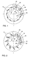
- FIG. 1 and 2 schematically show a preferred embodiment of a turbine part of an otherwise not shown exhaust gas turbocharger of an internal combustion engine.
- a guide vane carrier 10 On a guide vane carrier 10 are pivotally mounted about an axis 12 and in a first plane axially spaced from the guide vane carrier 10 Guide vanes 14 are provided. The pivot axes 12 of the guide vanes 14 are fixed on the vane carrier 10 is arranged.
- Each guide vane 14 is a first adjustment lever 16 assigned, which is rotatably connected to the respective guide vane 14, wherein all first adjusting levers 16 in an axially from the first plane of the guide vane carrier 10 spaced second level are arranged and in the radial direction over the Adjustment ring 22 protrude.
- Ring means here and below a direction with respect to one Axis of rotation 24 of the turbine is meant. This results in a certain overlap between the first adjusting levers 16 and the adjusting ring 22 Adjustment ring 22 between the first adjustment levers 16 and the guide vane carrier 10 axially guided.
- the adjusting ring 22 is connected to the first adjusting levers 16 via a respective second one Adjusting lever 26 connected, each first adjusting lever 16 via a respective one second adjusting lever 26 is connected to the adjusting ring 22.
- the second Adjusting levers 26 are facing away from the first adjusting levers 16 Ends each on a projection 28 of the adjusting ring 22 with this around an axis 30 pivotally connected.
- the second adjustment lever 26 are also with their from Adjustment ring 22 opposite ends each with a first adjustment ring 16 by one Axis 32 pivotally connected.
- the adjusting ring 22 is arranged pivotably with respect to the guide vane carrier 10, a pivoting of the adjusting ring 22 with respect to the guide vane carrier 10 for pivoting the first and second adjusting levers 16, 26 about the respective ones Axes 12, 30 and 32 conditional. With the adjustment levers 16 and 26 also pivot respective guide vanes 14 about the axes 12. Depending on the position of the guide vanes 14 a pressure or a compressor output is regulated with respect to the direction of flow.
- Fig. 1 shows an "open" position of the guide vanes 14
- FIG. 2 shows one "Closed" position of the guide vanes 14, which is achieved in that starting from the position shown in FIG.
- the second adjusting levers 26 are shown in the exemplary embodiment shown in FIG a fourth plane arranged axially from the third plane of the first Adjusting lever 16 and the second level of the adjusting ring 22 are arranged in such a way that the third level of the first lever 16 between the second level of Adjustment ring 22 and the fourth level of the second adjustment lever 26 is arranged.
- the Guide vanes 14 and the adjusting ring 22 are in the illustrated embodiment opposite sides of the guide vane carrier 10 are arranged.
Landscapes
- Engineering & Computer Science (AREA)
- Chemical & Material Sciences (AREA)
- Mechanical Engineering (AREA)
- General Engineering & Computer Science (AREA)
- Chemical Kinetics & Catalysis (AREA)
- General Chemical & Material Sciences (AREA)
- Combustion & Propulsion (AREA)
- Supercharger (AREA)
Abstract
Description
- Fig. 1
- eine bevorzugte Ausführungsform einer erfindungsgemäß ausgebildeten Turbine mit Leitschaufeln eines Abgasturboladers bei offener Stellung der Leitschaufeln in Schnittansicht und
- Fig. 2
- die bevorzugte Ausführungsform einer erfindungsgemäß ausgebildeten Turbine mit Leitschaufeln eines Abgasturboladers gemäß Fig. 1 bei geschlossener Stellung der Leitschaufeln in Schnittansicht.
Claims (6)
- Turbolader mit variabler Turbinengeometrie einer Brennkraftmaschine, insbesondere eines Kraftfahrzeuges, mit an einem Leitschaufelträger (10) in einer ersten Ebene schwenkbar angeordneten Leitschaufeln (14) einer Turbine, denen jeweils ein erster Verstellhebel (16) zugeordnet ist, und mit einem Verstellring (22), welcher in einer axial von der ersten Ebene des Leitschaufelträgers (10) beabstandeten zweiten Ebene angeordnet ist und durch Drehung relativ zum Leitschaufelträger (10) eine Winkelstellung der Leitschaufeln (14) relativ zu einer Strömungsrichtung kollektiv für alle Leitschaufeln (14) verstellt, dadurch gekennzeichnet, daß der Verstellring (22) über jeweils einen zweiten Verstellhebel (26) mit den ersten Verstellhebeln (16) verbunden ist, wobei die ersten Verstellhebel (16) axial von der ersten Ebene des Leitschaufelträgers (10) und der zweiten Ebene des Verstellringes (22) beabstandet in einer dritten Ebene derart angeordnet und ausgebildet sind sowie in radialer Richtung den Verstellring (22) überdecken, daß die ersten Verstellhebel (16) den Verstellring (22) zwischen sich und dem Leitschaufelträger (10) führen.
- Turbolader nach Anspruch 1, dadurch gekennzeichnet, daß die zweiten Verstellhebel an einem Vorsprung des Verstellringes mit diesem schwenkbar verbunden sind.
- Turbolader nach Anspruch 1 oder 2, dadurch gekennzeichnet, daß die zweiten Verstellhebel (26) an einem vom Verstellring (22) abgewandten Ende jeweils mit einem der ersten Verstellhebel (16) schwenkbar verbunden sind.
- Turbolader nach wenigstens einem der vorhergehenden Ansprüche, dadurch gekennzeichnet, daß die ersten Verstellhebel (16) jeweils an einem von den zweiten Verstellhebeln (26) abgewandten Ende drehfest mit einer Leitschaufel (14) verbunden sind.
- Turbolader nach wenigstens einem der vorhergehenden Ansprüche, dadurch gekennzeichnet, daß die zweiten Verstellhebel (26) axial beabstandet von der dritten Ebene der ersten Verstellhebel (16) in einer vierten Ebene angeordnet sind.
- Turbolader nach Anspruch 5, dadurch gekennzeichnet, daß die zweiten Verstellhebel (26) derart angeordnet sind, daß die vierte Ebene der zweiten Verstellhebel (26) zwischen der zweiten Ebene des Verstellrings (22) und der dritten Ebene der ersten Verstellhebel (16) oder die dritte Ebene der ersten Verstellhebel (16) zwischen der zweiten Ebene des Verstellrings (22) und vierten Ebene der zweiten Verstellhebel (26) angeordnet ist.
Applications Claiming Priority (2)
| Application Number | Priority Date | Filing Date | Title |
|---|---|---|---|
| DE10238413 | 2002-08-22 | ||
| DE10238413A DE10238413A1 (de) | 2002-08-22 | 2002-08-22 | Turbolader mit variabler Turbinengeometrie |
Publications (3)
| Publication Number | Publication Date |
|---|---|
| EP1391584A2 true EP1391584A2 (de) | 2004-02-25 |
| EP1391584A3 EP1391584A3 (de) | 2005-10-12 |
| EP1391584B1 EP1391584B1 (de) | 2010-04-28 |
Family
ID=30775506
Family Applications (1)
| Application Number | Title | Priority Date | Filing Date |
|---|---|---|---|
| EP03018579A Expired - Lifetime EP1391584B1 (de) | 2002-08-22 | 2003-08-18 | Turbolader mit variabler Turbinengeometrie |
Country Status (3)
| Country | Link |
|---|---|
| EP (1) | EP1391584B1 (de) |
| AT (1) | ATE466179T1 (de) |
| DE (2) | DE10238413A1 (de) |
Cited By (2)
| Publication number | Priority date | Publication date | Assignee | Title |
|---|---|---|---|---|
| CN102966381A (zh) * | 2011-08-31 | 2013-03-13 | 诺沃皮尼奥内有限公司 | 用于涡轮膨胀器应用的紧凑的igv |
| EP2236792A3 (de) * | 2009-03-31 | 2014-07-23 | Nuovo Pignone S.p.A. | Düseneinstellmechanismus und -verfahren |
Families Citing this family (1)
| Publication number | Priority date | Publication date | Assignee | Title |
|---|---|---|---|---|
| DE102013224572A1 (de) | 2013-11-29 | 2015-06-03 | Bosch Mahle Turbo Systems Gmbh & Co. Kg | Abgasturbolader, insbesondere für ein Kraftfahrzeug |
Family Cites Families (5)
| Publication number | Priority date | Publication date | Assignee | Title |
|---|---|---|---|---|
| US1951640A (en) * | 1929-11-30 | 1934-03-20 | Frederick A Allner | Dual use hydraulic machine |
| US4741666A (en) * | 1985-12-23 | 1988-05-03 | Ishikawajima-Harima Jukogyo Kabushiki Kaisha | Variable displacement turbocharger |
| IT1217437B (it) * | 1988-04-21 | 1990-03-22 | Nuovo Pignone Spa | Sistema perfezionato di registrazione in posizione degli ugelli orientabili di una turbina a gas |
| DE19717855C2 (de) * | 1997-04-23 | 2000-11-16 | Ver Energiewerke Ag | Einrichtung zum Verstellen der Leitschaufeln von Strömungsmaschinen, insbesondere von Wasserturbinen |
| JP4033978B2 (ja) * | 1998-08-21 | 2008-01-16 | 株式会社アキタファインブランキング | 可変ベーン型ターボチャージャ用タービンフレーム |
-
2002
- 2002-08-22 DE DE10238413A patent/DE10238413A1/de not_active Withdrawn
-
2003
- 2003-08-18 EP EP03018579A patent/EP1391584B1/de not_active Expired - Lifetime
- 2003-08-18 DE DE50312657T patent/DE50312657D1/de not_active Expired - Lifetime
- 2003-08-18 AT AT03018579T patent/ATE466179T1/de not_active IP Right Cessation
Cited By (4)
| Publication number | Priority date | Publication date | Assignee | Title |
|---|---|---|---|---|
| EP2236792A3 (de) * | 2009-03-31 | 2014-07-23 | Nuovo Pignone S.p.A. | Düseneinstellmechanismus und -verfahren |
| CN102966381A (zh) * | 2011-08-31 | 2013-03-13 | 诺沃皮尼奥内有限公司 | 用于涡轮膨胀器应用的紧凑的igv |
| CN102966381B (zh) * | 2011-08-31 | 2016-06-29 | 诺沃皮尼奥内有限公司 | 用于涡轮膨胀器应用的紧凑的igv |
| US9464533B2 (en) | 2011-08-31 | 2016-10-11 | Nuovo Pignone S.P.A | Compact IGV for turboexpander application |
Also Published As
| Publication number | Publication date |
|---|---|
| EP1391584B1 (de) | 2010-04-28 |
| DE10238413A1 (de) | 2004-03-04 |
| DE50312657D1 (de) | 2010-06-10 |
| ATE466179T1 (de) | 2010-05-15 |
| EP1391584A3 (de) | 2005-10-12 |
Similar Documents
| Publication | Publication Date | Title |
|---|---|---|
| EP2209969B1 (de) | Ladeeinrichtung | |
| EP2002127B1 (de) | Vordrall-leitvorrichtung | |
| DE102010038185B4 (de) | Düseneinrichtung eines Turboladers variabler Geometrie | |
| DE19815112B4 (de) | Anordnung zur variablen Ventilzeitsteuerung und Ventilbetätigung | |
| DE102008007670B4 (de) | Steuerring für VTG | |
| DE112010004597B4 (de) | Turbolader mit variabler Turbinengeometrie | |
| EP3421741B1 (de) | Variabler ventiltrieb | |
| EP1347154B1 (de) | Ventilsteuerung zur Einstellung des Hubes von Ventilen in einer Brennkraftmaschine | |
| DE10351223B4 (de) | Nockenwellenverstelleinrichtung für Fahrzeuge, vorzugsweise für Kraftfahrzeuge | |
| EP1520959B1 (de) | Turbokompressor mit verstellbaren Leitschaufeln | |
| DE112013001527B4 (de) | Abgasturbolader mit variabler Turbinengeometrie | |
| WO2008155400A1 (de) | Antrieb für vordrall-leitvorrichtung | |
| DE10238412A1 (de) | Turbolader mit variabler Turbinengeometrie | |
| DE102004037082A1 (de) | Abgasturbolader mit variabler Turbinengeometrie | |
| EP1391584A2 (de) | Turbolader mit variabler Turbinengeometrie | |
| DE20220138U1 (de) | Ventiltrieb mit Nocken zur variablen Betätigung von Ventilen für Verbrennungsmotoren | |
| DE102007022356A1 (de) | Ladeeinrichtung | |
| DE10313167B4 (de) | Leitschaufelverstellung für Turbolader mit variabler Turbinengeometrie | |
| EP1391585B1 (de) | Turbolader mit variabler Turbinengeometrie | |
| EP1593880B1 (de) | Verstellwelle eines hubvariablen Ventiltriebs | |
| DE102004023282A1 (de) | Abgasturbolader für eine Brennkraftmaschine mit variabler Turbinengeometrie | |
| EP2071134A2 (de) | Variable Turbinengeometrie | |
| DE102010054914A1 (de) | Leiteinrichtung für eine Fluidenergiemaschine, insbesondere für einen Abgasturbolader | |
| DE102004023211A1 (de) | Abgasturbolader für eine Brennkraftmaschine mit variabler Turbinengeometrie | |
| DE102014001034A1 (de) | Strömungsmaschine |
Legal Events
| Date | Code | Title | Description |
|---|---|---|---|
| PUAI | Public reference made under article 153(3) epc to a published international application that has entered the european phase |
Free format text: ORIGINAL CODE: 0009012 |
|
| AK | Designated contracting states |
Kind code of ref document: A2 Designated state(s): AT BE BG CH CY CZ DE DK EE ES FI FR GB GR HU IE IT LI LU MC NL PT RO SE SI SK TR |
|
| AX | Request for extension of the european patent |
Extension state: AL LT LV MK |
|
| RIN1 | Information on inventor provided before grant (corrected) |
Inventor name: BAAR, ROLAND, DR. |
|
| PUAL | Search report despatched |
Free format text: ORIGINAL CODE: 0009013 |
|
| AK | Designated contracting states |
Kind code of ref document: A3 Designated state(s): AT BE BG CH CY CZ DE DK EE ES FI FR GB GR HU IE IT LI LU MC NL PT RO SE SI SK TR |
|
| AX | Request for extension of the european patent |
Extension state: AL LT LV MK |
|
| RIC1 | Information provided on ipc code assigned before grant |
Ipc: 7F 02C 6/12 A Ipc: 7F 01D 17/16 B |
|
| 17P | Request for examination filed |
Effective date: 20060412 |
|
| AKX | Designation fees paid |
Designated state(s): AT BE BG CH CY CZ DE DK EE ES FI FR GB GR HU IE IT LI LU MC NL PT RO SE SI SK TR |
|
| 17Q | First examination report despatched |
Effective date: 20060728 |
|
| GRAP | Despatch of communication of intention to grant a patent |
Free format text: ORIGINAL CODE: EPIDOSNIGR1 |
|
| GRAS | Grant fee paid |
Free format text: ORIGINAL CODE: EPIDOSNIGR3 |
|
| GRAA | (expected) grant |
Free format text: ORIGINAL CODE: 0009210 |
|
| AK | Designated contracting states |
Kind code of ref document: B1 Designated state(s): AT BE BG CH CY CZ DE DK EE ES FI FR GB GR HU IE IT LI LU MC NL PT RO SE SI SK TR |
|
| REG | Reference to a national code |
Ref country code: GB Ref legal event code: FG4D Free format text: NOT ENGLISH |
|
| REG | Reference to a national code |
Ref country code: CH Ref legal event code: EP |
|
| REG | Reference to a national code |
Ref country code: IE Ref legal event code: FG4D Free format text: LANGUAGE OF EP DOCUMENT: GERMAN |
|
| REF | Corresponds to: |
Ref document number: 50312657 Country of ref document: DE Date of ref document: 20100610 Kind code of ref document: P |
|
| REG | Reference to a national code |
Ref country code: NL Ref legal event code: VDEP Effective date: 20100428 |
|
| PG25 | Lapsed in a contracting state [announced via postgrant information from national office to epo] |
Ref country code: NL Free format text: LAPSE BECAUSE OF FAILURE TO SUBMIT A TRANSLATION OF THE DESCRIPTION OR TO PAY THE FEE WITHIN THE PRESCRIBED TIME-LIMIT Effective date: 20100428 Ref country code: ES Free format text: LAPSE BECAUSE OF FAILURE TO SUBMIT A TRANSLATION OF THE DESCRIPTION OR TO PAY THE FEE WITHIN THE PRESCRIBED TIME-LIMIT Effective date: 20100808 Ref country code: SE Free format text: LAPSE BECAUSE OF FAILURE TO SUBMIT A TRANSLATION OF THE DESCRIPTION OR TO PAY THE FEE WITHIN THE PRESCRIBED TIME-LIMIT Effective date: 20100428 |
|
| REG | Reference to a national code |
Ref country code: IE Ref legal event code: FD4D |
|
| PG25 | Lapsed in a contracting state [announced via postgrant information from national office to epo] |
Ref country code: FI Free format text: LAPSE BECAUSE OF FAILURE TO SUBMIT A TRANSLATION OF THE DESCRIPTION OR TO PAY THE FEE WITHIN THE PRESCRIBED TIME-LIMIT Effective date: 20100428 Ref country code: SI Free format text: LAPSE BECAUSE OF FAILURE TO SUBMIT A TRANSLATION OF THE DESCRIPTION OR TO PAY THE FEE WITHIN THE PRESCRIBED TIME-LIMIT Effective date: 20100428 |
|
| PG25 | Lapsed in a contracting state [announced via postgrant information from national office to epo] |
Ref country code: GR Free format text: LAPSE BECAUSE OF FAILURE TO SUBMIT A TRANSLATION OF THE DESCRIPTION OR TO PAY THE FEE WITHIN THE PRESCRIBED TIME-LIMIT Effective date: 20100729 Ref country code: CY Free format text: LAPSE BECAUSE OF FAILURE TO SUBMIT A TRANSLATION OF THE DESCRIPTION OR TO PAY THE FEE WITHIN THE PRESCRIBED TIME-LIMIT Effective date: 20100428 |
|
| PG25 | Lapsed in a contracting state [announced via postgrant information from national office to epo] |
Ref country code: IE Free format text: LAPSE BECAUSE OF FAILURE TO SUBMIT A TRANSLATION OF THE DESCRIPTION OR TO PAY THE FEE WITHIN THE PRESCRIBED TIME-LIMIT Effective date: 20100428 Ref country code: DK Free format text: LAPSE BECAUSE OF FAILURE TO SUBMIT A TRANSLATION OF THE DESCRIPTION OR TO PAY THE FEE WITHIN THE PRESCRIBED TIME-LIMIT Effective date: 20100428 Ref country code: PT Free format text: LAPSE BECAUSE OF FAILURE TO SUBMIT A TRANSLATION OF THE DESCRIPTION OR TO PAY THE FEE WITHIN THE PRESCRIBED TIME-LIMIT Effective date: 20100830 Ref country code: EE Free format text: LAPSE BECAUSE OF FAILURE TO SUBMIT A TRANSLATION OF THE DESCRIPTION OR TO PAY THE FEE WITHIN THE PRESCRIBED TIME-LIMIT Effective date: 20100428 |
|
| BERE | Be: lapsed |
Owner name: VOLKSWAGEN AG Effective date: 20100831 |
|
| PG25 | Lapsed in a contracting state [announced via postgrant information from national office to epo] |
Ref country code: SK Free format text: LAPSE BECAUSE OF FAILURE TO SUBMIT A TRANSLATION OF THE DESCRIPTION OR TO PAY THE FEE WITHIN THE PRESCRIBED TIME-LIMIT Effective date: 20100428 Ref country code: CZ Free format text: LAPSE BECAUSE OF FAILURE TO SUBMIT A TRANSLATION OF THE DESCRIPTION OR TO PAY THE FEE WITHIN THE PRESCRIBED TIME-LIMIT Effective date: 20100428 Ref country code: RO Free format text: LAPSE BECAUSE OF FAILURE TO SUBMIT A TRANSLATION OF THE DESCRIPTION OR TO PAY THE FEE WITHIN THE PRESCRIBED TIME-LIMIT Effective date: 20100428 |
|
| PLBE | No opposition filed within time limit |
Free format text: ORIGINAL CODE: 0009261 |
|
| STAA | Information on the status of an ep patent application or granted ep patent |
Free format text: STATUS: NO OPPOSITION FILED WITHIN TIME LIMIT |
|
| PG25 | Lapsed in a contracting state [announced via postgrant information from national office to epo] |
Ref country code: MC Free format text: LAPSE BECAUSE OF NON-PAYMENT OF DUE FEES Effective date: 20100831 Ref country code: IT Free format text: LAPSE BECAUSE OF FAILURE TO SUBMIT A TRANSLATION OF THE DESCRIPTION OR TO PAY THE FEE WITHIN THE PRESCRIBED TIME-LIMIT Effective date: 20100428 |
|
| REG | Reference to a national code |
Ref country code: CH Ref legal event code: PL |
|
| 26N | No opposition filed |
Effective date: 20110131 |
|
| GBPC | Gb: european patent ceased through non-payment of renewal fee |
Effective date: 20100818 |
|
| PG25 | Lapsed in a contracting state [announced via postgrant information from national office to epo] |
Ref country code: CH Free format text: LAPSE BECAUSE OF NON-PAYMENT OF DUE FEES Effective date: 20100831 Ref country code: LI Free format text: LAPSE BECAUSE OF NON-PAYMENT OF DUE FEES Effective date: 20100831 |
|
| PG25 | Lapsed in a contracting state [announced via postgrant information from national office to epo] |
Ref country code: BE Free format text: LAPSE BECAUSE OF NON-PAYMENT OF DUE FEES Effective date: 20100831 |
|
| PG25 | Lapsed in a contracting state [announced via postgrant information from national office to epo] |
Ref country code: GB Free format text: LAPSE BECAUSE OF NON-PAYMENT OF DUE FEES Effective date: 20100818 |
|
| PG25 | Lapsed in a contracting state [announced via postgrant information from national office to epo] |
Ref country code: AT Free format text: LAPSE BECAUSE OF NON-PAYMENT OF DUE FEES Effective date: 20100818 |
|
| PG25 | Lapsed in a contracting state [announced via postgrant information from national office to epo] |
Ref country code: BG Free format text: LAPSE BECAUSE OF FAILURE TO SUBMIT A TRANSLATION OF THE DESCRIPTION OR TO PAY THE FEE WITHIN THE PRESCRIBED TIME-LIMIT Effective date: 20100428 Ref country code: HU Free format text: LAPSE BECAUSE OF FAILURE TO SUBMIT A TRANSLATION OF THE DESCRIPTION OR TO PAY THE FEE WITHIN THE PRESCRIBED TIME-LIMIT Effective date: 20101029 Ref country code: LU Free format text: LAPSE BECAUSE OF NON-PAYMENT OF DUE FEES Effective date: 20100818 |
|
| PG25 | Lapsed in a contracting state [announced via postgrant information from national office to epo] |
Ref country code: TR Free format text: LAPSE BECAUSE OF FAILURE TO SUBMIT A TRANSLATION OF THE DESCRIPTION OR TO PAY THE FEE WITHIN THE PRESCRIBED TIME-LIMIT Effective date: 20100428 |
|
| PG25 | Lapsed in a contracting state [announced via postgrant information from national office to epo] |
Ref country code: BG Free format text: LAPSE BECAUSE OF FAILURE TO SUBMIT A TRANSLATION OF THE DESCRIPTION OR TO PAY THE FEE WITHIN THE PRESCRIBED TIME-LIMIT Effective date: 20100728 |
|
| REG | Reference to a national code |
Ref country code: FR Ref legal event code: PLFP Year of fee payment: 13 |
|
| PGFP | Annual fee paid to national office [announced via postgrant information from national office to epo] |
Ref country code: DE Payment date: 20150831 Year of fee payment: 13 |
|
| PGFP | Annual fee paid to national office [announced via postgrant information from national office to epo] |
Ref country code: FR Payment date: 20150831 Year of fee payment: 13 |
|
| REG | Reference to a national code |
Ref country code: DE Ref legal event code: R082 Ref document number: 50312657 Country of ref document: DE |
|
| REG | Reference to a national code |
Ref country code: DE Ref legal event code: R119 Ref document number: 50312657 Country of ref document: DE |
|
| REG | Reference to a national code |
Ref country code: FR Ref legal event code: ST Effective date: 20170428 |
|
| PG25 | Lapsed in a contracting state [announced via postgrant information from national office to epo] |
Ref country code: FR Free format text: LAPSE BECAUSE OF NON-PAYMENT OF DUE FEES Effective date: 20160831 Ref country code: DE Free format text: LAPSE BECAUSE OF NON-PAYMENT OF DUE FEES Effective date: 20170301 |