EP1391269A2 - Handwerkzeugmaschine, beispielsweise Schrauber - Google Patents
Handwerkzeugmaschine, beispielsweise Schrauber Download PDFInfo
- Publication number
- EP1391269A2 EP1391269A2 EP03013591A EP03013591A EP1391269A2 EP 1391269 A2 EP1391269 A2 EP 1391269A2 EP 03013591 A EP03013591 A EP 03013591A EP 03013591 A EP03013591 A EP 03013591A EP 1391269 A2 EP1391269 A2 EP 1391269A2
- Authority
- EP
- European Patent Office
- Prior art keywords
- ring
- ring gear
- inclined surface
- gear
- balls
- Prior art date
- Legal status (The legal status is an assumption and is not a legal conclusion. Google has not performed a legal analysis and makes no representation as to the accuracy of the status listed.)
- Granted
Links
Images


Classifications
-
- B—PERFORMING OPERATIONS; TRANSPORTING
- B25—HAND TOOLS; PORTABLE POWER-DRIVEN TOOLS; MANIPULATORS
- B25B—TOOLS OR BENCH DEVICES NOT OTHERWISE PROVIDED FOR, FOR FASTENING, CONNECTING, DISENGAGING, OR HOLDING
- B25B23/00—Details of, or accessories for, spanners, wrenches, screwdrivers
- B25B23/14—Arrangement of torque limiters or torque indicators in wrenches or screwdrivers
- B25B23/141—Mechanical overload release couplings
Definitions
- the invention relates to a hand tool, for example Screwdriver, with a machine engine and one over Gearbox from machine engine to a rotary motion driven, connectable with a tool drive shaft, wherein the transmission with at least one epicyclic gear with a rolling in operation on the inner ring gear of a ring gear Gear Assembly includes and wherein the ring gear a safety device is assigned by spring force towards the ring gear loaded, movably mounted locking balls which, when occurring with respect to a turn-off torque smaller torques on the ring gear with the Ring gear are in Verrastungseihgriff and this rotatably hold and upon reaching the turn-off torque from the ring gear displaced from its engaged position against the spring force be so that the ring gearminratschen past the locking balls can.
- a hand tool for example Screwdriver
- the transmission with at least one epicyclic gear with a rolling in operation on the inner ring gear of a ring gear Gear Assembly includes and wherein the ring gear a safety device is assigned by spring force towards the ring gear
- the present invention is based on the object, the Safety device as simple and inexpensive and in such a way that the turn-off torque from the user adjusted and easy to handle in a simple manner can be adapted to the respective application.
- the Ring gear enclosed by a machine-mounted bearing ring is, distributed over the circumference, in radial direction through bearing recesses for recording each having a detent ball, wherein the wall thickness of Bearing ring is smaller than the diameter of the detent balls, that associated with the locking balls on the outer circumference of the ring gear Locking recesses are arranged, that the bearing ring of a is enclosed in the axial direction movable support ring, which is loaded by the spring force in the axial direction and via an inclined surface arrangement against the from the Verrastungsaus strictly aus protruding and on the other hand on the ring gear adjacent resting balls is held, that the support ring of arranged externally rotatable on the power tool is and that the bevel arrangement of over the circumference distributed, each assigned to a detent ball and in Circumferentially extending inclined surface areas formed within which in the circumferential direction the in Cross-section seen inclined surface slope changed, so that depending on the rotational position of the support ring, the inclined surface areas rest
- hand tool 1 it is a screwdriver. It could, however For example, a drill or other machine be driven with a tool to a rotational movement becomes.
- the hand tool 1 includes a not shown Machine engine and one from the engine engine via a gearbox drivable drive shaft 2, with a not shown Tool, for example, a screwing in shape a bit, can be rotatably connected.
- a not shown Tool for example, a screwing in shape a bit, can be rotatably connected.
- During operation leads the drive shaft 2 with the tool a rotational movement around the axis line of the drive shaft 2 corresponding Rotation axis line 3 off.
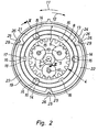
- the transmission includes a planetary gear 4 (it can several successive gear stages available ), which is a planetary gear with a central Sun gear 5, three distributed over the circumference arranged planetary gears 6 and an inner ring gear 7 having Ring gear 8 is formed.
- a planetary gear 4 (it can several successive gear stages available ), which is a planetary gear with a central Sun gear 5, three distributed over the circumference arranged planetary gears 6 and an inner ring gear 7 having Ring gear 8 is formed.
- the sun gear 5 is seated against rotation the motor shaft 9 or another from the machine motor ago driven shaft and meshes with those around the sun gear 5 around arranged planetary gears 6, located on the radially outside to roll arranged inner ring gear 7 of the ring gear 8.
- the Planetenradachsen 10 are components of the otherwise not shown web of the planetary gear, on the the subsequent gear stage or the drive shaft 2 driven becomes.
- the ring gear 8 is a safety device assigned.
- This safety device has a arranged fixed to the machine, the ring gear 8 enclosing bearing ring 13 on, arranged distributed over the circumference, in includes radial bearing through recesses 14, each one detent ball 15 movable in the radial direction take up.
- the wall thickness of the bearing ring 13 is smaller as the diameter of the detent ball 15.
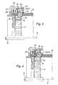
- the locking balls 15 are during normal operation below the turn-off torque with the ring gear 8 in latching engagement, so that the ring gear 8 is held against rotation ( Figures 2, 3 and 9).
- Verrastungseingriff are on the outer circumference of the ring gear 8 via the circumference distributed recesses 16 arranged. there Each detent ball 15 is associated with such a recess 16.
- the ring gear 8 six bearing recesses 16 on. In contrast, only three detent balls 15 are present so that only three locking recesses 16 with a detent ball 15 are occupied.
- the locking between the locking balls 15 and the recesses 16 is formed so that the ring gear 8 after outwardly directed force on the locking balls 15 exerts.
- the locking balls 15 are by means of a spring force to the ring gear. 8 loaded so that when the machine and during normal operation under the spring force on the ring gear 8 facing inside of the bearing ring 13 from the bearing recesses Protrude 14 and engage in the recesses 16.
- the spring force does not apply directly but over a support ring 19 to the locking balls 15 at.
- the support ring 19 encloses the bearing ring 13 and is movable in the axial direction arranged. In this case, the support ring 19 in axial Direction by the spring force applied.
- the support ring 19 also has a the locking balls 15 facing inclined surface arrangement 20, with the support ring 19 on the bearing balls 15 is present.
- the force with which the support ring 19 on the locking balls 15th acts and thus determines the turn-off torque depends not only on the spring force but also on the spring Cross-section ( Figures 3 to 10) seen slope of the inclined surface arrangement from.
- the hand tool according to the invention is the turn-off torque adjustable.
- the support ring 19 rotatably arranged on the hand tool 1 from the outside.
- the oblique surface arrangement of the above Scope distributed, each associated with a detent ball 15 and circumferentially extending inclined surface areas 21, 22, 23 are formed, within which in the circumferential direction the oblique surface slope seen in cross-section changed.
- the support ring 19 at three within the same Bevel area 21 at a distance in the circumferential direction show each other arranged locations.
- the three bevel areas 21, 22, 23 are the same.
- the support ring 19 rotatably, but in the axial direction movable with a him surrounding adjusting ring 24 connected to the outside is arranged accessible to the machine tool ago, as is apparent from Figure 1.
- the adjusting ring 24th rotatable and fixed in the axial direction on the machine housing stored.
- the non-rotatable and axially displaceable Connection of the support ring 19 and the adjusting ring 24th with each other can be made by, for example, that distributed outside on the support ring 19 over the circumference, axially directed guide grooves 25 and the adjusting ring 24 in the Guide grooves 25 engaging guide ribs 26 arranged be.
- the engineerssnuten inside the adjusting ring and the guide ribs on the support ring provided.
- the spring force, the support ring 19 against the locking balls 15th is held by one in the embodiment of several distributed over the circumference arranged coil springs 27 formed Spring assembly generated in the axial direction on the one hand on the adjusting ring 24 and on the other hand on the support ring 19 supported.
- the adjusting ring 24 has a radial inwardly directed ring section 28, at which the Support coil springs 27.
- the support ring should 19 as fast as possible in the axial direction, that over the locking balls 15 enough space for their exit is created from the recesses 16.
- the path of movement However, the support ring 19 is of the reference to the axial direction measured slope of the inclined surface arrangement 20 dependent. The smaller this slope is, the longer is the path of movement of the support ring 19. This corresponds a smaller slope a larger turn-off torque. Therefore, one designed for larger turn-off torques Safety device, you can see no further action slower than one for smaller turn-off torques designed safety device.
- the planetary gear three planet gears on. It is understood that too a different number of planetary gears could be present.
Landscapes
- Engineering & Computer Science (AREA)
- Mechanical Engineering (AREA)
- Transmission Devices (AREA)
- Retarders (AREA)
- Rolling Contact Bearings (AREA)
Abstract
Description
- Figur 1
- eine Handwerkzeugmaschine in Gestalt eines Schraubers in schematischer Seitenansicht,
- Figur 2
- eine Umlaufgetriebestufe des Schraubers nach Figur 1 mit der zugehörigen Sicherungseinrichtung in gesonderter Darstellung in axialer Richtung gemäß Pfeil II in Figur 1 gesehen,
- Figur 3
- die Anordnung nach Figur 2 im zur Zeichenebene der Figur 1 parallelen Halbschnitt gemäß der Schnittlinie III-III in Figur 2, wobei die innerhalb des Hohlrades angeordnete Getrieberadanordnung der Übersichtlichkeit wegen weggelassen ist und die Rastkugeln am Hohlrad eingerastet sind,
- Figur 4
- die Anordnung nach Figur 3, wobei das auf das Hohlrad einwirkende Drehmoment das Abschalt-Drehmoment erreicht hat, so dass die Rastkugeln aus den Rastausnehmungen des Hohlrads ausgetreten sind,
- Figur 5
- den Stützring der Sicherungseinrichtung nach den Figuren 2 und 4 in gesonderter Darstellung im den Figuren 3 und 4 entsprechenden Schnitt,
- Figuren 6, 7 und 8
- die Stützringwandung in Umfangsrichtung mit Abstand zueinander angeordneten Schnitten, wobei die Schnittebene der Figur 6 der Schnittebene der Figur 5 entspricht und die Schnitte gemäß den Figuren 7 und 8 etwa bei den Schnittlinien gemäß den Pfeilen VII-VII und VIII-VIII gelegt sind,
- Figur 9
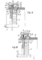
- eine der Figur 3 entsprechende Darstellung einer variierten Sicherungseinrichtung, bei der der Stützring anschließend an die Schrägflächenbereiche jeweils einen Neigungsbereich größerer Steigung aufweist und
- Figur 10
- die gleiche Variante in der Figur 4 entsprechender Darstellung.
Claims (6)
- Handwerkzeugmaschine, beispielsweise Schrauber, mit einem Mäschinenmotor und einer über ein Getriebe vom Maschinenmotor her zu einer Rotationsbewegung antreibbaren, mit einem Werkzeug verbindbaren Antriebswelle, wobei das Getriebe mindestens eine Umlaufgetriebestufe mit einer sich beim Betrieb am Innenzahnkranz eines Hohlrades abwälzenden Getrieberadanordnung enthält und wobei dem Hohlrad eine Sicherungseinrichtung zugeordnet ist, die durch Federkraft zum Hohlrad hin belastete, bewegbar gelagerte Rastkugeln aufweist, die beim Auftreten von mit Bezug auf ein Abschalt-Drehmoment kleineren Drehmomenten am Hohlrad mit dem Hohlrad in Verrastungseingriff stehen und dieses drehfest halten und beim Erreichen des Abschalt-Drehmoments vom Hohlrad entgegen der Federkraft aus ihrer Eingriffstellung verdrängt werden, so dass das Hohlrad an den Rastkugeln vorbeiratschen kann, dadurch gekennzeichnet, dass das Hohlrad (8) von einem maschinenfest angeordneten Lagerring (13) umschlossen ist, der über den Umfang verteilt angeordnete, in radialer Richtung durchgehende Lagerausnehmungen (14) zur Aufnahme jeweils einer Rastkugel (15) aufweist, wobei die Wandstärke des Lagerrings (13) kleiner als der Durchmesser der Rastkugeln (15) ist, dass am Außenumfang des Hohlrades (8) den Rastkugeln (15) zugeorndete Rastausnehmungen (16) angeordnet sind, dass der Lagerring (13) von einem in axialer Richtung bewegbaren Stützring (19) umschlossen ist, der durch die Federkraft in axialer Richtung belastet und über eine Schrägflächenanordnung (20) gegen die aus den Rastausnehmungen (16) vorstehenden und andererseit am Hohlrad (8) anliegenden Rastkugeln (15) gehalten wird, dass der Stützring (19) von außen her verdrehbar an der Handwerkzeugmaschine angeordnet ist und dass die Schrägflächenanordnung (20) von über den Umfang verteilten, jeweils einer Rastkugel (15) zugeordneten und sich in Umfangsrichtung erstreckenden Schrägflächenbereichen (21, 22, 23) gebildet wird, innerhalb von denen sich in Umfangsrichtung die im Querschnitt gesehene Schrägflächensteigung verändert, so dass je nach der Drehlage des Stützrings (19) die Schrägflächenbereiche (21, 22, 23) mit einer anderen Steigung an den Rastkugeln (15) anliegen.
- Handwerkzeugmaschine nach Anspruch 1, dadurch gekennzeichnet, dass sich in axialer Richtung an die Schrägflächenbereiche (21, 22, 23) jeweils ein sich in Umfangsrichtung dem betreffenden Schrägflächenbereich entlang erstreckender Neigungsflächenbereich (30) anschließt, wobei die Neigungsflächenbereiche (30) eine mit Bezug auf die axiale Richtung größere Steigung als die Schrägflächenbereiche (21, 22, 23) aufweisen.
- Handwerkzeugmaschine nach Anspruch 1 oder 2, dadurch gekennzeichnet, dass der Stützring (19) in axialer Richtung anschließend an die Schrägflächenbereiche (21, 22, 23) bzw. an die Neigungsflächenbereiche (30) eine in axialer Richtung vorstehende Ringpartie (32) als Ausfallsicherung für die Rastkugeln (15) aufweist.
- Handwerkzeugmaschine nach einem der Ansprüche 1 bis 3, dadurch gekennzeichnet, dass am Innenumfang des Stützrings (19) in Umfangsrichtung zwischen den Schrägflächenbereichen (21, 22, 23) jeweils eine zum Lagerring (13) hin vorstehende Rückhaltepartie (29) angeordnet ist, so dass bei über die Rastkugeln (15) gedrehten Rückhaltepartien (29) die Rastkugeln (15) unabhängig vom am Hohlrad (8) auftretenden Drehmoment in den Rastausnehmungen (16) des Hohlrades (8) gehalten werden.
- Handwerkzeugmaschine nach einem der Ansprüche 1 bis 4, dadurch gekennzeichnet, dass der Stützring (19) drehfest, dabei jedoch axial beweglich mit einem ihn umschließenden, von außen her zugänglichen, verdrehbar und axial feststehend gelagerten Verstellring (24) verbunden ist, wobei sich eine die Federkraft erzeugende Federanordnung (27) in axialer Richtung einerseits am Verstellring (24) und andererseits am Stützring (19) abstützt.
- Handwerkzeugmaschine nach Anspruch 5, dadurch gekennzeichnet, dass außen am Stützring (19) oder innen am Verstellring über den Umfang verteilte, axial gerichtete Führungsnuten (25) und am Verstellring (24) oder am Stützring in die Führungsnuten (25) eingreifende Führungsrippen (26) angeordnet sind.
Applications Claiming Priority (2)
| Application Number | Priority Date | Filing Date | Title |
|---|---|---|---|
| DE2002139483 DE10239483B3 (de) | 2002-08-21 | 2002-08-21 | Handwerkzeugmaschine, beispielsweise Schrauber |
| DE10239483 | 2002-08-21 |
Publications (3)
| Publication Number | Publication Date |
|---|---|
| EP1391269A2 true EP1391269A2 (de) | 2004-02-25 |
| EP1391269A3 EP1391269A3 (de) | 2006-05-10 |
| EP1391269B1 EP1391269B1 (de) | 2007-03-14 |
Family
ID=30775569
Family Applications (1)
| Application Number | Title | Priority Date | Filing Date |
|---|---|---|---|
| EP20030013591 Expired - Lifetime EP1391269B1 (de) | 2002-08-21 | 2003-06-14 | Handwerkzeugmaschine, beispielsweise Schrauber |
Country Status (2)
| Country | Link |
|---|---|
| EP (1) | EP1391269B1 (de) |
| DE (2) | DE10239483B3 (de) |
Cited By (6)
| Publication number | Priority date | Publication date | Assignee | Title |
|---|---|---|---|---|
| EP1787757A1 (de) | 2005-11-18 | 2007-05-23 | Metabowerke GmbH | Elektromotorisch angetriebenes Schraub-oder Bohrwerkzeuggerät mit Planetengetriebe |
| CN101396811B (zh) * | 2007-09-28 | 2012-04-25 | 苏州宝时得电动工具有限公司 | 动力工具 |
| CN102748443A (zh) * | 2012-06-01 | 2012-10-24 | 李飞宇 | 行星齿轮过载保护装置 |
| CN113001478A (zh) * | 2019-12-19 | 2021-06-22 | 罗伯特·博世有限公司 | 用于手持式工具机的手持式工具机设备及钻锤 |
| US12589477B2 (en) | 2023-11-30 | 2026-03-31 | Stanley Black & Decker Inc. | Multi-headed power tool and fastening system for same and systems for fastening heads thereon |
| US12594657B2 (en) | 2023-11-30 | 2026-04-07 | Stanley Black & Decker, Inc. | Multi-headed power tool and systems for fastening heads thereon |
Family Cites Families (7)
| Publication number | Priority date | Publication date | Assignee | Title |
|---|---|---|---|---|
| DE1860599U (de) * | 1962-08-10 | 1962-10-18 | Metabowerke Kg | Elektrisch betriebenes schraubwerkzeug. |
| DE2409815A1 (de) * | 1974-03-01 | 1975-09-11 | Bosch Gmbh Robert | Kraftschrauber mit abschalteinrichtung |
| US4448098A (en) * | 1982-03-10 | 1984-05-15 | Katsuyuki Totsu | Electrically driven screw-driver |
| DE3636301A1 (de) * | 1986-10-24 | 1988-04-28 | Steinel Gmbh & Co Kg | Handwerkszeug |
| NL9101335A (nl) * | 1991-08-02 | 1993-03-01 | Emerson Electric Co | Transmissie voor elektrisch aangedreven gereedschap. |
| US5897454A (en) * | 1996-01-31 | 1999-04-27 | Black & Decker Inc. | Automatic variable transmission for power tool |
| DE19902187A1 (de) * | 1998-03-04 | 1999-09-16 | Scintilla Ag | Gangumschaltbares Planetengetriebe |
-
2002
- 2002-08-21 DE DE2002139483 patent/DE10239483B3/de not_active Expired - Fee Related
-
2003
- 2003-06-14 EP EP20030013591 patent/EP1391269B1/de not_active Expired - Lifetime
- 2003-06-14 DE DE50306785T patent/DE50306785D1/de not_active Expired - Lifetime
Cited By (7)
| Publication number | Priority date | Publication date | Assignee | Title |
|---|---|---|---|---|
| EP1787757A1 (de) | 2005-11-18 | 2007-05-23 | Metabowerke GmbH | Elektromotorisch angetriebenes Schraub-oder Bohrwerkzeuggerät mit Planetengetriebe |
| US7537540B2 (en) | 2005-11-18 | 2009-05-26 | Metabowerke Gmbh | Electric motor driven screw driving or drilling tool device with planetary gear |
| CN101396811B (zh) * | 2007-09-28 | 2012-04-25 | 苏州宝时得电动工具有限公司 | 动力工具 |
| CN102748443A (zh) * | 2012-06-01 | 2012-10-24 | 李飞宇 | 行星齿轮过载保护装置 |
| CN113001478A (zh) * | 2019-12-19 | 2021-06-22 | 罗伯特·博世有限公司 | 用于手持式工具机的手持式工具机设备及钻锤 |
| US12589477B2 (en) | 2023-11-30 | 2026-03-31 | Stanley Black & Decker Inc. | Multi-headed power tool and fastening system for same and systems for fastening heads thereon |
| US12594657B2 (en) | 2023-11-30 | 2026-04-07 | Stanley Black & Decker, Inc. | Multi-headed power tool and systems for fastening heads thereon |
Also Published As
| Publication number | Publication date |
|---|---|
| DE10239483B3 (de) | 2004-03-04 |
| EP1391269B1 (de) | 2007-03-14 |
| EP1391269A3 (de) | 2006-05-10 |
| DE50306785D1 (de) | 2007-04-26 |
Similar Documents
| Publication | Publication Date | Title |
|---|---|---|
| DE69400262T2 (de) | Motorgetriebenes Gerät und Mechanismus dafür | |
| DE69508518T2 (de) | Umkehrbarer angetriebener Schraubenschlüssel | |
| EP2358502B1 (de) | Schaltbares planetengetriebe in einer handwerkzeugmaschine | |
| EP2837466B1 (de) | Spanneinheit, insbesondere zur Verwendung in einem Bearbeitungszentrum bzw. einem Dreh- bzw. Fräszentrum | |
| EP1787757B1 (de) | Elektromotorisch angetriebenes Schraub-oder Bohrwerkzeuggerät mit Planetengetriebe | |
| WO2012110321A1 (de) | Handwerkzeugmaschine mit einem untersetzungsgetriebe | |
| DE102009027223A1 (de) | Handgeführtes Elektrowerkzeug | |
| EP2445675B1 (de) | Handgeführtes elektrowerkzeug | |
| EP2140978B1 (de) | Schlagschrauber | |
| EP1979134B1 (de) | Getriebe, insbesondere für elektrohandwerkzeugmaschinen | |
| DE102012018528A1 (de) | Spannsystem mit einem Rotationsantrieb | |
| EP3279492B1 (de) | Spanneinrichtung für werkzeuge | |
| DE102013113868A1 (de) | Bohrvorrichtung und Bohrfutter | |
| DE2835303A1 (de) | Schalteinrichtung fuer zahnraederwechselgetriebe von werkzeugmaschinen | |
| EP2228157A1 (de) | Elektromotorisch angetriebenes Schraub- oder Bohrwerkzeug | |
| DE102014104367A1 (de) | Bohrvorrichtung und Rutschkupplung für eine Bohrvorrichtung | |
| EP1391269B1 (de) | Handwerkzeugmaschine, beispielsweise Schrauber | |
| DE2726080C2 (de) | Anordnung zum Verschieben eines Wälzlagers in beiden axialen Richtungen | |
| EP2095909A1 (de) | Planetengetriebe für ein Elektrohandwerkzeuggerät sowie Elektrohandwerkzeuggerät | |
| WO2012041428A1 (de) | Getriebevorrichtung | |
| EP0808695A2 (de) | Schlagbohrmachine | |
| WO2021004578A1 (de) | Parksperrenvorrichtung für eine elektrische antriebsachse und elektrische antriebsachse mit einer parksperrenvorrichtung | |
| EP2180979B1 (de) | Elektrohandwerkzeuggerät | |
| WO2015083040A2 (de) | Planeten-schraubenrad-getriebe | |
| EP0995551A2 (de) | Handführbare Werkzeugmaschine, insbesondere Schrauber oder Bohrschrauber |
Legal Events
| Date | Code | Title | Description |
|---|---|---|---|
| PUAI | Public reference made under article 153(3) epc to a published international application that has entered the european phase |
Free format text: ORIGINAL CODE: 0009012 |
|
| AK | Designated contracting states |
Kind code of ref document: A2 Designated state(s): AT BE BG CH CY CZ DE DK EE ES FI FR GB GR HU IE IT LI LU MC NL PT RO SE SI SK TR |
|
| AX | Request for extension of the european patent |
Extension state: AL LT LV MK |
|
| PUAL | Search report despatched |
Free format text: ORIGINAL CODE: 0009013 |
|
| AK | Designated contracting states |
Kind code of ref document: A3 Designated state(s): AT BE BG CH CY CZ DE DK EE ES FI FR GB GR HU IE IT LI LU MC NL PT RO SE SI SK TR |
|
| AX | Request for extension of the european patent |
Extension state: AL LT LV MK |
|
| 17P | Request for examination filed |
Effective date: 20060413 |
|
| GRAP | Despatch of communication of intention to grant a patent |
Free format text: ORIGINAL CODE: EPIDOSNIGR1 |
|
| GRAS | Grant fee paid |
Free format text: ORIGINAL CODE: EPIDOSNIGR3 |
|
| AKX | Designation fees paid |
Designated state(s): CH DE FR GB LI |
|
| GRAA | (expected) grant |
Free format text: ORIGINAL CODE: 0009210 |
|
| AK | Designated contracting states |
Kind code of ref document: B1 Designated state(s): CH DE FR GB LI |
|
| REG | Reference to a national code |
Ref country code: GB Ref legal event code: FG4D Free format text: NOT ENGLISH |
|
| GBT | Gb: translation of ep patent filed (gb section 77(6)(a)/1977) |
Effective date: 20070314 |
|
| REG | Reference to a national code |
Ref country code: CH Ref legal event code: NV Representative=s name: TROESCH SCHEIDEGGER WERNER AG Ref country code: CH Ref legal event code: EP |
|
| REF | Corresponds to: |
Ref document number: 50306785 Country of ref document: DE Date of ref document: 20070426 Kind code of ref document: P |
|
| ET | Fr: translation filed | ||
| PLBE | No opposition filed within time limit |
Free format text: ORIGINAL CODE: 0009261 |
|
| STAA | Information on the status of an ep patent application or granted ep patent |
Free format text: STATUS: NO OPPOSITION FILED WITHIN TIME LIMIT |
|
| 26N | No opposition filed |
Effective date: 20071217 |
|
| REG | Reference to a national code |
Ref country code: DE Ref legal event code: R082 Ref document number: 50306785 Country of ref document: DE Representative=s name: PATENTANWAELTE MAGENBAUER & KOLLEGEN, DE |
|
| REG | Reference to a national code |
Ref country code: DE Ref legal event code: R081 Ref document number: 50306785 Country of ref document: DE Owner name: FESTOOL GROUP GMBH & CO. KG, DE Free format text: FORMER OWNER: FESTOOL GMBH, 73240 WENDLINGEN, DE Effective date: 20121119 Ref country code: DE Ref legal event code: R082 Ref document number: 50306785 Country of ref document: DE Representative=s name: PATENTANWAELTE MAGENBAUER & KOLLEGEN, DE Effective date: 20121119 Ref country code: DE Ref legal event code: R081 Ref document number: 50306785 Country of ref document: DE Owner name: FESTOOL GMBH, DE Free format text: FORMER OWNER: FESTOOL GMBH, 73240 WENDLINGEN, DE Effective date: 20121119 Ref country code: DE Ref legal event code: R082 Ref document number: 50306785 Country of ref document: DE Representative=s name: PATENTANWAELTE MAGENBAUER & KOLLEGEN PARTNERSC, DE Effective date: 20121119 |
|
| PGFP | Annual fee paid to national office [announced via postgrant information from national office to epo] |
Ref country code: CH Payment date: 20140627 Year of fee payment: 12 |
|
| REG | Reference to a national code |
Ref country code: DE Ref legal event code: R082 Ref document number: 50306785 Country of ref document: DE Representative=s name: PATENTANWAELTE MAGENBAUER & KOLLEGEN PARTNERSC, DE |
|
| REG | Reference to a national code |
Ref country code: DE Ref legal event code: R082 Ref document number: 50306785 Country of ref document: DE Representative=s name: PATENTANWAELTE MAGENBAUER & KOLLEGEN PARTNERSC, DE Effective date: 20141104 Ref country code: DE Ref legal event code: R081 Ref document number: 50306785 Country of ref document: DE Owner name: FESTOOL GMBH, DE Free format text: FORMER OWNER: FESTOOL GROUP GMBH & CO. KG, 73240 WENDLINGEN, DE Effective date: 20141104 |
|
| REG | Reference to a national code |
Ref country code: CH Ref legal event code: PL |
|
| PG25 | Lapsed in a contracting state [announced via postgrant information from national office to epo] |
Ref country code: LI Free format text: LAPSE BECAUSE OF NON-PAYMENT OF DUE FEES Effective date: 20150630 Ref country code: CH Free format text: LAPSE BECAUSE OF NON-PAYMENT OF DUE FEES Effective date: 20150630 |
|
| REG | Reference to a national code |
Ref country code: FR Ref legal event code: PLFP Year of fee payment: 14 |
|
| REG | Reference to a national code |
Ref country code: FR Ref legal event code: PLFP Year of fee payment: 15 |
|
| REG | Reference to a national code |
Ref country code: FR Ref legal event code: PLFP Year of fee payment: 16 |
|
| PGFP | Annual fee paid to national office [announced via postgrant information from national office to epo] |
Ref country code: GB Payment date: 20220623 Year of fee payment: 20 Ref country code: DE Payment date: 20220511 Year of fee payment: 20 |
|
| PGFP | Annual fee paid to national office [announced via postgrant information from national office to epo] |
Ref country code: FR Payment date: 20220622 Year of fee payment: 20 |
|
| REG | Reference to a national code |
Ref country code: DE Ref legal event code: R071 Ref document number: 50306785 Country of ref document: DE |
|
| P01 | Opt-out of the competence of the unified patent court (upc) registered |
Effective date: 20230519 |
|
| REG | Reference to a national code |
Ref country code: GB Ref legal event code: PE20 Expiry date: 20230613 |
|
| PG25 | Lapsed in a contracting state [announced via postgrant information from national office to epo] |
Ref country code: GB Free format text: LAPSE BECAUSE OF EXPIRATION OF PROTECTION Effective date: 20230613 |