EP1389896B1 - Verfahren zur periodischen verlängerung einer elektrode für einen elektrischen bogenofen und elektrode für einen elektrischen bogenofen - Google Patents
Verfahren zur periodischen verlängerung einer elektrode für einen elektrischen bogenofen und elektrode für einen elektrischen bogenofen Download PDFInfo
- Publication number
- EP1389896B1 EP1389896B1 EP02757758A EP02757758A EP1389896B1 EP 1389896 B1 EP1389896 B1 EP 1389896B1 EP 02757758 A EP02757758 A EP 02757758A EP 02757758 A EP02757758 A EP 02757758A EP 1389896 B1 EP1389896 B1 EP 1389896B1
- Authority
- EP
- European Patent Office
- Prior art keywords
- electrode
- nipple
- rod
- electric arc
- arc furnace
- Prior art date
- Legal status (The legal status is an assumption and is not a legal conclusion. Google has not performed a legal analysis and makes no representation as to the accuracy of the status listed.)
- Expired - Lifetime
Links
- 238000000034 method Methods 0.000 title claims abstract description 76
- 238000010891 electric arc Methods 0.000 title claims abstract description 39
- 210000002445 nipple Anatomy 0.000 claims abstract description 100
- 229910052751 metal Inorganic materials 0.000 claims abstract description 38
- 239000002184 metal Substances 0.000 claims abstract description 38
- 230000000737 periodic effect Effects 0.000 claims abstract description 19
- 239000004411 aluminium Substances 0.000 claims abstract description 18
- 229910052782 aluminium Inorganic materials 0.000 claims abstract description 18
- XAGFODPZIPBFFR-UHFFFAOYSA-N aluminium Chemical compound [Al] XAGFODPZIPBFFR-UHFFFAOYSA-N 0.000 claims abstract description 18
- RYGMFSIKBFXOCR-UHFFFAOYSA-N Copper Chemical compound [Cu] RYGMFSIKBFXOCR-UHFFFAOYSA-N 0.000 claims abstract description 17
- 229910052802 copper Inorganic materials 0.000 claims abstract description 17
- 239000010949 copper Substances 0.000 claims abstract description 17
- 239000000463 material Substances 0.000 claims description 21
- 238000002844 melting Methods 0.000 claims description 21
- 230000008018 melting Effects 0.000 claims description 21
- 239000000126 substance Substances 0.000 claims description 13
- 239000008187 granular material Substances 0.000 claims description 8
- 238000012856 packing Methods 0.000 claims description 7
- 229910001338 liquidmetal Inorganic materials 0.000 abstract description 11
- 239000000203 mixture Substances 0.000 abstract description 4
- 238000002360 preparation method Methods 0.000 description 16
- OKTJSMMVPCPJKN-UHFFFAOYSA-N Carbon Chemical compound [C] OKTJSMMVPCPJKN-UHFFFAOYSA-N 0.000 description 14
- 229910000831 Steel Inorganic materials 0.000 description 12
- 239000010959 steel Substances 0.000 description 12
- 229910002804 graphite Inorganic materials 0.000 description 11
- 239000010439 graphite Substances 0.000 description 11
- 230000008569 process Effects 0.000 description 8
- 238000005304 joining Methods 0.000 description 5
- 230000008859 change Effects 0.000 description 4
- 230000007423 decrease Effects 0.000 description 4
- 230000000694 effects Effects 0.000 description 4
- 239000007788 liquid Substances 0.000 description 4
- 238000004519 manufacturing process Methods 0.000 description 4
- 230000003247 decreasing effect Effects 0.000 description 3
- 238000010438 heat treatment Methods 0.000 description 3
- 150000002739 metals Chemical class 0.000 description 3
- 230000000704 physical effect Effects 0.000 description 3
- 230000007704 transition Effects 0.000 description 3
- 238000009835 boiling Methods 0.000 description 2
- 229910052799 carbon Inorganic materials 0.000 description 2
- 238000002485 combustion reaction Methods 0.000 description 2
- 230000006835 compression Effects 0.000 description 2
- 238000007906 compression Methods 0.000 description 2
- 230000006866 deterioration Effects 0.000 description 2
- 239000004744 fabric Substances 0.000 description 2
- 239000011347 resin Substances 0.000 description 2
- 229920005989 resin Polymers 0.000 description 2
- 239000007787 solid Substances 0.000 description 2
- 208000031636 Body Temperature Changes Diseases 0.000 description 1
- 239000000571 coke Substances 0.000 description 1
- 230000006378 damage Effects 0.000 description 1
- 230000001419 dependent effect Effects 0.000 description 1
- 238000009826 distribution Methods 0.000 description 1
- 238000009851 ferrous metallurgy Methods 0.000 description 1
- 239000008246 gaseous mixture Substances 0.000 description 1
- 239000000155 melt Substances 0.000 description 1
- 238000005457 optimization Methods 0.000 description 1
- 239000002344 surface layer Substances 0.000 description 1
Images
Classifications
-
- H—ELECTRICITY
- H05—ELECTRIC TECHNIQUES NOT OTHERWISE PROVIDED FOR
- H05B—ELECTRIC HEATING; ELECTRIC LIGHT SOURCES NOT OTHERWISE PROVIDED FOR; CIRCUIT ARRANGEMENTS FOR ELECTRIC LIGHT SOURCES, IN GENERAL
- H05B7/00—Heating by electric discharge
- H05B7/02—Details
- H05B7/14—Arrangements or methods for connecting successive electrode sections
-
- Y—GENERAL TAGGING OF NEW TECHNOLOGICAL DEVELOPMENTS; GENERAL TAGGING OF CROSS-SECTIONAL TECHNOLOGIES SPANNING OVER SEVERAL SECTIONS OF THE IPC; TECHNICAL SUBJECTS COVERED BY FORMER USPC CROSS-REFERENCE ART COLLECTIONS [XRACs] AND DIGESTS
- Y02—TECHNOLOGIES OR APPLICATIONS FOR MITIGATION OR ADAPTATION AGAINST CLIMATE CHANGE
- Y02P—CLIMATE CHANGE MITIGATION TECHNOLOGIES IN THE PRODUCTION OR PROCESSING OF GOODS
- Y02P10/00—Technologies related to metal processing
- Y02P10/25—Process efficiency
Definitions
- the disclosed invention relates to manufacturing of steel in electric arc furnaces in ferrous metallurgy.
- the energy necessary for metal melting is supplied by the electrode column formed as a set of electrodes joined by threaded nipples.
- the electrode column With wear of the electrode, the electrode column is elongated periodically by means of screwing together a new electrode and a nipple, prepared in advance with the active electrode of the said column.
- the specific character of the current flow through the electrode joint (connection) determines, in its turn, the heat released in this part of the electrode column and, consequently, the heating-up of the electrode in the process of its operation
- High heating-up temperatures of the electrode in the electric arc furnace considerably enhance its wear and increase the use of costly electrodes per ton of steel made
- the method of preliminary preparation of the electrode plays a significant role for the practical realization of the method of periodic elongation of the electric arc furnace electrode.
- the known method proposes to solve the problem of reducing the prestressing force of the electrode connection that decreases the working capacity of the electrodes
- the main drawback of the known method consists in leaving the traditional way the current flows through the joint "electrodes - nipple" unchanged.
- the known method does not solve the problem of easing the current flow at the joint "electrodes - nipple", which leads to increased heat release in this part of the electrode arc due to additional resistance in the contacts "electrode-nipple-electrode”. High heating-up temperatures of electrodes enhance their wear.
- Document GB 18733 discloses a method for periodic elongation of an electrode according to the preamble of claim 1 as well as an electrode column for an electric furnace according to the preamble of independent claim 5. Similar electrodes are also well known from documents FR-A-2 324 189 , GB-A-1 243 536 , US-A-4 725 161 and EP-A1-0 101 819 .
- the disadvantage of the known electrode is the lack of the technical solution for easing the electric current flow through the joints "electrodes-nipple" after its joining with the active electrode of the electric arc furnace.
- the said known electrode is the closest to the disclosed electrode due to which it was adopted as a prototype.
- the disadvantage of the known electrode is the lack of the technical solution in its design for easing the electric current flow through the joints "electrodes-nipple" after its joining with the active electrode of the electric arc furnace.
- functioning of the electrode in the electric arc furnace results in higher resistance to the electric current flow in the joint and release of additional energy that leads to greater heating-up of the junction and the nipple.
- the latter makes the working conditions of the electrode worse and decreases its performance.
- the disclosed electrode is free of the mentioned drawbacks. Its design provides for a technical solution that allows the resistance to the electric current flow in the junction "electrodes-nipple" to be decreased significantly after joining the electrode to the electric arc column. This allows decreasing the general heating-up temperature level of the electrodes and the nipple in their junction and, based on this, reducing the factors of increased electrode wear.
- the electrode having on both its sides threaded sockets ending up with additional threadless sections, according to the invention is equipped with additional threadless cavities - at the bottom of the threaded socket, in the middle, at least on one side of the electrode and at most on its both sides, the depth and the diameter of the said cavity on one of the sides of the electrode having larger values and the cavity being connected to the external surface of the electrode by means of holes. Meanwhile the holes connecting the additional cavity with the external surface of the electrode are inclined, performed at an angle to the other side of the electrode.
- the advantages of the known method include a noticeable simplification of the procedure for periodic elongation of the electrode under the industrial conditions of the electric arc furnace operation.
- the known method has a significant drawback consisting in the fact that the process of preliminary preparation of the electrode in this method includes no methods for considerably decreasing the resistance to the electric current flow in the junction "electrodes-nipple" during the work of the electrode in the electric arc furnace.
- the said drawback prevents reducing the temperatures up to which the electrode is heating up in this junction, which, in its case, diminishes its performance.
- the disclosed method for preliminary preparation of the electrode uses the mentioned advantages of the known method, but is free of its drawbacks. It provides for realizing the techniques that allow, while operating the electrode in the electric arc furnace, an essential decrease in the electrode heating-up temperatures at the junction "electrodes-nipple" and an increase in the performance of the electrode on this base.
- the said metal rod is compressed to the nipple by means of metal swarf and (or) granules made of the same material as the rod Also the said metal rod is compressed to the nipple by means of packing substance that burns out under the working temperature of the electrode in the electric arc furnace.
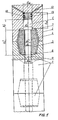
- Fig 1 shows the electrode after the accomplishment of the procedure of periodic elongation of the electrode column.
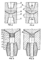
- Fig.2 and 3 show versions of the electrode for the procedure of periodic elongation of the electrode column.
- Fig. 4 and 5 show realization versions for the method of preliminary preparation of the electrode for the accomplishment of the method for periodic elongation of the electrode column.
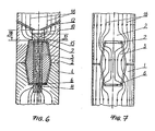
- Fig. 6 shows the main features of the electric current flow through the joint "electrodes-nipple" in the disclosed method for elongating the electrode.
- Fig.7 shows the main features of the electric current flow through the joint "electrodes-nipple" in the known method for elongating the electrode.
- the electrode column of the electric arc furnace consists of several acting electrodes ( fig. 1 ) joined by means of a biconic threaded nipple. With the help of new electrode 2 and nipple 3 the electrode column is periodically elongated. Nipple 3 has longitudinal through hole 4 into which metal rod 5, made of the metal with much lower specific electric resistance as compared with the material of the electrode and the nipple (aluminium, copper), is inserted. Between nipple 3 and acting electrode 1 there exists cavity 6 that may remain free or partially filled with substance contributing to better junction of the nipple and the electrode. The same cavity 7 exists between new electrode 2 and the nipple. It may also be free or, as with cavity 6, partially filled with analogous substance.
- Electrode 2 ( fig. 2 and 3 ) is asymmetric in length: it is equipped with two identical threaded sockets 8 and 9 and additional different threadless cavities 10 and 11. Electrode 2 may include only cavity 10 on one of its sides ( fig. 2 ), or two cavities 10 and 11 ( fig. 3 ) on both sides of the said electrode. Furthermore, cavity 10 is of bigger diameter ( d 10 > d 11 at fig. 3 ) and greater depth ( h 10 > h 11 at fig. 3 ) as compared with cavity 11. And the cavity of bigger diameter and depth, i.e. cavity 10, in its upper part is connected to the external surface of the electrode by means of holes 12.
- Preliminary prepared electrode 2 and nipple 3 have in longitudinal through hole 4 two-stage metal rod 5 one stage of which is of greater diameter d 5 * in comparison with the other d 5 * * , i.e. d 5 * > d 5 * * .
- diameter d 5 * * of rod 5 is smaller than diameter d 4 of nipple hole 3 by the amount of the rod metal linear expansion for the case of increasing temperature from ⁇ 20°C to the melting temperature of the rod.
- diameter d 5 * i.e. d 5 * ⁇ d 10 (in fig. 1 , 5 and 6 it is not shown to prevent cluttering figures) by the value of the said thermal expansion.
- Two-stage metal rod 5 with the stage of greater diameter d 5 * is installed in cavity 10 of electrode 2.
- the height of said rod stage h 5 * is smaller than the depth of cavity 10 of electrode 2, i.e. h 5 * ⁇ h 10 .
- the diameter of the metal rod stage d 5 * is greater than the diameter of through hole 4 in nipple 3, i.e. d 5 * > d 4 .
- spring 13 fig. 1 and 4
- packing substance 14 is deposited ( fig. 5 ), that burns out or melts under the working temperature of the electrode in the electric arc furnace.
- Metal rod 5 after melting under the electrode working temperature turns into liquid metal 15 ( fig. 6 ) which completely fills up the majority of the cavities in the joint "electrodes-nipple": longitudinal through hole 4 in nipple 3, cavity 6 between nipple 3 and the bottom of the threaded socket of acting electrode 1, additional cavity 11 (in case it exists) in acting electrode 1, and cavity 7 between nipple 3 and the bottom of the threaded socket of new electrode 2 with partial filling of additional cavity 10 up to the level h M in new electrode 2 (i.e. h M ⁇ h 10 ).
- metal swarf and/or granules 14 also turn into liquid metal15 ( fig. 4 ), in case they are used.
- Dimensions of two-stage metal rod 5, spring 13, swarf and/or granules 14 provide for the mentioned filling up of cavities formed after screwing together electrodes 1 and 2 and nipple 3.
- the main flows of electric current 16 for the case of realizing the present invention pass through the joint "connected electrodes 1 and 2 - nipple 3", as shown in fig. 6 , and for the known method - as shown in fig. 7 .
- the method for periodic elongation of the electrode for the electric arc furnace is accomplished in the following way.
- electrode 2 ( fig. 2 and 3 ) of the known design (made of graphite or carbon), having on both sides identical threaded sockets 8 and 9, additional threadless cavities 10 and 11 d are executed along the electrode axle ( fig. 3 ). Meanwhile, if the next screwing together of acting electrode 1 with nipple 3 ( fig. 1 ) takes place without filling cavity 6 with substance for better junction of nipple 3 and electrode 1, it is possible not to make additional cavity 11 in the electrode ( fig. 2 ).
- Cavities 10 and 11 are executed in the center of the bottom of threaded sockets 8 and 9 so, that they have different diameters d 10 and d 11 as well as different depths h 10 and h 11 .
- Cavity 10 in its part nearer to the bottom or with an outlet to the bottom, by means of holes 12 (the number of which is usually not less than 2) is connected to the external surface. Holes 12 are performed inclined, at an angle to the other side of the electrode ( fig. 2 and 3 ).
- Preliminary preparation of electrode 2 ( fig. 2 and 3 ) is accomplished in the following way.
- Electrode 2 is screwed together with nipple 3 ( fig. 4 and 5 ) having longitudinal through hole 4 with diameter d 4 . Screwing together is carried out by the side of electrode 2 executed with additional cavity 10, i.e. nipple 3 is screwed into threaded socket 9.
- spring 13 and two-stage rod 5 are installed in cavity 10, rod 5 stage of greater diameter d 5 * being placed into cavity 10.
- Spring 13 is made of the same metal as the rod.
- Packing material 14 may be used in place of spring 13 in cavity 10 ( fig. 5 ). This material may be swarf, granules or a mixture of swarf and granules of the same material as rod 5.
- the packing material may be fabric, paper or other substance the combustion temperature of which is lower than the electrode working temperature during its work in the electric arc furnace (400...500 °C beyond the furnace area, and up to 2100...2500 °C in the working area of the furnace).
- Screwing together electrode 2 and nipple 3 provides for the existence of cavity 7.
- the current invention does not consider this known operation, as its implementation does not change the essence of the invention.
- the named operations of preliminary preparation of the electrode and the nipple are carried out at the electrode manufacturing plant and the consumer receives the new electrode in the form presented in fig. 4 and 5 .
- the cavity of threaded socket 8 with additional cavity 11 is cleaned on acting electrode 1 of the electrode column by means of compressed air.
- the realization of this method preserves the main operations of the elongation procedure for the electric arc furnace electrode.
- the use of the proposed method for electrode elongation, the electrode itself and the method of its preliminary preparation fundamentally changes the way the electric current flows through the joint "electrodes 1 and 2 - nipple 3" in comparison with the known method.
- the change is that under the disclosed method main flows of electric current 16 ( fig. 6 ) bypass the joint, while under the known method ( fig. 7 ) these flows have to pass through the junction "connected electrodes 1 and 2 - nipple 3" with significant electric resistance.
- the said picture of the known method is additionally worsened by the fact that with the increase in the temperature of the joint area, caused by its entrance into the working area of the furnace, the contact in the junctions "electrode 2 - electrode 1 - nipple 3" deteriorates.
- the said formulas determine for chosen diameters of rod stages d 5 * and d 5 * * their linear dimensions h 5 * and h 5 * * .
- an addition of the liquid metal volume due to the melting of spring 13 or metal swarf/granules 14 is also taken into consideration.
- T M ⁇ 2 ⁇ c 2 ⁇ T 2 ⁇ ⁇ M ⁇ M ⁇ c M ⁇ ⁇ 2 ⁇ D 2 4 d 2 4 ,
- Correspondence (3) is used while choosing diameter d 4 of the hole in nipple 3 for the known properties of the material of electrode 2 and nipple 3, as well as of the metal used for rod 5.
- One proceeds from T 2 values of electrode 2 and nipple 3 heating-up in the known method and the preferable temperatures of liquid metal heating-up T M in the disclosed method as a result of the equal strength current passage.
- the rod stage diameter d 5 * * is set.
- the diameter of cavity 11 is set 10...20 mm greater than diameter d 4 , in order to eliminate abutting of rod 5 against acting electrode 1 during the electrode column elongation procedure.
- the diameter of cavity 10 is set 30...40 mm greater than diameter d 4 , in order to provide sure compression of rod stage with diameter d 5 * to the nipple face.
- Diameter d 5 * is set on the basis of the above mentioned effects related to the linear thermal expansion of the rod and the nipple.
- the passage of the above mentioned current through the column would result in the heating of joints "electrode-nipple" within the furnace up to the temperature of T 2 ⁇ 2300 °C.
- the mentioned high value of temperature is, firstly, due to the necessity of using high amperage, secondly, due to high specific electric resistance of the electrode and the nipple materials and, thirdly, due to the design of the joint "electrode-nipple" and, consequently, due to the method of their elongation.
- the known design of the electrode and the electrode column elongation method includes the joint "new electrode - nipple - acting electrode" through which the electric current passes according to the scheme shown in figure 7 having significant resistance on its way in places where the connected elements are in contact. Furthermore, because of the intensive heating-up of the electrodes and the nipple, the junction density provided at the stage of preliminary preparation of the electrode and during the elongation procedure deteriorates. It results in a multi-fold increase in the electric resistance of the stated contacts of the electrodes and the nipple being joint, which is hard to forecast and uncontrolled. Let's assume that the resistance in the known elongation method at the temperature of 2300 °C increases three-fold. The release of heat at the mentioned contacts leads to enhanced heating-up within the electrode and growth of tangential stress in the surface layers of the electrode. The latter increases the probability of destroying electrode and enhances the use of electrodes per ton of the steel produced.
- Aluminium metal rod 5 is used.
- T M 1700 °C and given above physical properties of graphite and aluminium
- the volume of cavities 6 and 7 is set about the same and equal to 2500 cm 3 for each cavity.
- a new electrode fig. 2 and 3
- a nipple and a metal rod of aluminium are produced, get preliminary preparation ( fig. 4 and 5 ) and delivered in this state for elongation of the electrode for the electric arc furnace.
- the disclosed electrode ( fig. 2 or 3 ) is used.
- the properties of the electrode and the nipple are the same as in example 1.
- Copper rod 5 is inserted into the electrode during the process of preliminary assembling (preparation).
- nipple parameters are unified, and in the same way as in example 1 value d 4 is set equal to 240 mm.
- the realization of the disclosed method for periodic elongation of the electrode for the electric arc furnace, the realization of the electrode for the implementation of the method, and the realization of the method for preliminary preparation of the electrode decrease significantly the resistance of the joint "electrode - nipple" to the electric current flow, improve the temperature distribution over the cross section of the electrode in this the most important part of the electrode column.
- the set of the mentioned technical achievements eliminates the main reasons for the low durability of electrodes caused by cracks, ruptures and failures.
- the realization of the disclosed method for periodic elongation of the electrode for the electric arc furnace, the realization of the electrode for the implementation of the method, and the realization of the method for preliminary preparation of the electrode permit reducing the use of electrodes per ton of steel made, and, in case of necessity, increasing the amperage in heavy-weight electric furnaces.
Landscapes
- Physics & Mathematics (AREA)
- Engineering & Computer Science (AREA)
- Plasma & Fusion (AREA)
- Discharge Heating (AREA)
- Vertical, Hearth, Or Arc Furnaces (AREA)
- Furnace Details (AREA)
- Electrical Discharge Machining, Electrochemical Machining, And Combined Machining (AREA)
- Arc Welding Control (AREA)
- Electric Connection Of Electric Components To Printed Circuits (AREA)
- Manufacture And Refinement Of Metals (AREA)
Claims (10)
- Verfahren zum periodischen Verlängern einer Elektrode (1) für einen Elektro-Lichtbogenofen, umfassend das Aufschrauben einer neuen Elektrode (2) auf eine bestehende Elektrode (1) einer Elektrodensäule mittels eines Gewindenippels (3) mit einer longitudinal durchgehenden Öffnung (4), wobei in die Nippelöffnung (4) ein abgestufter Metallstab (5) aus Aluminium oder Kupfer eingesetzt wird, der einen größeren (d5') und einen kleineren Durchmesser (d5") aufweist, so dass der größere Durchmesser (d5') des Stabes (5) im Hohlraum (10) der neuen Elektrode (2) angeordnet ist, wobei die Schmelztemperatur des Stabmaterials niedriger ist als die Arbeitstemperatur der Elektrode (1, 2) im Ofen, und wobei sein elektrischer Widerstand kleiner ist als der elektrische Widerstand des Materials der Elektrode (1, 2) und des Nippels (3), wobei das Stabvolumen so gewählt ist, dass der Hohlraum (6) zwischen dem Nippel (3) und der wirksamen Elektrode (1), der nach dem Zusammenschrauben entsteht, der Hohlraum der longitudinal durchgehenden Öffnung (4) im Nippel (3), und wenigstens der Hohlraum (7) zwischen dem Nippel (3) und dem unteren Ende der Gewindeaufnahme (8,9) der neuen Elektrode nach dem Schmelzen aufgefüllt wird, dadurch gekennzeichnet, dass der abgestufte Stab (5) nach unten gegen den Nippel (3) gepresst wird.
- Verfahren nach Anspruch 1, wobei der abgestufte Stab (5) mittels einer Feder (13), die aus demselben Metall wie der Stab hergestellt ist, gegen den Nippel (3) gepresst wird.
- Verfahren nach Anspruch 1, wobei der abgestufte Stab (5) mit Hilfe von Metallspänen und/oder -granulat, das aus demselben Metall wie der Stab besteht, gegen den Nippel (3) gepresst wird.
- Verfahren nach Anspruch 1, wobei der abgestufte Stab (5) mit Hilfe einer Füllsubstanz (14), die bei den Arbeitstemperaturen der Elektrode im Elektro-Lichtbogenofen ausbrennt, gegen den Nippel (3) gedrückt wird.
- Elektrodensäule für einen Elektro-Lichtbogenofen, umfassend mehrere Elektroden mit Gewindeaufnahmen (8, 9), die auf beiden Seiten jeder Elektrode ausgebildet sind, wobei wenigstens eine der Gewindeaufnahmen (8, 9) eine zusätzliche Aufnahme (10, 11) im Boden aufweist, wobei die Elektrodensäule ferner einen Gewindenippel (3) mit einer in Längsrichtung durchgehenden Öffnung (4) umfasst, in die ein abgestufter Metallstab (5) mit einem größeren (d5') und einem kleineren Durchmesser (d5") eingesetzt ist, so dass der größere Durchmesser (d5') des Stabes (5) in einem Hohlraum (7, 10) der neuen Elektrode (2) angeordnet ist, wobei die Schmelztemperatur des Stabmaterials niedriger ist als die Arbeitstemperatur der Elektrode (1, 2) im Ofen, und wobei sein elektrischer Widerstand kleiner ist als der elektrische Widerstand des Materials der Elektrode (1, 2) und des Nippels (3), dadurch gekennzeichnet, dass ein Element (13, 14) vorgesehen ist, das in der zusätzlichen Aufnahme (10) der Elektrode (1, 2) angeordnet ist und das den Stab (5) nach unten gegen den Nippel (3) drückt.
- Elektrodensäule nach Anspruch 5, wobei beide Gewindeaufnahmen (8, 9) zusätzliche Aufnahmen (10, 11) aufweisen.
- Elektrodensäule nach Anspruch 5, wobei die zusätzlichen Aufnahmen (10, 11) eine zylindrische Form aufweisen.
- Elektrodensäule nach Anspruch 5, wobei die zusätzlichen Aufnahmen (10, 11) einen unterschiedlichen Durchmesser aufweisen.
- Elektrodensäule nach Anspruch 5, wobei Elektrodenkanäle (12) vorgesehen sind, die die zusätzliche Aufnahme (10), die den größeren Durchmesser aufweist, mit der Seitenfläche der Elektrode verbinden.
- Elektrodensäule nach Anspruch 5, wobei Elektrodenkanäle (12) vorgesehen sind, die die zusätzliche Aufnahme (10), die den größeren Durchmesser aufweist, mit der Seitenfläche der Elektrode verbinden, wobei die Kanäle (12) bezüglich der Seitenfläche der Elektrode winkelig angeordnet sind.
Applications Claiming Priority (3)
| Application Number | Priority Date | Filing Date | Title |
|---|---|---|---|
| RU2001108391 | 2001-03-30 | ||
| RU2001108391/06A RU2226751C2 (ru) | 2001-03-30 | 2001-03-30 | Способ периодического удлинения электрода электродуговой печи, электрод для его осуществления и способ предварительной подготовки электрода |
| PCT/RU2002/000128 WO2002080624A1 (fr) | 2001-03-30 | 2002-03-28 | Procede d'allongement periodique d'une electrode pour four a arc electrique et electrode pour four a arc |
Publications (3)
| Publication Number | Publication Date |
|---|---|
| EP1389896A1 EP1389896A1 (de) | 2004-02-18 |
| EP1389896A4 EP1389896A4 (de) | 2007-05-02 |
| EP1389896B1 true EP1389896B1 (de) | 2009-05-13 |
Family
ID=20247767
Family Applications (1)
| Application Number | Title | Priority Date | Filing Date |
|---|---|---|---|
| EP02757758A Expired - Lifetime EP1389896B1 (de) | 2001-03-30 | 2002-03-28 | Verfahren zur periodischen verlängerung einer elektrode für einen elektrischen bogenofen und elektrode für einen elektrischen bogenofen |
Country Status (10)
| Country | Link |
|---|---|
| US (1) | US6873641B2 (de) |
| EP (1) | EP1389896B1 (de) |
| JP (1) | JP3984916B2 (de) |
| AT (1) | ATE431696T1 (de) |
| DE (1) | DE60232327D1 (de) |
| DK (1) | DK1389896T3 (de) |
| ES (1) | ES2326866T3 (de) |
| RU (1) | RU2226751C2 (de) |
| UA (1) | UA75399C2 (de) |
| WO (1) | WO2002080624A1 (de) |
Families Citing this family (3)
| Publication number | Priority date | Publication date | Assignee | Title |
|---|---|---|---|---|
| US7016394B2 (en) * | 2004-04-23 | 2006-03-21 | Ucar Carbon Company Inc. | Male-female electrode joint |
| RU2276839C1 (ru) * | 2004-10-08 | 2006-05-20 | Эдуард Федорович Зубов | Устройство ниппельного соединения электродов |
| RU2417564C2 (ru) * | 2009-06-03 | 2011-04-27 | Открытое акционерное общество "ЭНЕРГОПРОМ-Новочеркасский электродный завод" (ОАО "ЭПМ-НЭЗ") | Электрод для дуговой электропечи |
Family Cites Families (16)
| Publication number | Priority date | Publication date | Assignee | Title |
|---|---|---|---|---|
| DE238343C (de) | 1910-10-06 | 1911-09-18 | Planiawerke Ag Fuer Kohlenfabr | Kohlenelektrode fuer verschiedene elektrische Zwecke, insbesondere fuer elektrische Oefen |
| DE1272472B (de) * | 1957-04-11 | 1968-07-11 | Sigri Elektrographit Gmbh | Verbindung von Kohle- oder Graphitelektroden fuer elektrische OEfen mittels doppelkonischer Gewindenippel |
| US3517957A (en) | 1967-10-23 | 1970-06-30 | Great Lakes Carbon Corp | Nipple-electrode assembly and joint and method of making same |
| US3717911A (en) * | 1971-02-09 | 1973-02-27 | Great Lakes Carbon Corp | Method of making a nipple-electrode joint |
| US3711889A (en) * | 1971-03-26 | 1973-01-23 | D Jennings | Scrubber mitt for bathing |
| US3771889A (en) * | 1971-08-30 | 1973-11-13 | Great Lakes Carbon Corp | Nipple-electrode assembly and joint |
| GB1512038A (en) | 1975-09-15 | 1978-05-24 | British Steel Corp | Steelmaking electrodes |
| US4161169A (en) | 1977-07-07 | 1979-07-17 | Solar Energy Systems, Inc. | Focussing flat plate solar collector device |
| DE3115514A1 (de) * | 1981-04-16 | 1982-11-04 | C. Conradty Nürnberg GmbH & Co KG, 8505 Röthenbach | Vorrichtung zum annippeln von aktiven elektrodenabschnitten an eine kombinationselektrode |
| US4435816A (en) * | 1982-06-30 | 1984-03-06 | Union Carbide Corporation | Method and article for protecting tapered threaded electrode joints by use of an alignment mechanism |
| DE3506908A1 (de) * | 1985-02-27 | 1986-08-28 | Sigri GmbH, 8901 Meitingen | Elektrodenverbindung |
| US4689799A (en) * | 1985-09-27 | 1987-08-25 | Karagoz Berch Y | Scalloped nipple for water-cooled electrodes |
| US4725161A (en) * | 1986-09-05 | 1988-02-16 | Union Carbide Corporation | Electrode joint |
| US4813805A (en) * | 1988-05-05 | 1989-03-21 | Union Carbide Corporation | Joint for carbon electrodes |
| SU1702545A1 (ru) * | 1989-08-07 | 1991-12-30 | Предприятие П/Я Ю-9877 | Узел соединени секций электрода |
| RU2037984C1 (ru) * | 1992-07-14 | 1995-06-19 | Новосибирский электродный завод | Узел соединения секций электродов |
-
2001
- 2001-03-30 RU RU2001108391/06A patent/RU2226751C2/ru not_active IP Right Cessation
-
2002
- 2002-03-28 EP EP02757758A patent/EP1389896B1/de not_active Expired - Lifetime
- 2002-03-28 ES ES02757758T patent/ES2326866T3/es not_active Expired - Lifetime
- 2002-03-28 AT AT02757758T patent/ATE431696T1/de active
- 2002-03-28 DE DE60232327T patent/DE60232327D1/de not_active Expired - Lifetime
- 2002-03-28 DK DK02757758T patent/DK1389896T3/da active
- 2002-03-28 WO PCT/RU2002/000128 patent/WO2002080624A1/ru not_active Ceased
- 2002-03-28 UA UA2003109723A patent/UA75399C2/uk unknown
- 2002-03-28 US US10/472,320 patent/US6873641B2/en not_active Expired - Fee Related
- 2002-03-28 JP JP2002577491A patent/JP3984916B2/ja not_active Expired - Fee Related
Also Published As
| Publication number | Publication date |
|---|---|
| JP3984916B2 (ja) | 2007-10-03 |
| EP1389896A4 (de) | 2007-05-02 |
| DK1389896T3 (da) | 2009-09-07 |
| US20040101021A1 (en) | 2004-05-27 |
| EP1389896A1 (de) | 2004-02-18 |
| JP2004528688A (ja) | 2004-09-16 |
| ES2326866T3 (es) | 2009-10-21 |
| RU2226751C2 (ru) | 2004-04-10 |
| WO2002080624A1 (fr) | 2002-10-10 |
| ATE431696T1 (de) | 2009-05-15 |
| UA75399C2 (en) | 2006-04-17 |
| DE60232327D1 (de) | 2009-06-25 |
| US6873641B2 (en) | 2005-03-29 |
Similar Documents
| Publication | Publication Date | Title |
|---|---|---|
| DE10205075B4 (de) | Zündkerze | |
| EP1389896B1 (de) | Verfahren zur periodischen verlängerung einer elektrode für einen elektrischen bogenofen und elektrode für einen elektrischen bogenofen | |
| EP0260529B1 (de) | Elektrodenverbindung | |
| US3978309A (en) | Sacrificial, shaped anode and method of constructing same | |
| CA3027826C (en) | Cathode | |
| UA41447C2 (uk) | Спосіб безперервного виготовлення вугільного електрода, що самоспікається та пристрій для безперервного виготовлення вугільного електрода, що самоспікається | |
| US6500022B2 (en) | Threaded pin for carbon electrodes | |
| US5778021A (en) | Self-baking carbon electrode | |
| GB2159082A (en) | Electrically conductive silicon carbide ceramic elements | |
| CA2341749C (en) | Soderberg-type composite electrode for arc smelting furnace | |
| US6635198B1 (en) | Method for producing elongated carbon bodies | |
| DE10016338A1 (de) | Verfahren zum Formen der funktionellen Kontaktoberfläche der Erdungselektrode einer Zündkerze | |
| DE2614274B2 (de) | Hochspannungszündkerze | |
| CA1182853A (en) | Electrode joints | |
| US20050230075A1 (en) | Method for making a termination for a wire rope for mining equipment | |
| RU2006190C1 (ru) | Способ сборки электрода | |
| SK286447B6 (sk) | Samovypaľujúca elektróda na výrobu silikónových zliatin a silikónového kovu, elektrická oblúková pec a spôsob výroby samovypaľujúcej elektródy | |
| CA2023993A1 (en) | Replacement electrode |
Legal Events
| Date | Code | Title | Description |
|---|---|---|---|
| PUAI | Public reference made under article 153(3) epc to a published international application that has entered the european phase |
Free format text: ORIGINAL CODE: 0009012 |
|
| 17P | Request for examination filed |
Effective date: 20031028 |
|
| AK | Designated contracting states |
Kind code of ref document: A1 Designated state(s): AT BE CH CY DE DK ES FI FR GB GR IE IT LI LU MC NL PT SE TR |
|
| AX | Request for extension of the european patent |
Extension state: AL LT LV MK RO SI |
|
| A4 | Supplementary search report drawn up and despatched |
Effective date: 20070404 |
|
| 17Q | First examination report despatched |
Effective date: 20070723 |
|
| RTI1 | Title (correction) |
Free format text: METHOD FOR PERIODICALLY ELONGATING AN ELECTRODE FOR AN ELECTRIC ARC FURNACE AND ELECTRODE FOR ELECTRIC ARC FURNACE |
|
| GRAP | Despatch of communication of intention to grant a patent |
Free format text: ORIGINAL CODE: EPIDOSNIGR1 |
|
| GRAS | Grant fee paid |
Free format text: ORIGINAL CODE: EPIDOSNIGR3 |
|
| GRAA | (expected) grant |
Free format text: ORIGINAL CODE: 0009210 |
|
| AK | Designated contracting states |
Kind code of ref document: B1 Designated state(s): AT BE CH CY DE DK ES FI FR GB GR IE IT LI LU MC NL PT SE TR |
|
| REG | Reference to a national code |
Ref country code: GB Ref legal event code: FG4D |
|
| REG | Reference to a national code |
Ref country code: CH Ref legal event code: EP |
|
| REG | Reference to a national code |
Ref country code: IE Ref legal event code: FG4D |
|
| REF | Corresponds to: |
Ref document number: 60232327 Country of ref document: DE Date of ref document: 20090625 Kind code of ref document: P |
|
| REG | Reference to a national code |
Ref country code: SE Ref legal event code: TRGR |
|
| REG | Reference to a national code |
Ref country code: DK Ref legal event code: T3 |
|
| REG | Reference to a national code |
Ref country code: ES Ref legal event code: FG2A Ref document number: 2326866 Country of ref document: ES Kind code of ref document: T3 |
|
| PG25 | Lapsed in a contracting state [announced via postgrant information from national office to epo] |
Ref country code: PT Free format text: LAPSE BECAUSE OF FAILURE TO SUBMIT A TRANSLATION OF THE DESCRIPTION OR TO PAY THE FEE WITHIN THE PRESCRIBED TIME-LIMIT Effective date: 20090913 |
|
| NLV1 | Nl: lapsed or annulled due to failure to fulfill the requirements of art. 29p and 29m of the patents act | ||
| PG25 | Lapsed in a contracting state [announced via postgrant information from national office to epo] |
Ref country code: NL Free format text: LAPSE BECAUSE OF FAILURE TO SUBMIT A TRANSLATION OF THE DESCRIPTION OR TO PAY THE FEE WITHIN THE PRESCRIBED TIME-LIMIT Effective date: 20090513 |
|
| PG25 | Lapsed in a contracting state [announced via postgrant information from national office to epo] |
Ref country code: BE Free format text: LAPSE BECAUSE OF FAILURE TO SUBMIT A TRANSLATION OF THE DESCRIPTION OR TO PAY THE FEE WITHIN THE PRESCRIBED TIME-LIMIT Effective date: 20090513 |
|
| PLBE | No opposition filed within time limit |
Free format text: ORIGINAL CODE: 0009261 |
|
| STAA | Information on the status of an ep patent application or granted ep patent |
Free format text: STATUS: NO OPPOSITION FILED WITHIN TIME LIMIT |
|
| 26N | No opposition filed |
Effective date: 20100216 |
|
| PG25 | Lapsed in a contracting state [announced via postgrant information from national office to epo] |
Ref country code: GR Free format text: LAPSE BECAUSE OF FAILURE TO SUBMIT A TRANSLATION OF THE DESCRIPTION OR TO PAY THE FEE WITHIN THE PRESCRIBED TIME-LIMIT Effective date: 20090814 Ref country code: MC Free format text: LAPSE BECAUSE OF NON-PAYMENT OF DUE FEES Effective date: 20100331 |
|
| REG | Reference to a national code |
Ref country code: CH Ref legal event code: PL |
|
| EUG | Se: european patent has lapsed | ||
| REG | Reference to a national code |
Ref country code: DK Ref legal event code: EBP |
|
| GBPC | Gb: european patent ceased through non-payment of renewal fee |
Effective date: 20100328 |
|
| PG25 | Lapsed in a contracting state [announced via postgrant information from national office to epo] |
Ref country code: FI Free format text: LAPSE BECAUSE OF NON-PAYMENT OF DUE FEES Effective date: 20100328 |
|
| REG | Reference to a national code |
Ref country code: IE Ref legal event code: MM4A |
|
| REG | Reference to a national code |
Ref country code: FR Ref legal event code: ST Effective date: 20101130 |
|
| PG25 | Lapsed in a contracting state [announced via postgrant information from national office to epo] |
Ref country code: IE Free format text: LAPSE BECAUSE OF NON-PAYMENT OF DUE FEES Effective date: 20100328 Ref country code: FR Free format text: LAPSE BECAUSE OF NON-PAYMENT OF DUE FEES Effective date: 20100331 |
|
| PG25 | Lapsed in a contracting state [announced via postgrant information from national office to epo] |
Ref country code: LI Free format text: LAPSE BECAUSE OF NON-PAYMENT OF DUE FEES Effective date: 20100331 Ref country code: CH Free format text: LAPSE BECAUSE OF NON-PAYMENT OF DUE FEES Effective date: 20100331 |
|
| PG25 | Lapsed in a contracting state [announced via postgrant information from national office to epo] |
Ref country code: GB Free format text: LAPSE BECAUSE OF NON-PAYMENT OF DUE FEES Effective date: 20100328 Ref country code: IT Free format text: LAPSE BECAUSE OF NON-PAYMENT OF DUE FEES Effective date: 20100328 |
|
| REG | Reference to a national code |
Ref country code: ES Ref legal event code: FD2A Effective date: 20110415 |
|
| PG25 | Lapsed in a contracting state [announced via postgrant information from national office to epo] |
Ref country code: DK Free format text: LAPSE BECAUSE OF NON-PAYMENT OF DUE FEES Effective date: 20100331 |
|
| PG25 | Lapsed in a contracting state [announced via postgrant information from national office to epo] |
Ref country code: ES Free format text: LAPSE BECAUSE OF NON-PAYMENT OF DUE FEES Effective date: 20110404 |
|
| PG25 | Lapsed in a contracting state [announced via postgrant information from national office to epo] |
Ref country code: ES Free format text: LAPSE BECAUSE OF NON-PAYMENT OF DUE FEES Effective date: 20100329 |
|
| PG25 | Lapsed in a contracting state [announced via postgrant information from national office to epo] |
Ref country code: CY Free format text: LAPSE BECAUSE OF FAILURE TO SUBMIT A TRANSLATION OF THE DESCRIPTION OR TO PAY THE FEE WITHIN THE PRESCRIBED TIME-LIMIT Effective date: 20090513 |
|
| PG25 | Lapsed in a contracting state [announced via postgrant information from national office to epo] |
Ref country code: SE Free format text: LAPSE BECAUSE OF NON-PAYMENT OF DUE FEES Effective date: 20100329 Ref country code: LU Free format text: LAPSE BECAUSE OF NON-PAYMENT OF DUE FEES Effective date: 20100328 |
|
| PG25 | Lapsed in a contracting state [announced via postgrant information from national office to epo] |
Ref country code: TR Free format text: LAPSE BECAUSE OF FAILURE TO SUBMIT A TRANSLATION OF THE DESCRIPTION OR TO PAY THE FEE WITHIN THE PRESCRIBED TIME-LIMIT Effective date: 20090513 |
|
| PGFP | Annual fee paid to national office [announced via postgrant information from national office to epo] |
Ref country code: AT Payment date: 20120321 Year of fee payment: 11 |
|
| PGFP | Annual fee paid to national office [announced via postgrant information from national office to epo] |
Ref country code: DE Payment date: 20130516 Year of fee payment: 12 |
|
| REG | Reference to a national code |
Ref country code: DE Ref legal event code: R082 Ref document number: 60232327 Country of ref document: DE Representative=s name: KEILITZ & SOELLNER, PARTNERSCHAFT, DE |
|
| REG | Reference to a national code |
Ref country code: DE Ref legal event code: R119 Ref document number: 60232327 Country of ref document: DE |
|
| REG | Reference to a national code |
Ref country code: AT Ref legal event code: MM01 Ref document number: 431696 Country of ref document: AT Kind code of ref document: T Effective date: 20140328 |
|
| REG | Reference to a national code |
Ref country code: DE Ref legal event code: R119 Ref document number: 60232327 Country of ref document: DE Effective date: 20141001 |
|
| PG25 | Lapsed in a contracting state [announced via postgrant information from national office to epo] |
Ref country code: DE Free format text: LAPSE BECAUSE OF NON-PAYMENT OF DUE FEES Effective date: 20141001 |
|
| PG25 | Lapsed in a contracting state [announced via postgrant information from national office to epo] |
Ref country code: AT Free format text: LAPSE BECAUSE OF NON-PAYMENT OF DUE FEES Effective date: 20140328 |