EP1389698A2 - Vorrichtung zum Unterbrechen einer Drehmomentverbindung eines Getriebes - Google Patents
Vorrichtung zum Unterbrechen einer Drehmomentverbindung eines Getriebes Download PDFInfo
- Publication number
- EP1389698A2 EP1389698A2 EP03018077A EP03018077A EP1389698A2 EP 1389698 A2 EP1389698 A2 EP 1389698A2 EP 03018077 A EP03018077 A EP 03018077A EP 03018077 A EP03018077 A EP 03018077A EP 1389698 A2 EP1389698 A2 EP 1389698A2
- Authority
- EP
- European Patent Office
- Prior art keywords
- teeth
- coupling element
- shaft
- plug
- gear
- Prior art date
- Legal status (The legal status is an assumption and is not a legal conclusion. Google has not performed a legal analysis and makes no representation as to the accuracy of the status listed.)
- Withdrawn
Links
Images


Classifications
-
- F—MECHANICAL ENGINEERING; LIGHTING; HEATING; WEAPONS; BLASTING
- F16—ENGINEERING ELEMENTS AND UNITS; GENERAL MEASURES FOR PRODUCING AND MAINTAINING EFFECTIVE FUNCTIONING OF MACHINES OR INSTALLATIONS; THERMAL INSULATION IN GENERAL
- F16H—GEARING
- F16H59/00—Control inputs to control units of change-speed- or reversing-gearings for conveying rotary motion
- F16H59/02—Selector apparatus
- F16H59/04—Ratio selector apparatus
- F16H59/041—Ratio selector apparatus consisting of a final output mechanism, e.g. ratio selector being directly linked to a shift fork
-
- F—MECHANICAL ENGINEERING; LIGHTING; HEATING; WEAPONS; BLASTING
- F16—ENGINEERING ELEMENTS AND UNITS; GENERAL MEASURES FOR PRODUCING AND MAINTAINING EFFECTIVE FUNCTIONING OF MACHINES OR INSTALLATIONS; THERMAL INSULATION IN GENERAL
- F16H—GEARING
- F16H63/00—Control outputs from the control unit to change-speed- or reversing-gearings for conveying rotary motion or to other devices than the final output mechanism
- F16H63/02—Final output mechanisms therefor; Actuating means for the final output mechanisms
- F16H63/04—Final output mechanisms therefor; Actuating means for the final output mechanisms a single final output mechanism being moved by a single final actuating mechanism
-
- F—MECHANICAL ENGINEERING; LIGHTING; HEATING; WEAPONS; BLASTING
- F16—ENGINEERING ELEMENTS AND UNITS; GENERAL MEASURES FOR PRODUCING AND MAINTAINING EFFECTIVE FUNCTIONING OF MACHINES OR INSTALLATIONS; THERMAL INSULATION IN GENERAL
- F16H—GEARING
- F16H59/00—Control inputs to control units of change-speed- or reversing-gearings for conveying rotary motion
- F16H59/02—Selector apparatus
-
- Y—GENERAL TAGGING OF NEW TECHNOLOGICAL DEVELOPMENTS; GENERAL TAGGING OF CROSS-SECTIONAL TECHNOLOGIES SPANNING OVER SEVERAL SECTIONS OF THE IPC; TECHNICAL SUBJECTS COVERED BY FORMER USPC CROSS-REFERENCE ART COLLECTIONS [XRACs] AND DIGESTS
- Y10—TECHNICAL SUBJECTS COVERED BY FORMER USPC
- Y10T—TECHNICAL SUBJECTS COVERED BY FORMER US CLASSIFICATION
- Y10T74/00—Machine element or mechanism
- Y10T74/19—Gearing
- Y10T74/19219—Interchangeably locked
- Y10T74/19242—Combined gear and clutch
Definitions
- the invention relates to a device for interrupting a Torque connection of a transmission with which a Transmission of torque from a first shaft to one second shaft in the transmission is controllable.
- the gearbox with the Designation "JD R189624 MR AutoPowr" from the current Production of a tractor by the applicant comprises one Shift sleeve, which couples and uncouples a pair of gears, the gear pair in the coupled operating state Torque from a planetary gear shaft to one Output shaft of the transmission transmits.
- a swivel Shift fork is between the shift sleeve and an arm arranged, which protrudes from the transmission.
- a long Release bar extends to the rear of the tractor and stands in with a spring-loaded bracket Intervention. Because of the summation of tolerances it is possible that the shift fork on the sliding Shift sleeve rubs during normal operation. Farther these components take up space in the rear area of the tractor claim, although these components are rarely used become.
- the present invention is therefore based on the object specify a device of the type mentioned and further educate, through which the aforementioned problems be overcome.
- a simplified Device for interrupting a torque connection Gearbox are specified, which is simpler and includes fewer components.
- the inventive device for interrupting a Torque connection of a transmission with which a Torque transmission from a first shaft to a second shaft of the transmission is controllable has a housing, a coupling element and a plug.
- the housing takes a first shaft and a second shaft rotatably and has an opening.
- the coupling element is one engaged position in which the coupling element first shaft couples with the second shaft, in a disengaged Position in which the first wave of the second shaft is uncoupled.
- the stopper is in the opening attachable and engageable with the coupling element.
- the plug is from a first position in which the Plug the coupling element into the engaged position holds, bringable to a second position in which the Plug the coupling element in the disengaged position holds.
- the coupling element preferably has a hollow, ring-shaped component on which one of the two shafts receives.
- the plug has one substantially cylindrical head portion, which of the opening is receivable.
- the plug has a nose which protrudes from the head section. The nose is with that Coupling element can be brought into engagement.
- the nose is on the side arranged offset to a central axis.
- a drive gear is rotatable on the first one Shaft attached.
- the drive gear has a first set of teeth, which are in meshing engagement with this corresponding teeth provided on the second shaft stand.
- the drive gear has a second set of Teeth that are used for torque transmission through the Coupling element can be connected to the first shaft.
- a hub gear on the first shaft rotatably attached the gear being a set of teeth has by the coupling element with the second set can be brought into engagement by teeth.
- this Coupling element on a shift sleeve which with the Drive gear and - preferably selectable - with the Gear can be brought into engagement.
- the shift sleeve has one annular recess on which part of the plug picks up, especially the nose of the plug.
- the coupling element with the drive gear and engageable with the hub gear is from an engaged position, in which the coupling element with the teeth of the gear second set of teeth of the drive gear couples to one disengaged position in which the teeth of the Hub gear with the second set of teeth of the Drive gear are uncoupled.
- this Coupling element a hollow, annular component, which a first set of internal teeth and one of them in axially spaced second set of has internal teeth.
- An outer surface of the annular component has a first and a second Ring bridge on. The first and the second ring bridge are through an outer, annular recess from each other spaced apart.
- the first set of internal teeth combs with the second set of teeth of the drive gear.
- the second set of internal teeth selectively combs with the Teeth of an input shaft gear, preferably the Hub gear selectable.
- an annular one Recess between the first and the second set of inner teeth provided.
- the annular recess of the Coupling the teeth of the drive gear on if that Coupling element is in its disengaged position.
- the plug expediently points in an outer Surface on an aperture that accommodate a tool can.
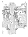
- Fig. 1 shows a part of a transmission 10, which is a housing 12 includes which rotatably receives the shafts 14 and 16.
- the Wave 14 could not be an output shaft of one in FIG. 1 planetary gear shown and the shaft 16 could be a Output shaft of the transmission 10 be.
- the shaft 14 is of the Bearings 18 and 20 stored.
- the shaft 16 is from the bearings 22 and 24 stored.
- a hollow hub gear 26 is on the Shaft 14 mounted.
- the gear 26 includes an inner one Spline or teeth 28, which with an outer Splines 30 of shaft 14 are engaged.
- the gear 26 also includes outer teeth 32.
- a drive gear 40 is rotatable on a portion of the Gear 26 mounted.
- the drive gear 40 includes one Section 42, which has a larger diameter and on which teeth 44 are provided.
- the teeth 44 engage corresponding teeth 46 of the shaft 16.
- the Drive gear 40 further includes a section 48, which has a smaller diameter and on which Teeth 50 are provided which are in the axial direction of the teeth 32 of the gear 26 are arranged adjacent.
- annular shift sleeve 52 is mounted so that it overlaps the teeth 50 and 32.
- Fig. 3 it is shown that the annular shift sleeve 52 a substantially cylindrical Basic body with two sets of in the axial direction spaced teeth 54 and 56, which by a internally running, ring-shaped, in the radial direction extending recess 58 are separated from each other.
- At the outer surface of the ring gear 52 are two Ring webs 60 and 62 provided by an outside extending annular recess 64 separated from each other are.
- there are a large number of teeth 63 formed on the ring land 62 which of one does not shown magnetic speed sensor for detection of available speed can be used.
- the housing 12 has an opening 70 on.
- a plug that can be used especially for maintenance purposes 72 which serves to fix the gear 52 in place removably attached in the opening 70.
- a cylindrical shaft 80 is arranged in the middle and protrudes in the axial direction from cylindrical head portion 74.
- a head start or a nose 82 protrudes in the axial direction from one side 'of the end Surface of the shaft 80 from.
- a threaded centrally located blind hole 84 extends from the outer Surface into the plug 72 to be threaded provided tool - not shown - with which the plug 72 can be manipulated.
- Figure 6 is removable that written instructions on the outer surface of the head portion 74 is provided to assist an operator in aligning the plug 72 in to guide the opening 70.
- Figure 6 and 8 it is shown that two part-circular cutouts 86 and 88 in one radial outer periphery of the surface of the head portion 74 are provided.
- 7 that the nose 82 laterally offset or overall on one side arranged with respect to a central axis 90 of the head section 74 is.
- the nose 82 extends from the left Side of the shaft 80 into the recess 64 of the shift sleeve 52. This causes the shift sleeve 52 to be engaged Position held at which teeth 54 and 56 are engaged with teeth 50 and 32, respectively. In this position the annular gear 52 may have torque from shaft 14 are transmitted to the shaft 16.
- the plug 72 To disconnect the shaft 14 from the shaft 16, the plug 72 removed from the opening 70 and it becomes a not shown Tool inserted through opening 70 into recess 64. With this tool, the shift sleeve 52 is moved such that it slides to the right to that shown in FIG uncoupled or disengaged position to be brought. The plug 72 is then preferably oriented such that the nose 82 is arranged on the right side when the Plug 72 is reinserted into opening 70 so that the nose 82 received by the annular recess 64 can be. The nose 82 holds the shift sleeve 52 in her disengaged position, in which the teeth 56 from the teeth 32 are arranged separately from each other. In this position no torque from shaft 14 to shaft 16 be transmitted.
Landscapes
- Engineering & Computer Science (AREA)
- General Engineering & Computer Science (AREA)
- Mechanical Engineering (AREA)
- Structure Of Transmissions (AREA)
- Gear-Shifting Mechanisms (AREA)
- Mechanical Operated Clutches (AREA)
- One-Way And Automatic Clutches, And Combinations Of Different Clutches (AREA)
- Arrangement And Mounting Of Devices That Control Transmission Of Motive Force (AREA)
Abstract
Description
- Fig. 1
- eine vereinfachte Schnittdarstellung eines erfindungsgemäßen Ausführungsbeispiels einer Vorrichtung zum Unterbrechen einer Drehmomentverbindung eines Getriebes, wobei das Getriebe in einem gekuppelten Zustand gezeigt ist,
- Fig. 2
- das Ausführungsbeispiel gemäß Fig. 1, wobei das Getriebe in einem abgekuppelten Zustand gezeigt ist,
- Fig. 3
- eine Schnittansicht eines Teils einer in Fig. 1 gezeigten Schaltmuffe,
- Fig. 4
- eine perspektivische Ansicht der Schaltmuffe aus Fig. 1,
- Fig. 5
- eine perspektivische Ansicht des Stöpsels zur Lagefixierung des ringförmigen Zahnrads aus Fig. 1,
- Fig. 6
- eine Draufsicht des Stöpsels zur Lagefixierung des ringförmigen Zahnrads aus Fig. 1,
- Fig. 7
- eine Schnittansicht entlang der Linien 7-7 aus Fig. 6 und
- Fig. 8
- eine Schnittansicht entlang der Linie 8-8 aus Fig. 6.
Claims (10)
- Vorrichtung zum Unterbrechen einer Drehmomentverbindung eines Getriebes (10), mit welcher eine Übertragung eines Drehmoments von einer ersten Welle (14) auf eine zweite Welle (16) des Getriebes (10) steuerbar ist, mit einem Gehäuse (12), einem Kupplungselement (52) und einem Stöpsel (72), wobei das Gehäuse (12) eine erste Welle (14) und eine zweite Welle (16) drehbar aufnimmt und eine Öffnung (70) aufweist, wobei das Kupplungselement (52) von einer eingerückten Position, in welcher das Kupplungselement (52) die erste Welle (14) mit der zweiten Welle (16) kuppelt, in eine ausgerückte Position verbringbar ist, in welcher die erste Welle (14) von der zweiten Welle (16) abgekuppelt ist, wobei der Stöpsel (72) in der Öffnung (70) befestigbar und mit dem Kupplungselement (52) in Eingriff bringbar ist, und wobei der Stöpsel (72) von einer ersten Position, in welcher der Stöpsel (72) das Kupplungselement (52) in der eingerückten Position hält, zu einer zweiten Position verbringbar ist, in welcher der Stöpsel (72) das Kupplungselement (52) in der ausgerückten Position hält.
- Vorrichtung nach Anspruch 1, dadurch gekennzeichnet, dass das Kupplungselement (52) ein hohles, ringförmiges Bauteil aufweist, welches eine der beiden Wellen (14, 16) aufnimmt.
- Vorrichtung nach Anspruch 1 oder 2, dadurch gekennzeichnet, dass der Stöpsel (72) einen im Wesentlichen zylindrischen Kopfabschnitt (74) aufweist, welcher von der Öffnung (70) aufnehmbar ist, und dass der Stöpsel (72) eine Nase (82) aufweist, welche von dem Kopfabschnitt (74) abragt, wobei die Nase (82) mit dem Kupplungselement (52) in Eingriff bringbar ist, und wobei die Nase (82) seitlich versetzt zu einer Mittelachse (90) angeordnet ist.
- Vorrichtung nach einem der Ansprüche 1 bis 3, dadurch gekennzeichnet, dass ein Antriebszahnrad (40) drehbar auf der ersten Welle (14) angeordnet ist, wobei das Antriebszahnrad (40) einen ersten Satz von Zähnen (44) aufweist, welche im kämmenden Eingriff mit hierzu korrespondierenden, an der zweiten Welle (16) vorgesehenen Zähnen (46) stehen, und wobei das Antriebszahnrad (40) einen zweiten Satz von Zähnen (50) aufweist.
- Vorrichtung nach einem der Ansprüche 1 bis 4, dadurch gekennzeichnet, dass ein hohles Nabenzahnrad (26) auf der ersten Welle (14) drehfest angebracht ist, welches einen Satz von Zähnen (32) aufweist.
- Vorrichtung nach Anspruch 4 oder 5, dadurch gekennzeichnet, dass das Kupplungselement (52) eine Schaltmuffe aufweist, welches mit dem Antriebszahnrad (40) und - vorzugsweise selektierbar - mit dem Nabenzahnrad (26) in Eingriff bringbar ist, wobei die Schaltmuffe eine ringförmige Ausnehmung (58) aufweist, welche einen Teil des Stöpsels (72) aufnimmt, insbesondere die Nase (82) des Stöpsels (72).
- Vorrichtung nach einem der Ansprüche 4 bis 6, dadurch gekennzeichnet, dass das Kupplungselement (52) mit dem Antriebszahnrad (40) und dem Nabenzahnrad (26) in Eingriff bringbar ist, wobei das Kupplungselement (52) von einer eingerückten Position, in welcher das Kupplungselement (52) die Zähne (32) des Nabenzahnrads (26) mit dem zweiten Satz von Zähnen (50) des Antriebszahnrads (40) kuppelt, zu einer ausgerückten Position verbringbar ist, in welcher die Zähne (32) des Zahnrads (26) mit dem zweiten Satz von Zähnen (50) des Antriebszahnrads (40) abgekuppelt sind.
- Vorrichtung nach einem der Ansprüche 1 bis 7, dadurch gekennzeichnet, dass das Kupplungselement (52) ein hohles, ringförmiges Bauteil aufweist, welches einen ersten Satz von inneren Zähnen (54) und einen davon in axialer Richtung beabstandet angeordneten zweiten Satz von inneren Zähnen (56) aufweist, wobei eine äußere Oberfläche des ringförmigen Bauteils einen ersten und einen zweiten Ringsteg (60, 62) aufweist, welche durch eine außen verlaufende, ringförmige, sich in radialer Richtung erstreckende Ausnehmung (64) voneinander beabstandet angeordnet sind, wobei der erste Satz der inneren Zähne (54) mit dem zweiten Satz der Zähne (50) des Antriebszahnrads (40) kämmt, und wobei der zweite Satz der inneren Zähne (56) mit den Zähnen (32) eines Eingangswellenzahnrades, vorzugsweise des Nabenzahnrads (26) selektierbar kämmt, wobei vorzugsweise eine ringförmige Ausnehmung (58) zwischen dem ersten und dem zweiten Satz von inneren Zähnen (54, 56) vorgesehen ist.
- Vorrichtung nach Anspruch 8, dadurch gekennzeichnet, dass die ringförmige Ausnehmung (58) des Kupplungselements (52) die Zähne (32) des Antriebszahnrads (26) aufnimmt, wenn das Kupplungselement (52) in seiner ausgerückten Position ist.
- Vorrichtung nach einem der Ansprüche 1 bis 9, dadurch gekennzeichnet, dass der Stöpsel (72) in einer äußeren Oberfläche eine Apertur (84) aufweist, welche ein Werkzeug aufnehmen kann.
Applications Claiming Priority (2)
| Application Number | Priority Date | Filing Date | Title |
|---|---|---|---|
| US10/217,298 US7121395B2 (en) | 2002-08-12 | 2002-08-12 | Torque disconnect mechanism |
| US217298 | 2002-08-12 |
Publications (2)
| Publication Number | Publication Date |
|---|---|
| EP1389698A2 true EP1389698A2 (de) | 2004-02-18 |
| EP1389698A3 EP1389698A3 (de) | 2006-02-08 |
Family
ID=30770616
Family Applications (1)
| Application Number | Title | Priority Date | Filing Date |
|---|---|---|---|
| EP03018077A Withdrawn EP1389698A3 (de) | 2002-08-12 | 2003-08-08 | Vorrichtung zum Unterbrechen einer Drehmomentverbindung eines Getriebes |
Country Status (4)
| Country | Link |
|---|---|
| US (1) | US7121395B2 (de) |
| EP (1) | EP1389698A3 (de) |
| BR (1) | BR0302670A (de) |
| CA (1) | CA2436002C (de) |
Cited By (1)
| Publication number | Priority date | Publication date | Assignee | Title |
|---|---|---|---|---|
| DE102007041849A1 (de) * | 2007-09-03 | 2009-03-05 | Robert Bosch Gmbh | Kupplungsvorrichtung, insbesondere für eine Sensoreinrichtung |
Families Citing this family (2)
| Publication number | Priority date | Publication date | Assignee | Title |
|---|---|---|---|---|
| US7975796B2 (en) * | 2008-06-30 | 2011-07-12 | Chrysler Group Llc | Reduced friction differential disconnect for a motor vehicle |
| CN104471284B (zh) * | 2012-06-25 | 2017-08-22 | 沃尔沃拉斯特瓦格纳公司 | 双离合变速器 |
Family Cites Families (12)
| Publication number | Priority date | Publication date | Assignee | Title |
|---|---|---|---|---|
| US2685210A (en) * | 1951-01-27 | 1954-08-03 | Harry F Heisler | Overdrive system |
| DE2246661A1 (de) * | 1972-09-22 | 1974-03-28 | Porsche Ag | Lenkanordnung fuer kraftfahrzeuge |
| US4244455A (en) * | 1978-10-17 | 1981-01-13 | The United States Of America As Represented By The Secretary Of The Navy | Rotary shaft decoupling mechanism |
| US4566566A (en) * | 1983-09-19 | 1986-01-28 | Societe Alsacienne De Construction De Material Textile | Device for temporarily uncoupling two coaxial rotating elements |
| DE3405038A1 (de) * | 1984-02-13 | 1985-08-14 | Zahnradfabrik Altona-Elbe Hans Meyer GmbH & Co KG, 2000 Hamburg | Schaltkupplung |
| JPH01144552U (de) * | 1988-03-29 | 1989-10-04 | ||
| DE4020959A1 (de) | 1989-07-05 | 1991-01-17 | Zahnradfabrik Friedrichshafen | Vielstufiges zahnraederwechselgetriebe |
| US5085305A (en) * | 1990-12-10 | 1992-02-04 | Cheng Yen Feng | Cam-operated, positive clutch with electromagnetic actuator |
| DE29509232U1 (de) | 1995-06-03 | 1995-08-17 | Siebenhaar Antriebstechnik GmbH, 34369 Hofgeismar | Schnellaufendes, mehrstufiges Planetenradschaltgetriebe |
| US5560432A (en) * | 1995-07-28 | 1996-10-01 | Conte; Ernest R. | Steering clutch for small agricultural implements |
| US6378393B1 (en) | 2000-05-19 | 2002-04-30 | Kelsey-Hayes Company | Method and apparatus for manually shifting an electronically controlled transmission |
| US6648118B1 (en) * | 2002-07-01 | 2003-11-18 | Kwang Yang Motor Co., Ltd. | Clutch device for an electric motor-driven wheeled vehicle |
-
2002
- 2002-08-12 US US10/217,298 patent/US7121395B2/en not_active Expired - Fee Related
-
2003
- 2003-07-25 CA CA002436002A patent/CA2436002C/en not_active Expired - Fee Related
- 2003-08-05 BR BR0302670-1A patent/BR0302670A/pt not_active IP Right Cessation
- 2003-08-08 EP EP03018077A patent/EP1389698A3/de not_active Withdrawn
Non-Patent Citations (1)
| Title |
|---|
| None |
Cited By (1)
| Publication number | Priority date | Publication date | Assignee | Title |
|---|---|---|---|---|
| DE102007041849A1 (de) * | 2007-09-03 | 2009-03-05 | Robert Bosch Gmbh | Kupplungsvorrichtung, insbesondere für eine Sensoreinrichtung |
Also Published As
| Publication number | Publication date |
|---|---|
| US7121395B2 (en) | 2006-10-17 |
| BR0302670A (pt) | 2004-12-28 |
| EP1389698A3 (de) | 2006-02-08 |
| US20040026205A1 (en) | 2004-02-12 |
| CA2436002A1 (en) | 2004-02-12 |
| CA2436002C (en) | 2007-07-10 |
Similar Documents
| Publication | Publication Date | Title |
|---|---|---|
| DE3216203C2 (de) | Vierradantrieb für Fahrzeuge | |
| DE102009017537B3 (de) | Doppelkupplungsgetriebe mit drei Triebwellen | |
| DE102014103485B4 (de) | Achsenanordnung mit drehmomentverteilungsantriebsmechanismus | |
| DE2855797C3 (de) | Zahnärztliche Handstückanordnung | |
| DE69107008T2 (de) | Drehantrieb mit innenverzahntem Planetenrad-Untersetzungsgetriebe und Freilaufeinrichtung. | |
| DE69404611T2 (de) | Einbauanordnung eines Rücklaufrades | |
| DE202010017923U1 (de) | Winkeltriebanordnung | |
| DE2924004C2 (de) | Gehäuse für ein Kraftfahrzeuggetriebe | |
| DE102016122262A1 (de) | Nebenabtriebseinheit mit Sperrdifferential | |
| DE19811874A1 (de) | Anbringstruktur für Rückwärtsgang-Zwischenrad in einem Schaltgetriebe | |
| DE2930950B1 (de) | Fahrzeugwechselgetriebe,insbesondere fuer Ackerschlepper | |
| DE2758394C2 (de) | Sperreinrichtung für ein Wechselgetriebe mit Sperrsynchronisation | |
| AT413747B (de) | Winkelgetriebe mit integrierter drehspielkupplung | |
| DE69908758T2 (de) | Sechsganghandschaltgetriebe mit differenzial | |
| DE2707699B2 (de) | Zahnradgetriebe mit veränderbarer Übersetzung | |
| DE102018207970B4 (de) | Schaltanordnung sowie Getriebe | |
| DE3306131A1 (de) | Kupplungsanordnung an einem getriebe, insbesondere schiffsgetriebe | |
| EP1443245B1 (de) | Kraftfahrzeuggetriebe | |
| EP1389698A2 (de) | Vorrichtung zum Unterbrechen einer Drehmomentverbindung eines Getriebes | |
| EP3368799B1 (de) | Schaltvorrichtung und antriebseinheit für ein kraftfahrzeug | |
| DE3823785C2 (de) | ||
| DE20212094U1 (de) | Antriebsstrang für ein Allrad-Kraftfahrzeug | |
| DE102010052746B4 (de) | Kompaktes Schaltgetriebe | |
| DE10307178B4 (de) | Kraftfahrzeuggetriebe | |
| DE4401491A1 (de) | Antrieb mit Motor und Steckritzel |
Legal Events
| Date | Code | Title | Description |
|---|---|---|---|
| PUAI | Public reference made under article 153(3) epc to a published international application that has entered the european phase |
Free format text: ORIGINAL CODE: 0009012 |
|
| AK | Designated contracting states |
Kind code of ref document: A2 Designated state(s): AT BE BG CH CY CZ DE DK EE ES FI FR GB GR HU IE IT LI LU MC NL PT RO SE SI SK TR |
|
| AX | Request for extension of the european patent |
Extension state: AL LT LV MK |
|
| PUAL | Search report despatched |
Free format text: ORIGINAL CODE: 0009013 |
|
| AK | Designated contracting states |
Kind code of ref document: A3 Designated state(s): AT BE BG CH CY CZ DE DK EE ES FI FR GB GR HU IE IT LI LU MC NL PT RO SE SI SK TR |
|
| AX | Request for extension of the european patent |
Extension state: AL LT LV MK |
|
| 17P | Request for examination filed |
Effective date: 20060808 |
|
| AKX | Designation fees paid |
Designated state(s): DE FR GB IT |
|
| GRAP | Despatch of communication of intention to grant a patent |
Free format text: ORIGINAL CODE: EPIDOSNIGR1 |
|
| RIC1 | Information provided on ipc code assigned before grant |
Ipc: F16H 63/04 20060101AFI20070209BHEP |
|
| STAA | Information on the status of an ep patent application or granted ep patent |
Free format text: STATUS: THE APPLICATION IS DEEMED TO BE WITHDRAWN |
|
| 18D | Application deemed to be withdrawn |
Effective date: 20070703 |