EP1389574A1 - Steering gear with variable maximum stroke - Google Patents
Steering gear with variable maximum stroke Download PDFInfo
- Publication number
- EP1389574A1 EP1389574A1 EP03292026A EP03292026A EP1389574A1 EP 1389574 A1 EP1389574 A1 EP 1389574A1 EP 03292026 A EP03292026 A EP 03292026A EP 03292026 A EP03292026 A EP 03292026A EP 1389574 A1 EP1389574 A1 EP 1389574A1
- Authority
- EP
- European Patent Office
- Prior art keywords
- rack
- steering mechanism
- housing
- steering
- wedge
- Prior art date
- Legal status (The legal status is an assumption and is not a legal conclusion. Google has not performed a legal analysis and makes no representation as to the accuracy of the status listed.)
- Withdrawn
Links
Images


Classifications
-
- B—PERFORMING OPERATIONS; TRANSPORTING
- B62—LAND VEHICLES FOR TRAVELLING OTHERWISE THAN ON RAILS
- B62D—MOTOR VEHICLES; TRAILERS
- B62D3/00—Steering gears
- B62D3/02—Steering gears mechanical
- B62D3/12—Steering gears mechanical of rack-and-pinion type
Definitions
- the invention relates to a steering mechanism for motor vehicle.
- the invention relates more particularly to a mechanism motor vehicle steering system comprising a steering bar rack which is slidably mounted transversely in a rack housing, generally tubular, and which is susceptible to drive at least one steering bar connected to a wheel vehicle steering, of the type in which the rack bar carries two stops each of which is capable of cooperating with one end of the housing to determine, in both directions, a maximum full stroke of the rack bar relative to to the rack housing.
- Motor vehicles generally include the front, two steering wheels each housed under a wing of the vehicle, on either side of the engine compartment. It is necessary to provide a wheel housing between the wings and the motor whose dimensions allow pivoting and vertical travel, or pumping, maximum of the wheels so that these do not come into contact with an element of vehicle structure or bodywork.
- the maximum vertical travel is determined by the suspension mechanism that connects the wheels to the structure of the vehicle and which is intended in particular to dampen the oscillations of the body of the vehicle when it is traveling on a road bumpy at a speed above a speed threshold, by example 15 km / h.
- the maximum pivoting, or turning, of the wheels is determined by the steering mechanism.
- the wheel housing is notably dimensioned in forecast of extreme driving conditions that only happen very rarely during the life of the vehicle. So, it is rare and risky that a driver turns the wheels as much as possible while the vehicle speed is greater than a threshold speed, for example 15 km / h. Under these conditions, the wheel which is turned at maximum, is likely to have vertical travel maximum.
- the wheel can also occasionally be fitted with chains to facilitate driving on snow.
- the width and the total height of the wheel is then increased by the thickness Chains.
- the wheel housing must therefore be sufficiently spacious to avoid chaffing of chains against structural or body elements of the vehicle.
- a portion of the wheel housing is thus often unused but remains essential. This portion of housing however encroaches on the engine compartment space.
- the present invention provides a steering mechanism of the type described above, characterized in that it comprises means controlled to vary the length of the stroke maximum sliding of the rack bar relative to the rack housing.
- Figure 1 is a schematic view which represents a motor vehicle 10 which here has a wheel 12a housed in a wheel housing 14, under a left front wing 16.
- the wheel housing 14 is delimited upwards by the wing front left 16 and laterally to the right by a engine compartment 18.
- the motor vehicle 10 here comprises a mechanism for direction 20 which is produced according to the state of the art and which is located in the engine compartment 18 between the two wheels guidelines front left 12a and front right (not shown) which it controls the simultaneous pivoting relative to the vehicle around a substantially vertical axis.
- the steering mechanism 20 in FIG. 3 comprises a pinion 22 which is controlled by a steering wheel (not represented).
- the pinion 22 has a toothing 24 which is intended to cooperate with notches 26 of a rack bar transverse 28.
- the rack bar 28 is mounted sliding transversely in a rack housing 30 generally tubular.
- the rack housing 30 is here fixed relative to the vehicle structure 10. It has two lateral ends left 32a and right 32b open of which exceed two extreme sections left 34a and right 34b of the bar rack 28 according to the orientation of figure 3.
- An axial face outer 35 of the casing 30 here comprises a housing 36 in which the pinion 22 is received.
- the extreme sections 34a and 34b of the bar rack 28 are generally symmetrical with respect to a longitudinal and transverse median plane P which divides the bar rack 28 in two equal parts left and right.
- a steering rod 38a, 38b is mounted articulated by a ball 40a, 40b on one end 42a, 42b of the bar rack 18.
- the steering bar 38a, 38b connects the steering bar rack 28 with a steering wheel 12a.
- the end section 34a, 34b of the rack bar 28 here carries a stop 44a, 44b which is oriented transversely in look of the lateral end 32a, 32b of the casing 30 with which the stop 44a, 44b is intended to cooperate.
- the stop 44a, 44b is advantageously made of elastomeric material in order to cushion a possible shock during contact between the stop 44a, 44b and the casing 30.
- the stops 44a and 44b determine, in the two sense, a maximum stroke of length L from the bar rack 28 with respect to rack housing 30.
- the driver When changing direction, the driver turns the steering wheel which controls the rotation of the pinion 22 which causes the rack bar 28 to slide in relation to to the rack housing 30.
- the rack bar 28 pulls or pushes the steering rods 38a and 38b which rotate the steered wheels.
- the maximum steering of the steered wheels is determined by the length L of the travel of the rack bar 28 by relative to the rack housing 30. So when the driver controls the maximum steering of the wheels, the rack 28 slides in the rack housing 30 up to that one of the stops 44a or 44b comes into contact with one of the lateral ends 32a or 32b of the casing 30 respectively.
- FIG. 4 shows the consequence of a maximum steering to the left on the steering wheel 12a.
- the steering being the same whatever the conditions of rolling of the vehicle 10, it is necessary to preserve a internal lateral space 43 between the wheel 12a and the compartment motor 18 for the case in which the wheel 12a is equipped with chains.
- Figure 4 also shows in broken lines the wheel 12a in the maximum vertical deflection and deflection position. It is then necessary to provide an upper space 47 for this rare configuration, but possible.
- FIG. 5 shows a steering mechanism 45 made according to the teachings of the invention.
- This mechanism 45 is generally similar to that described above which is shown in Figure 3.
- This steering mechanism 45 comprises two additional retractable wedges 46a and 46b which are arranged symmetrically with respect to the median plane P. Each wedge is controlled between a retracted position and a position active.
- Each wedge 46a, 46b has the overall shape of an "L" which here has a first fixing end 48a, 48b which is pivotally mounted on the axial wall at one end of the housing around an axis A, B which is orthogonal to the transverse axis of the rack bar 28.
- a first fixing branch 50a, 50b of the "L” extends from the fixing end 48a, 48b of orthogonal to both the pivot axis A, B of the wedge 46a, 46b and to the transverse axis of sliding of the bar rack 28.
- the first fixing branch 50a, 50b carries a second free branch 52a, 52b of the "L” which extends here perpendicular to the first branch 50a, 50b in the direction from the end of the rack bar 42a, 42b and which forms a corner 54a, 54b with the first attachment branch 50a, 50b.
- the fixing branch 50a, 50b of the wedge 46a, 46b is substantially pressed against the axial wall 35 of the casing 30.
- the corner 54a, 54b of the wedge 46a, 46b wife then substantially the lateral end 32a, 32b of the casing 30 of so that the free branch 52a, 52b of the wedge 46a, 46b is interposed between the lateral end 32a, 32b of the casing 30 and the stop 44a, 44b of the rack bar 28.
- a face 56a, 56b of the free branch 52a, 52b opposite of the stop 44a, 44b forms a stopper intended to cooperate with the stop 44a, 44b.
- the displacements of the wedge 46a, 46b between the position retracted and the active position are for example controlled at by means of an electric motor.
- the movements of the shim 46a, 46b are controlled by means of an electromagnet between the retracted position and the active position.
- Wedge 46a, 46b is returned elastically to one of the retracted positions or active, for example towards the retracted position.
- the steering mechanism 45 works like the steering mechanism direction 20 produced according to the state of the art.
- the race maximum of the rack bar is then complete and has a length L in both directions.
- the displacements of the wedge 46a, 46b between its position retracted and its active position are notably controlled by function of a parameter representative of the driving speed of the vehicle. So when the vehicle speed 10 exceeds one speed threshold, for example 15 km / h, the chocks are pivoted in active position.
- the left shims 46a and right 46b pivot around their respective axis A, B in a clockwise and anti-clockwise direction respectively, indicated by the arrows Fa and Fb in FIG. 5.
- the maximum stroke of the rack bar 28 thus has a reduced length L r in both directions.
- the invention thus makes it possible to limit the pivoting of the wheels steering when the vehicle 10 is traveling at a speed higher than the speed threshold. Thanks to this invention, the wheel cannot moment reach the area 47 of the wheel housing illustrated in the figure 7. Indeed, if the vehicle is traveling at a speed lower than the speed threshold, the wheel does not have a maximum vertical travel when it encounters a bump. However, when the vehicle is traveling at a speed higher than the speed threshold, the meeting a bump is likely to result in a deflection vertical maximum, but the wheel cannot turn as much as possible.
- the displacements of the shim 46a, 46b are in particular controlled as a function of the presence of chain on the steering wheels of the vehicle 10.
- the shims bearing the buffers are slidably mounted relative to the steering housing in a generally radial direction.
- the rack bar 28 has a notch transverse 58 which is here located on a part 60 of the bar rack 28 which is contained in the rack housing 30.
- the rack housing 30 has a through hole 62 of a wedge 46 sliding in a radial direction which is here vertical.
- the wedge 46 has two transverse faces 56a, 56b, forming buffers, which are intended to cooperate with two faces internal transverse 64a, 64b of the notch 58 forming stop faces.
- FIG. 7 illustrates here the shim 46 in the active position.
- the retracted position of the wedge 46 is obtained by sliding the latter down, in the direction indicated by the arrow F of FIG. 7.
- the shim 46 is controlled between its position active and its position retracted by means similar to those described in the previous embodiments.
- the stroke transverse of the rack bar 28 has a reduced length Lr in both directions. Indeed, if the driver tries to turn the wheels 12a as far as possible, the stop face 64a, 64b of the notch cooperates with the stopper 56a, 56b of the wedge to limit the sliding of the rack bar 28 relative to the casing 30.
- a signal is emitted, for example by a position sensor, when the shim 46 or the shims 46a and 46b are in the active position, in order to inform the driver of the vehicle's turning radius limitation, by example by illuminating an indicator light located on the vehicle dashboard.
Landscapes
- Engineering & Computer Science (AREA)
- Chemical & Material Sciences (AREA)
- Combustion & Propulsion (AREA)
- Transportation (AREA)
- Mechanical Engineering (AREA)
- Steering Control In Accordance With Driving Conditions (AREA)
Abstract
Description
L'invention concerne un mécanisme de direction de véhicule automobile.The invention relates to a steering mechanism for motor vehicle.
L'invention concerne plus particulièrement un mécanisme de direction de véhicule automobile comportant une barre de crémaillère qui est montée coulissante transversalement dans un carter de crémaillère, globalement tubulaire, et qui est susceptible d'entraíner au moins une barre de direction reliée à une roue directrice du véhicule, du type dans lequel la barre de crémaillère porte deux butées dont chacune est susceptible de coopérer avec une extrémité du carter pour déterminer, dans les deux sens, une course maximale complète de la barre de crémaillère par rapport au carter de crémaillère.The invention relates more particularly to a mechanism motor vehicle steering system comprising a steering bar rack which is slidably mounted transversely in a rack housing, generally tubular, and which is susceptible to drive at least one steering bar connected to a wheel vehicle steering, of the type in which the rack bar carries two stops each of which is capable of cooperating with one end of the housing to determine, in both directions, a maximum full stroke of the rack bar relative to to the rack housing.
Les véhicules automobiles comportent, généralement à l'avant, deux roues directrices chacune logée sous une aile du véhicule, de part et d'autre du compartiment moteur. Il est nécessaire de prévoir un logement de roue entre les ailes et le moteur dont les dimensions permettent le pivotement et le débattement vertical, ou pompage, maximum des roues afin que ces dernières ne viennent pas en contact avec un élément de structure ou de carrosserie du véhicule.Motor vehicles generally include the front, two steering wheels each housed under a wing of the vehicle, on either side of the engine compartment. It is necessary to provide a wheel housing between the wings and the motor whose dimensions allow pivoting and vertical travel, or pumping, maximum of the wheels so that these do not come into contact with an element of vehicle structure or bodywork.
Le débattement vertical maximum est déterminé par le mécanisme de suspension qui relie les roues à la structure du véhicule et qui est notamment destiné à amortir les oscillations de la caisse du véhicule lorsque ce dernier roule sur une route cahoteuse à une vitesse supérieur à un seuil de vitesse, par exemple 15 km/h.The maximum vertical travel is determined by the suspension mechanism that connects the wheels to the structure of the vehicle and which is intended in particular to dampen the oscillations of the body of the vehicle when it is traveling on a road bumpy at a speed above a speed threshold, by example 15 km / h.
Le pivotement, ou braquage, maximum des roues est déterminé par le mécanisme de direction.The maximum pivoting, or turning, of the wheels is determined by the steering mechanism.
Le logement de roue est notamment dimensionné en prévision de conditions de conduite extrêmes qui n'arrivent que très rarement durant la vie du véhicule. Ainsi, il est rare et risqué qu'un conducteur braque au maximum les roues alors que la vitesse du véhicule est supérieure à une vitesse de seuil, par exemple 15 km/h. Dans ces conditions, la roue qui est braquée au maximum, est susceptible d'avoir un débattement vertical maximum.The wheel housing is notably dimensioned in forecast of extreme driving conditions that only happen very rarely during the life of the vehicle. So, it is rare and risky that a driver turns the wheels as much as possible while the vehicle speed is greater than a threshold speed, for example 15 km / h. Under these conditions, the wheel which is turned at maximum, is likely to have vertical travel maximum.
La roue peut aussi occasionnellement être équipée de chaínes pour faciliter la conduite sur de la neige. La largeur et la hauteur totales de la roue sont alors augmentées de l'épaisseur des chaínes. Le logement de roue doit donc être suffisamment spacieux pour éviter le frottement des chaínes contre des éléments de structure ou de carrosserie du véhicule.The wheel can also occasionally be fitted with chains to facilitate driving on snow. The width and the total height of the wheel is then increased by the thickness Chains. The wheel housing must therefore be sufficiently spacious to avoid chaffing of chains against structural or body elements of the vehicle.
Une portion du logement de roue est ainsi souvent inutilisée mais demeure indispensable. Cette portion de logement empiète cependant dans l'espace du compartiment moteur.A portion of the wheel housing is thus often unused but remains essential. This portion of housing however encroaches on the engine compartment space.
Pour résoudre ce problème, il est connu de réduire la course maximale de coulissement de la barre de crémaillère pour certaines conditions de roulement du véhicule. Le pivotement maximum des roues directrices est ainsi réduit, sans gêner le conducteur lorsque les conditions de roulement du véhicule sont normales.To solve this problem, it is known to reduce the maximum sliding stroke of the rack bar for certain vehicle rolling conditions. The pivoting maximum of the steered wheels is thus reduced, without hampering the driver when the vehicle's driving conditions are normal.
Cependant, les solutions existantes ne concernent que des mécanismes de direction commandés ou assistés électriquement.However, the existing solutions only concern controlled or assisted steering mechanisms electrically.
La présent invention propose un mécanisme de direction du type décrit précédemment, caractérisé en ce qu'il comporte des moyens commandés pour faire varier la longueur de la course maximale de coulissement de la barre de crémaillère par rapport au carter de crémaillère.The present invention provides a steering mechanism of the type described above, characterized in that it comprises means controlled to vary the length of the stroke maximum sliding of the rack bar relative to the rack housing.
Selon d'autres caractéristiques de l'invention :
- le mécanisme de direction comporte au moins une cale
escamotable dont les déplacements sont commandés entre :
- une position active dans laquelle deux faces transversales et opposées formant butoir, qui sont portées par ladite cale, sont susceptibles de coopérer chacune avec une face d'arrêt transversale et opposée qui est portée par la barre de crémaillère, pour déterminer une course maximale réduite dans les deux sens de la barre de crémaillère par rapport au carter de crémaillère ; et
- une position escamotée dans laquelle la course maximale de la barre de crémaillère est complète ;
- le mécanisme de direction comporte deux cales escamotables qui comportent chacune une face formant butoir et dont chacune, en position active, est intercalée entre une des extrémités du carter de crémaillère et une des butées de la crémaillère formant face d'arrêt ;
- la crémaillère comporte une encoche transversale dont les faces latérales et opposées constituent les faces d'arrêt, et en ce qu'il comporte une cale escamotable dont les deux faces transversales et opposées forment butoirs ;
- la cale est montée articulée par rapport au carter de crémaillère autour d'un axe orthogonal à l'axe longitudinal du carter ;
- la butée escamotable est montée coulissante par rapport au carter de crémaillère selon une direction sensiblement radiale ;
- les déplacements de la cale entre la position escamotée et la position active sont commandés au moyen d'un électroaimant ou d'un moteur électrique ;
- la cale est rappelée élastiquement vers sa position escamotée ;
- les déplacements de la cale entre sa position escamotée et sa position active sont commandés en fonction d'un paramètre représentatif de la vitesse du véhicule ;
- les déplacements de la cale entre sa position escamotée et sa position active sont commandés en fonction de la présence de chaínes sur la roue directrice du véhicule.
- le mécanisme de direction comporte un dispositif pour émettre un signal représentatif de la position active de la cale escamotable.
- the steering mechanism comprises at least one retractable wedge whose movements are controlled between:
- an active position in which two transverse and opposite faces forming a stopper, which are carried by said wedge, are each capable of cooperating with a transverse and opposite stop face which is carried by the rack bar, to determine a reduced maximum stroke in both directions of the rack bar with respect to the rack housing; and
- a retracted position in which the maximum stroke of the rack bar is complete;
- the steering mechanism comprises two retractable shims which each have a face forming a stopper and each of which, in the active position, is interposed between one of the ends of the rack housing and one of the stops of the rack forming stop face;
- the rack has a transverse notch whose lateral and opposite faces constitute the stop faces, and in that it comprises a retractable wedge whose two transverse and opposite faces form buffers;
- the shim is mounted articulated relative to the rack housing around an axis orthogonal to the longitudinal axis of the housing;
- the retractable stop is slidably mounted relative to the rack housing in a substantially radial direction;
- the movements of the wedge between the retracted position and the active position are controlled by means of an electromagnet or an electric motor;
- the wedge is resiliently returned to its retracted position;
- the movements of the wedge between its retracted position and its active position are controlled as a function of a parameter representative of the speed of the vehicle;
- the movements of the wedge between its retracted position and its active position are controlled according to the presence of chains on the steering wheel of the vehicle.
- the steering mechanism includes a device for transmitting a signal representative of the active position of the retractable wedge.
D'autres caractéristiques et avantages de l'invention apparaítront au cours de la lecture de la description détaillée qui suit pour la compréhension de laquelle on se reportera aux dessins annexés parmi lesquels :
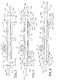
- la figure 1 est une vue schématique d'un véhicule automobile équipé d'un mécanisme de direction à crémaillère ;
- la figure 2 est une vue en section schématique de derrière de la partie avant gauche du véhicule automobile représenté à la figure 1 selon le plan de coupe 2-2, le véhicule étant ici équipé d'un mécanisme de direction à crémaillère qui est réalisé selon l'état de la technique et qui est notamment relié à une roue directrice avant gauche ;
- la figure 3 est une vue de détail à plus grande échelle du mécanisme de direction à crémaillère de la figure 2 ;
- la figure 4 est la même vue que la figure 2 dans laquelle la roue directrice avant gauche est en position de braquage maximum vers la gauche ;
- la figure 5 est une vue analogue à celle de la figure 3 dans laquelle le mécanisme de direction est équipé de cales réalisées selon les enseignements de l'invention ;
- la figure 6 est la même vue que la figure 5 dans laquelle les cales sont en position active et la barre de crémaillère est en position de coulissement maximum vers la droite par rapport au carter de crémaillère ;
- la figure 7 est la même vue que la figure 2 dans laquelle le véhicule est équipé du mécanisme de direction représenté à la figure 6 ;
- la figure 8 représente une variante de réalisation du mécanisme de direction réalisé selon les enseignements de l'invention.
- Figure 1 is a schematic view of a motor vehicle equipped with a rack and pinion steering mechanism;
- Figure 2 is a schematic rear sectional view of the left front part of the motor vehicle shown in Figure 1 according to the section plane 2-2, the vehicle here being equipped with a rack-and-pinion steering mechanism which is produced according to the state of the art and which is in particular connected to a front left steering wheel;
- Figure 3 is an enlarged detail view of the rack and pinion steering mechanism of Figure 2;
- Figure 4 is the same view as Figure 2 in which the front left steering wheel is in the maximum turning position to the left;
- Figure 5 is a view similar to that of Figure 3 in which the steering mechanism is fitted with shims made according to the teachings of the invention;
- Figure 6 is the same view as Figure 5 wherein the shims are in the active position and the rack bar is in the maximum sliding position to the right relative to the rack housing;
- Figure 7 is the same view as Figure 2 in which the vehicle is equipped with the steering mechanism shown in Figure 6;
- FIG. 8 represents an alternative embodiment of the steering mechanism produced according to the teachings of the invention.
Dans la description qui va suivre, on adoptera à titre non limitatif une orientation longitudinale, verticale et transversale selon l'orientation traditionnellement utilisée dans l'automobile et indiquée par le trièdre L, V, T de la figure 1. In the description which follows, we will adopt as limiting a longitudinal, vertical and transverse orientation according to the orientation traditionally used in the automobile and indicated by the trihedron L, V, T of figure 1.
Dans la description, des éléments identiques, analogues ou similaires seront désignés par les mêmes références.In the description, identical, analogous elements or similar will be designated by the same references.
La figure 1 est une vue schématique qui représente un
véhicule automobile 10 qui comporte ici une roue 12a logée dans
un logement de roue 14, sous une aile avant gauche 16.Figure 1 is a schematic view which represents a
Le logement de roue 14 est délimité vers le haut par l'aile
avant gauche 16 et latéralement vers la droite par un
compartiment moteur 18.The
Le véhicule automobile 10 comporte ici un mécanisme de
direction 20 qui est réalisé selon l'état de la technique et qui est
situé dans le compartiment moteur 18 entre les deux roues
directrices avant gauche 12a et avant droite (non représentée)
dont il commande le pivotement simultané par rapport au véhicule
autour d'un axe sensiblement vertical.The
Le mécanisme de direction 20 à la figure 3 comporte un
pignon 22 qui est commandé par un volant de direction (non
représenté). Le pignon 22 comporte une denture 24 qui est
destinée à coopérer avec des crans 26 d'une barre de crémaillère
transversale 28. La barre de crémaillère 28 est montée
coulissante transversalement dans un carter de crémaillère 30
globalement tubulaire.The
Dans les paragraphes qui suivent, deux éléments
identiques du mécanisme de direction 20 et agencés symétriquement
à la partie à gauche du plan P et à droite du plan P,
respectivement, sont désignés par un même chiffre de référence
suivi respectivement de la lettre « a » et « b ».In the following paragraphs, two elements
identical to the
Le carter de crémaillère 30 est ici fixe par rapport à la
structure du véhicule 10. II comporte deux extrémités latérales
gauche 32a et droite 32b ouvertes desquelles dépassent deux
tronçons extrêmes gauche 34a et droit 34b de la barre de
crémaillère 28 selon l'orientation de la figure 3. Une face axiale
externe 35 du carter 30 comporte ici un logement 36 dans lequel
est reçu le pignon 22. The
Les tronçons extrêmes 34a et 34b de la barre de
crémaillère 28 sont globalement symétriques par rapport à un
plan médian P longitudinal et transversal qui divise la barre de
crémaillère 28 en deux parties égales gauche et droite.The
Une barre de direction 38a, 38b est montée articulée par
une rotule 40a, 40b sur une extrémité 42a, 42b de la barre de
crémaillère 18. La barre de direction 38a, 38b relie la barre de
crémaillère 28 à une roue directrice 12a.A steering
Le tronçon extrême 34a, 34b de la barre de crémaillère 28
porte ici une butée 44a, 44b qui est orientée transversalement en
regard de l'extrémité latérale 32a, 32b du carter 30 avec laquelle
la butée 44a, 44b est destinée à coopérer. La butée 44a, 44b est
avantageusement réalisée en matériau élastomère afin d'amortir
un éventuel choc lors du contact entre la butée 44a, 44b et le
carter 30.The
Ainsi, en considérant le mécanisme de direction 20 dans
son ensemble, les butées 44a et 44b déterminent, dans les deux
sens, une course maximale de longueur L de la barre de
crémaillère 28 par rapport au carter de crémaillère 30.So, considering the
Lors d'un changement de direction, le conducteur tourne le
volant de direction qui commande la rotation du pignon 22 qui
entraíne en coulissement la barre de crémaillère 28 par rapport
au carter de crémaillère 30. La barre de crémaillère 28 tire ou
pousse les barres de direction 38a et 38b qui font pivoter les
roues directrices.When changing direction, the driver turns the
steering wheel which controls the rotation of the
Le braquage maximum des roues directrices est déterminé
par la longueur L de la course de la barre de crémaillère 28 par
rapport au carter de crémaillère 30. Ainsi, lorsque le conducteur
commande le braquage maximum des roues, la barre de
crémaillère 28 coulisse dans le carter de crémaillère 30 jusqu'à
ce qu'une des butées 44a ou 44b entre en contact avec une des
extrémités latérales 32a ou 32b du carter 30 respectivement.The maximum steering of the steered wheels is determined
by the length L of the travel of the
On a représenté à la figure 4 la conséquence d'un
braquage maximum vers la gauche sur la roue directrice 12a. Le
braquage étant le même quelles que soient les conditions de
roulement du véhicule 10, il est nécessaire de préserver un
espace latéral interne 43 entre la roue 12a et le compartiment
moteur 18 pour le cas dans lequel la roue 12a est équipée de
chaínes.FIG. 4 shows the consequence of a
maximum steering to the left on the
La figure 4 représente aussi en trait interrompu la roue 12a
en position de braquage et de débattement vertical maxima. Il est
alors nécessaire de prévoir un espace supérieur 47 pour cette
configuration rare, mais possible.Figure 4 also shows in broken lines the
On a représenté à la figure 5 un mécanisme de direction 45
réalisé selon les enseignements de l'invention. Ce mécanisme 45
est globalement similaire à celui décrit précédemment qui est
représenté à la figure 3. Ce mécanisme de direction 45 comporte
deux cales escamotables 46a et 46b supplémentaires qui sont
agencées symétriquement par rapport au plan médian P. Chaque
cale est commandée entre une position escamotée et une position
active.FIG. 5 shows a
Chaque cale 46a, 46b a globalement la forme d'un « L »
qui comporte ici une première extrémité de fixation 48a, 48b qui
est montée pivotante sur la paroi axiale à une extrémité du carter
autour d'un axe A, B qui est orthogonal à l'axe transversal de la
barre de crémaillère 28.Each
Dans la position escamotée qui est représentée en trait
interrompu sur la figure 5, une première branche de fixation 50a,
50b du « L » s'étend à partir de l'extrémité de fixation 48a, 48b de
façon orthogonale à la fois à l'axe de pivotement A, B de la cale
46a, 46b et à l'axe transversal de coulissement de la barre de
crémaillère 28. La première branche de fixation 50a, 50b porte
une seconde branche libre 52a, 52b du « L » qui s'étend ici
perpendiculairement à la première branche 50a, 50b en direction
de l'extrémité de la barre de crémaillère 42a, 42b et qui forme
une encoignure 54a, 54b avec la première branche de fixation
50a, 50b. In the retracted position which is shown in line
interrupted in FIG. 5, a first fixing
Dans la position active de la cale, qui est représentée en
trait continu sur la figure 5, la branche de fixation 50a, 50b de la
cale 46a, 46b est sensiblement plaquée contre la paroi axiale 35
du carter 30. L'encoignure 54a, 54b de la cale 46a, 46b épouse
alors sensiblement l'extrémité latérale 32a, 32b du carter 30 de
façon que la branche libre 52a, 52b de la cale 46a, 46b soit
intercalée entre l'extrémité latérale 32a, 32b du carter 30 et la
butée 44a, 44b de la barre de crémaillère 28.In the active position of the wedge, which is shown in
solid line in FIG. 5, the fixing
Une face 56a, 56b de la branche libre 52a, 52b en regard
de la butée 44a, 44b forme un butoir destiné à coopérer avec la
butée 44a, 44b.A
Les déplacements de la cale 46a, 46b entre la position
escamotée et la position active sont par exemple commandés au
moyen d'un moteur électrique.The displacements of the
Dans une variante de l'invention, les mouvements de la
cale 46a, 46b sont commandés au moyen d'un électro-aimant
entre la position escamotée et la position active. La cale 46a, 46b
est rappelée élastiquement vers une des positions escamotée ou
active, par exemple vers la position escamotée.In a variant of the invention, the movements of the
Nous allons à présent décrire le fonctionnement d'un tel
mécanisme de direction 45.We will now describe the functioning of such a
Tant que les cales 46a, 46b sont en position escamotée, le
mécanisme de direction 45 fonctionne comme le mécanisme de
direction 20 réalisé selon l'état de la technique. La course
maximale de la barre de crémaillère est alors complète et a une
longueur L dans les deux sens.As long as the
Les déplacements de la cale 46a, 46b entre sa position
escamotée et sa position active sont notamment commandés en
fonction d'un paramètre représentatif de la vitesse de roulement
du véhicule. Ainsi lorsque la vitesse du véhicule 10 dépasse un
seuil de vitesse, par exemple de 15 km/h, les cales sont pivotées
en position active.The displacements of the
Les cales gauche 46a et droite 46b pivotent autour de leur
axe respectif A, B dans un sens horaire et anti-horaire
respectivement, indiqué par les flèches Fa et Fb de la figure 5. La
course maximale de la barre de crémaillère 28 a ainsi une
longueur réduite Lr dans les deux sens.The left shims 46a and right 46b pivot around their respective axis A, B in a clockwise and anti-clockwise direction respectively, indicated by the arrows Fa and Fb in FIG. 5. The maximum stroke of the
Quand le conducteur commande le braquage maximum des
roues alors que les cales 46a, 46b sont en position active, la
barre de crémaillère 28 coulisse transversalement par rapport au
carter 30, par exemple vers la droite comme représenté à la figure
6. La face d'arrêt de la butée 44a portée par le tronçon extrême
droit 34a de la barre de crémaillère 28 entre alors en contact avec
le butoir 56a portée par la cale droite 46a et bloque la course de
la barre de crémaillère 28 vers la gauche et donc le pivotement
des roues. Les conséquences de cette opération sont visibles à la
figure 7.When the driver controls the maximum turning of the
wheels while the
L'invention permet ainsi de limiter le pivotement des roues
directrices lorsque le véhicule 10 roule à une allure supérieure au
seuil de vitesse. Grâce à cette invention, la roue ne peut à aucun
moment atteindre la zone 47 du logement de roue illustrée à la
figure 7. En effet, si le véhicule roule à une allure inférieure au
seuil de vitesse, la roue n'a pas un débattement vertical maximum
lorsqu'elle rencontre un cahot. En revanche, lorsque le véhicule
roule à une allure supérieure au seuil de vitesse, la rencontre
d'un cahot est susceptible de se traduire par un débattement
vertical maximum, mais la roue ne peut braquer au maximum.The invention thus makes it possible to limit the pivoting of the wheels
steering when the
Dans une autre variante de l'invention, les déplacements
de la cale 46a, 46b sont notamment commandés en fonction de la
présence de chaíne sur les roues directrices du véhicule 10. Avec
un mécanisme de direction 20 selon l'état de la technique il est
nécessaire de prévoir une zone 43 dans le logement de roue pour
le passage des chaínes lorsque la roue est braquée au maximum.In another variant of the invention, the displacements
of the
Avec le mécanisme de direction 45 selon les
enseignements de l'invention, le braquage maximum des roues
est réduit lorsqu'elles sont équipées de chaínes, il n'est donc plus
nécessaire de conserver la zone 43 qui peut alors faire partie du
compartiment moteur 18. With the
Dans une variante de l'invention non représentée, les cales portant les butoirs sont montées coulissantes par rapport au carter de direction selon une direction globalement radiale.In a variant of the invention not shown, the shims bearing the buffers are slidably mounted relative to the steering housing in a generally radial direction.
Dans une autre variante de l'invention représentée à la
figure 8, la barre de crémaillère 28 comporte une encoche
tranversale 58 qui est ici située sur une partie 60 de la barre de
crémaillère 28 qui est contenue dans le carter de crémaillère 30.
Le carter de crémaillère 30 comporte un orifice de passage 62
d'une cale 46 coulissante selon une direction radiale qui est ici
verticale. La cale 46 comporte deux faces transversales 56a, 56b,
formant butoirs, qui sont destinées à coopérer avec deux faces
transversales internes 64a, 64b de l'encoche 58 formant des
faces d'arrêt.In another variant of the invention shown in
Figure 8, the
La figure 7 illustre ici la cale 46 en position active. La
position escamotée de la cale 46 est obtenue en faisant coulisser
cette dernière vers le bas, selon la direction indiquée par la flèche
F de la figure 7. La cale 46 est commandée entre sa position
active et sa position escamotée par des moyens similaires à ceux
décrits dans les modes de réalisation précédents.FIG. 7 illustrates here the
Lorsque la cale 46 est en position escamotée, le
fonctionnement du mécanisme de direction 45 est analogue à
celui du mécanisme de direction 20 selon l'état de la technique.When the
Lorsque la cale 46 est en position active, la course
transversale de la barre de crémaillère 28 a une longueur réduite
Lr dans les deux sens. En effet, si le conducteur essaie de
braquer les roues 12a au maximum, la face d'arrêt 64a, 64b de
l'encoche coopère avec le butoir 56a, 56b de la cale pour limiter
le coulissement de la barre de crémaillère 28 par rapport au
carter 30.When the
Selon une autre variante non représentée, un signal est
émis, par exemple par un capteur de position, lorsque la cale 46
ou les cales 46a et 46b sont en position active, afin d'informer le
conducteur de la limitation du rayon de braquage du véhicule, par
exemple par l'illumination d'un voyant lumineux situé sur la
planche de bord du véhicule.According to another variant not shown, a signal is
emitted, for example by a position sensor, when the
Claims (11)
caractérisé en ce qu'il comporte des moyens commandés (46, 46a, 46b) pour faire varier la longueur de la course maximale de coulissement de la barre de crémaillère (28) par rapport au carter de crémaillère (30).Steering mechanism (45) of a motor vehicle (10) comprising a rack bar (28) which is slidably mounted transversely in a rack casing (30), generally tubular, and which is capable of driving at least one steering bar (38a, 38b) connected to a steering wheel (12a) of the vehicle (10), of the type in which the rack bar (28) carries two stops (44a, 44b) each of which is capable of cooperating with one end (32a, 32b) of the housing (30) in order to determine, in both directions, a full maximum stroke of the rack bar (28) relative to the rack housing (30),
characterized in that it comprises controlled means (46, 46a, 46b) for varying the length of the maximum sliding stroke of the rack bar (28) relative to the rack housing (30).
Applications Claiming Priority (2)
| Application Number | Priority Date | Filing Date | Title |
|---|---|---|---|
| FR0210280 | 2002-08-13 | ||
| FR0210280A FR2843576B1 (en) | 2002-08-13 | 2002-08-13 | STEERING MECHANISM WITH MAXIMUM VARIABLE RUN |
Publications (1)
| Publication Number | Publication Date |
|---|---|
| EP1389574A1 true EP1389574A1 (en) | 2004-02-18 |
Family
ID=30471100
Family Applications (1)
| Application Number | Title | Priority Date | Filing Date |
|---|---|---|---|
| EP03292026A Withdrawn EP1389574A1 (en) | 2002-08-13 | 2003-08-13 | Steering gear with variable maximum stroke |
Country Status (2)
| Country | Link |
|---|---|
| EP (1) | EP1389574A1 (en) |
| FR (1) | FR2843576B1 (en) |
Cited By (3)
| Publication number | Priority date | Publication date | Assignee | Title |
|---|---|---|---|---|
| FR2965782A1 (en) * | 2010-10-08 | 2012-04-13 | Peugeot Citroen Automobiles Sa | Method for managing kinematics of motor vehicle, involves determining authorized zones for displacement in translation of column along axis of steering axle, and positioning displacement limitation units of end of authorized zones on axle |
| EP2842834A1 (en) * | 2013-08-28 | 2015-03-04 | Jtekt Corporation | Rack shaft supporting structure |
| CN114560012A (en) * | 2021-02-09 | 2022-05-31 | 长城汽车股份有限公司 | Vehicle steering control method and system and automobile |
Citations (4)
| Publication number | Priority date | Publication date | Assignee | Title |
|---|---|---|---|---|
| FR2663601A1 (en) * | 1990-06-26 | 1991-12-27 | Peugeot | Motor vehicle steering assembly |
| EP0470424A1 (en) * | 1990-08-07 | 1992-02-12 | FIAT AUTO S.p.A. | Means to limit the lock angle of a vehicle's wheels |
| FR2720365A1 (en) * | 1994-05-24 | 1995-12-01 | Renault | Automobile front wheel steering assembly |
| DE19908323A1 (en) * | 1999-02-26 | 2000-08-31 | Opel Adam Ag | Steerable axle of motor vehicle with limiters has sensor which records speed of vehicle, and actuator controlled limiters which are variable to allow maximum steering angle to be altered |
-
2002
- 2002-08-13 FR FR0210280A patent/FR2843576B1/en not_active Expired - Fee Related
-
2003
- 2003-08-13 EP EP03292026A patent/EP1389574A1/en not_active Withdrawn
Patent Citations (4)
| Publication number | Priority date | Publication date | Assignee | Title |
|---|---|---|---|---|
| FR2663601A1 (en) * | 1990-06-26 | 1991-12-27 | Peugeot | Motor vehicle steering assembly |
| EP0470424A1 (en) * | 1990-08-07 | 1992-02-12 | FIAT AUTO S.p.A. | Means to limit the lock angle of a vehicle's wheels |
| FR2720365A1 (en) * | 1994-05-24 | 1995-12-01 | Renault | Automobile front wheel steering assembly |
| DE19908323A1 (en) * | 1999-02-26 | 2000-08-31 | Opel Adam Ag | Steerable axle of motor vehicle with limiters has sensor which records speed of vehicle, and actuator controlled limiters which are variable to allow maximum steering angle to be altered |
Cited By (3)
| Publication number | Priority date | Publication date | Assignee | Title |
|---|---|---|---|---|
| FR2965782A1 (en) * | 2010-10-08 | 2012-04-13 | Peugeot Citroen Automobiles Sa | Method for managing kinematics of motor vehicle, involves determining authorized zones for displacement in translation of column along axis of steering axle, and positioning displacement limitation units of end of authorized zones on axle |
| EP2842834A1 (en) * | 2013-08-28 | 2015-03-04 | Jtekt Corporation | Rack shaft supporting structure |
| CN114560012A (en) * | 2021-02-09 | 2022-05-31 | 长城汽车股份有限公司 | Vehicle steering control method and system and automobile |
Also Published As
| Publication number | Publication date |
|---|---|
| FR2843576B1 (en) | 2005-04-22 |
| FR2843576A1 (en) | 2004-02-20 |
Similar Documents
| Publication | Publication Date | Title |
|---|---|---|
| FR2897038A1 (en) | Aerodynamic device for motor vehicle, has displacement unit displacing flap towards ground and towards rear of vehicle so that flap in deployed lower position is parallel to surface of wheel and outside wheel house | |
| WO2019243702A1 (en) | Tilting-type vehicle provided with an active roll control system | |
| FR2900622A1 (en) | MOTOR VEHICLE WITH DIRECTION A CREMAILLERE | |
| FR2609945A1 (en) | DEVICE FOR SUSPENSION AND TURNING OF A STEERING WHEEL OF A MOTOR VEHICLE | |
| EP3691959B1 (en) | Couplable automotive road vehicle with compact steering and suspension | |
| FR2881707A1 (en) | Instantaneous energy absorption device for steering column of motor vehicle, has movable unit moving with tube-body and steering wheel with respect to fixed unit, towards front of vehicle in case of impact, while absorbing required energy | |
| EP3609780B1 (en) | Amphibious vehicle provided with a faired running gear | |
| EP1389574A1 (en) | Steering gear with variable maximum stroke | |
| EP3812216A1 (en) | Retractable rear view camera in a movable spoiler | |
| FR2682326A1 (en) | SUSPENSION IN PARTICULAR WITH A DRILLING ARM FOR A MOTOR VEHICLE, WITH A LONGITUDINAL SHOCK ABSORBER SYSTEM. | |
| EP1169210B1 (en) | Vehicle with variable guided pendular motion | |
| EP3317131B1 (en) | Suspension device for a motor vehicle wheel comprising an arm provided with a sheet-metal body and a solid head attached thereto | |
| EP1683666A2 (en) | Blind device for motor vehicle, and corresponding vehicles | |
| EP1352808B1 (en) | Vehicle with at least one tractor and at least one trailer | |
| EP3390202B1 (en) | Steering control device for a motor vehicle | |
| WO2017089316A1 (en) | Motor vehicle comprising an element for protecting the driver's head | |
| FR3113027A1 (en) | Undercarriage for amphibious vehicle | |
| EP1026069B1 (en) | Protection device against a frontal impact attached to a front part of a car | |
| EP0667277B1 (en) | Anti push-back system of the movable axis of a steering column | |
| FR3096650A1 (en) | Pendulum type vehicle equipped with an active roll control system | |
| FR3088255A1 (en) | STABILIZER BAR SCINDEE AT LEAST TWO SECTIONS COUPLED BY A COUPLING DEVICE | |
| CH446920A (en) | Motor vehicle trailer | |
| EP3887179A1 (en) | Rear part of a vehicle comprising a transverse suspension element | |
| FR2905106A1 (en) | Motor vehicle`s steering assembly, has steering column rotatably integrated to shaft, where shaft has end integrated to sprocket gearing with another sprocket to rotatably drive steering column when steering wheel turns around another shaft | |
| FR2771503A1 (en) | Device for determination of car seat position |
Legal Events
| Date | Code | Title | Description |
|---|---|---|---|
| PUAI | Public reference made under article 153(3) epc to a published international application that has entered the european phase |
Free format text: ORIGINAL CODE: 0009012 |
|
| AK | Designated contracting states |
Kind code of ref document: A1 Designated state(s): AT BE BG CH CY CZ DE DK EE ES FI FR GB GR HU IE IT LI LU MC NL PT RO SE SI SK TR |
|
| AX | Request for extension of the european patent |
Extension state: AL LT LV MK |
|
| STAA | Information on the status of an ep patent application or granted ep patent |
Free format text: STATUS: THE APPLICATION HAS BEEN WITHDRAWN |
|
| AKX | Designation fees paid | ||
| 18W | Application withdrawn |
Effective date: 20041006 |
|
| REG | Reference to a national code |
Ref country code: DE Ref legal event code: 8566 |