EP1388659A2 - Kraftfahrzeugsteuergerät zur Steuerung des Luftkraftstoffverhältnisses - Google Patents
Kraftfahrzeugsteuergerät zur Steuerung des Luftkraftstoffverhältnisses Download PDFInfo
- Publication number
- EP1388659A2 EP1388659A2 EP03013836A EP03013836A EP1388659A2 EP 1388659 A2 EP1388659 A2 EP 1388659A2 EP 03013836 A EP03013836 A EP 03013836A EP 03013836 A EP03013836 A EP 03013836A EP 1388659 A2 EP1388659 A2 EP 1388659A2
- Authority
- EP
- European Patent Office
- Prior art keywords
- fuel ratio
- air
- exhaust gas
- output
- value
- Prior art date
- Legal status (The legal status is an assumption and is not a legal conclusion. Google has not performed a legal analysis and makes no representation as to the accuracy of the status listed.)
- Granted
Links
Images


Classifications
-
- F—MECHANICAL ENGINEERING; LIGHTING; HEATING; WEAPONS; BLASTING
- F02—COMBUSTION ENGINES; HOT-GAS OR COMBUSTION-PRODUCT ENGINE PLANTS
- F02D—CONTROLLING COMBUSTION ENGINES
- F02D41/00—Electrical control of supply of combustible mixture or its constituents
- F02D41/02—Circuit arrangements for generating control signals
- F02D41/14—Introducing closed-loop corrections
- F02D41/1438—Introducing closed-loop corrections using means for determining characteristics of the combustion gases; Sensors therefor
- F02D41/1444—Introducing closed-loop corrections using means for determining characteristics of the combustion gases; Sensors therefor characterised by the characteristics of the combustion gases
- F02D41/1454—Introducing closed-loop corrections using means for determining characteristics of the combustion gases; Sensors therefor characterised by the characteristics of the combustion gases the characteristics being an oxygen content or concentration or the air-fuel ratio
-
- F—MECHANICAL ENGINEERING; LIGHTING; HEATING; WEAPONS; BLASTING
- F02—COMBUSTION ENGINES; HOT-GAS OR COMBUSTION-PRODUCT ENGINE PLANTS
- F02D—CONTROLLING COMBUSTION ENGINES
- F02D41/00—Electrical control of supply of combustible mixture or its constituents
- F02D41/02—Circuit arrangements for generating control signals
- F02D41/14—Introducing closed-loop corrections
- F02D41/1401—Introducing closed-loop corrections characterised by the control or regulation method
- F02D41/1402—Adaptive control
-
- G—PHYSICS
- G05—CONTROLLING; REGULATING
- G05B—CONTROL OR REGULATING SYSTEMS IN GENERAL; FUNCTIONAL ELEMENTS OF SUCH SYSTEMS; MONITORING OR TESTING ARRANGEMENTS FOR SUCH SYSTEMS OR ELEMENTS
- G05B13/00—Adaptive control systems, i.e. systems automatically adjusting themselves to have a performance which is optimum according to some preassigned criterion
- G05B13/02—Adaptive control systems, i.e. systems automatically adjusting themselves to have a performance which is optimum according to some preassigned criterion electric
- G05B13/0205—Adaptive control systems, i.e. systems automatically adjusting themselves to have a performance which is optimum according to some preassigned criterion electric not using a model or a simulator of the controlled system
- G05B13/0255—Adaptive control systems, i.e. systems automatically adjusting themselves to have a performance which is optimum according to some preassigned criterion electric not using a model or a simulator of the controlled system the criterion being a time-optimal performance criterion
-
- G—PHYSICS
- G05—CONTROLLING; REGULATING
- G05B—CONTROL OR REGULATING SYSTEMS IN GENERAL; FUNCTIONAL ELEMENTS OF SUCH SYSTEMS; MONITORING OR TESTING ARRANGEMENTS FOR SUCH SYSTEMS OR ELEMENTS
- G05B21/00—Systems involving sampling of the variable controlled
- G05B21/02—Systems involving sampling of the variable controlled electric
-
- F—MECHANICAL ENGINEERING; LIGHTING; HEATING; WEAPONS; BLASTING
- F02—COMBUSTION ENGINES; HOT-GAS OR COMBUSTION-PRODUCT ENGINE PLANTS
- F02D—CONTROLLING COMBUSTION ENGINES
- F02D41/00—Electrical control of supply of combustible mixture or its constituents
- F02D41/02—Circuit arrangements for generating control signals
- F02D41/14—Introducing closed-loop corrections
- F02D41/1401—Introducing closed-loop corrections characterised by the control or regulation method
- F02D2041/1413—Controller structures or design
- F02D2041/142—Controller structures or design using different types of control law in combination, e.g. adaptive combined with PID and sliding mode
-
- F—MECHANICAL ENGINEERING; LIGHTING; HEATING; WEAPONS; BLASTING
- F02—COMBUSTION ENGINES; HOT-GAS OR COMBUSTION-PRODUCT ENGINE PLANTS
- F02D—CONTROLLING COMBUSTION ENGINES
- F02D41/00—Electrical control of supply of combustible mixture or its constituents
- F02D41/02—Circuit arrangements for generating control signals
- F02D41/14—Introducing closed-loop corrections
- F02D41/1401—Introducing closed-loop corrections characterised by the control or regulation method
- F02D2041/1413—Controller structures or design
- F02D2041/1423—Identification of model or controller parameters
-
- F—MECHANICAL ENGINEERING; LIGHTING; HEATING; WEAPONS; BLASTING
- F02—COMBUSTION ENGINES; HOT-GAS OR COMBUSTION-PRODUCT ENGINE PLANTS
- F02D—CONTROLLING COMBUSTION ENGINES
- F02D41/00—Electrical control of supply of combustible mixture or its constituents
- F02D41/02—Circuit arrangements for generating control signals
- F02D41/14—Introducing closed-loop corrections
- F02D41/1401—Introducing closed-loop corrections characterised by the control or regulation method
- F02D2041/1413—Controller structures or design
- F02D2041/1431—Controller structures or design the system including an input-output delay
-
- F—MECHANICAL ENGINEERING; LIGHTING; HEATING; WEAPONS; BLASTING
- F02—COMBUSTION ENGINES; HOT-GAS OR COMBUSTION-PRODUCT ENGINE PLANTS
- F02D—CONTROLLING COMBUSTION ENGINES
- F02D41/00—Electrical control of supply of combustible mixture or its constituents
- F02D41/02—Circuit arrangements for generating control signals
- F02D41/14—Introducing closed-loop corrections
- F02D41/1401—Introducing closed-loop corrections characterised by the control or regulation method
- F02D2041/1413—Controller structures or design
- F02D2041/1432—Controller structures or design the system including a filter, e.g. a low pass or high pass filter
-
- F—MECHANICAL ENGINEERING; LIGHTING; HEATING; WEAPONS; BLASTING
- F02—COMBUSTION ENGINES; HOT-GAS OR COMBUSTION-PRODUCT ENGINE PLANTS
- F02D—CONTROLLING COMBUSTION ENGINES
- F02D41/00—Electrical control of supply of combustible mixture or its constituents
- F02D41/02—Circuit arrangements for generating control signals
- F02D41/021—Introducing corrections for particular conditions exterior to the engine
- F02D41/0235—Introducing corrections for particular conditions exterior to the engine in relation with the state of the exhaust gas treating apparatus
-
- F—MECHANICAL ENGINEERING; LIGHTING; HEATING; WEAPONS; BLASTING
- F02—COMBUSTION ENGINES; HOT-GAS OR COMBUSTION-PRODUCT ENGINE PLANTS
- F02D—CONTROLLING COMBUSTION ENGINES
- F02D41/00—Electrical control of supply of combustible mixture or its constituents
- F02D41/02—Circuit arrangements for generating control signals
- F02D41/14—Introducing closed-loop corrections
- F02D41/1401—Introducing closed-loop corrections characterised by the control or regulation method
- F02D41/1403—Sliding mode control
-
- F—MECHANICAL ENGINEERING; LIGHTING; HEATING; WEAPONS; BLASTING
- F02—COMBUSTION ENGINES; HOT-GAS OR COMBUSTION-PRODUCT ENGINE PLANTS
- F02D—CONTROLLING COMBUSTION ENGINES
- F02D41/00—Electrical control of supply of combustible mixture or its constituents
- F02D41/02—Circuit arrangements for generating control signals
- F02D41/14—Introducing closed-loop corrections
- F02D41/1438—Introducing closed-loop corrections using means for determining characteristics of the combustion gases; Sensors therefor
- F02D41/1439—Introducing closed-loop corrections using means for determining characteristics of the combustion gases; Sensors therefor characterised by the position of the sensor
- F02D41/1441—Plural sensors
-
- F—MECHANICAL ENGINEERING; LIGHTING; HEATING; WEAPONS; BLASTING
- F02—COMBUSTION ENGINES; HOT-GAS OR COMBUSTION-PRODUCT ENGINE PLANTS
- F02D—CONTROLLING COMBUSTION ENGINES
- F02D41/00—Electrical control of supply of combustible mixture or its constituents
- F02D41/02—Circuit arrangements for generating control signals
- F02D41/14—Introducing closed-loop corrections
- F02D41/1438—Introducing closed-loop corrections using means for determining characteristics of the combustion gases; Sensors therefor
- F02D41/1444—Introducing closed-loop corrections using means for determining characteristics of the combustion gases; Sensors therefor characterised by the characteristics of the combustion gases
- F02D41/1454—Introducing closed-loop corrections using means for determining characteristics of the combustion gases; Sensors therefor characterised by the characteristics of the combustion gases the characteristics being an oxygen content or concentration or the air-fuel ratio
- F02D41/1456—Introducing closed-loop corrections using means for determining characteristics of the combustion gases; Sensors therefor characterised by the characteristics of the combustion gases the characteristics being an oxygen content or concentration or the air-fuel ratio with sensor output signal being linear or quasi-linear with the concentration of oxygen
Definitions
- the invention relates to a controller for controlling an air-fuel ratio based on an output of an exhaust gas sensor disposed in an exhaust system of an internal-combustion engine.
- a catalyst converter is provided in an exhaust system of an internal combustion engine of a vehicle.
- the catalyst converter oxidizes HC and CO with excessive oxygen included in the exhaust gas.
- the catalyst converter reduces Nox with HC and CO.
- the air-fuel ratio is in the stoichiometric air-fuel ratio region, HC, CO and Nox are simultaneously and effectively purified.
- An exhaust gas sensor is provided downstream of the catalyst converter.
- the exhaust gas sensor detects the concentration of oxygen included in the gas that is discharged into the exhaust system. Feedback control for the air-fuel ratio of the engine is performed based on the output of the exhaust gas sensor.
- Japanese Patent Application Unexamined Publication No. H11-153051 proposes response assignment control in which a switching function is defined. This control converges the output of the exhaust gas sensor to a target value by converging the value of the switching function to zero. A controlled variable (a target air-fuel ratio) for converging the output of the exhaust gas sensor to the target value is calculated.
- the output of the exhaust gas sensor and the output of the air-fuel ratio (LAF) sensor, which is disposed upstream of the catalyst converter for detecting the air-fuel ratio, are used for the calculation of the controlled variable.
- a fuel amount to be supplied to the engine is controlled according to the calculated controlled variable.
- the air-fuel ratio is sometimes made rich so as to protect the engine and the catalyst. Such enrichment of the air-fuel ratio increases the amount of discharged CO. In order to suppress the discharge of CO, it is preferable to perform the air-fuel ratio control in a form of closed loop.
- the air-fuel ratio control for making the air fuel ratio lean may be performed so as to improve the fuel efficiency. In such a state in which the air-fuel ratio is made lean, it is preferable to perform the air-fuel ratio control in the form of closed loop. In order to stably perform the closed-loop air-fuel ratio control, there is a trend to expand a detection range of the air-fuel ratio (LAF) sensor.
- LAF air-fuel ratio
- a controller for controlling an air-fuel ratio of an internal-combustion engine comprises a first exhaust gas sensor for detecting oxygen concentration of the exhaust gas, a first decimation filter connected to the first exhaust gas sensor, and a control unit connected to the first decimation filter.
- the control unit determines a manipulated variable for manipulating the air-fuel ratio so that an output value from the first decimation filter converges to a target value.
- the first decimation filter further comprises a first oversampler, a first low-pass filter, and a first downsampler. The first oversampler oversamples the output of the first exhaust gas sensor in a shorter cycle than a cycle that is used for determining the manipulated variable.
- the first low-pass filter smoothes the oversampled value.
- the first downsampler re-samples the smoothed value in the cycle that is used for determining the manipulated variable.
- the first decimation filter outputs the re-sampled value.
- the first decimation filter can remove such chemical noise.
- the air-fuel ratio control based on the output from the first decimation filter prevents the purification rate of the catalyst from deteriorating.
- a controller for controlling an air-fuel ratio of an internal-combustion engine comprises a first exhaust gas sensor provided downstream of a catalyst converter, a second exhaust gas sensor provided upstream of the catalyst converter, a second decimation filter connected to the second exhaust gas sensor, and a control unit connected to the second decimation filter.
- the first exhaust gas sensor detects oxygen concentration of the exhaust gas.
- the second exhaust gas sensor detects an air-fuel ratio of the exhaust gas.
- the control unit uses an output value from the second decimation filter to determine a manipulated variable for manipulating the air-fuel ratio so that an output value from the first exhaust gas sensor converges to a target value.
- the second decimation filter further comprises a second oversampler, a second low-pass filter, and a second downsampler.
- the second oversampler oversamples the output of the second exhaust gas sensor in a shorter cycle than a cycle that is used for determining the manipulated variable.
- the second low-pass filter smoothes the oversampled value.
- the second downsampler re-samples the smoothed value in the cycle that is used for determining the manipulated variable.
- the second decimation filter outputs the re-sampled value.
- the resolution of the air-fuel ratio detected by the second exhaust gas sensor may be reduced.
- the second decimation filter can compensate the shortage of resolution of the second exhaust gas sensor. Specifically, the second decimation filter estimates detection values below the resolution limit of the second exhaust gas sensor. The air-fuel ratio control based on the output from the second decimation filter prevents the purification rate of the catalyst from deteriorating.
- the manipulated variable is determined by response assignment control.
- the response assignment control can stably and quickly cause the output of the first exhaust gas sensor to converge to a target value.
- the manipulated variable is determined by performing control that uses one of ⁇ (delta-sigma) modulation algorithm, ⁇ (delta) modulation algorithm and ⁇ (sigma-delta) modulation algorithm.
- the control using such an algorithm can stably cause the output of the first exhaust gas sensor to converge to a target value even when a delay in the response of an object to be controlled by the air-fuel ratio control is large.
- an object to be controlled is an exhaust system.
- the exhaust system extends from the second exhaust gas sensor through the catalyst converter to the first exhaust gas sensor.
- a dead time in the exhaust system is determined based on the output value from the first decimation filter.
- An estimated value for the output of the first exhaust gas sensor is calculated so that the dead time in the exhaust system is compensated.
- the estimated value is used to determine the manipulated variable for manipulating the air-fuel ratio. Since the estimated value for the output of the first exhaust gas sensor is determined considering the dead time in the exhaust system, the manipulated variable enables the output value from the first exhaust gas sensor to stably converge to a target value.
- the dead time in the exhaust system is determined based on the output value from the second decimation filter.
- the object of the air-fuel ratio control further includes an air-fuel ratio manipulating system.
- the air-fuel ratio manipulating system extends from the control unit for determining the manipulated variable through the engine to the second exhaust gas sensor.
- a dead time in the air-fuel ratio manipulating system is determined based on the output value from the first decimation filter.
- An estimated value for the output of the first exhaust gas sensor is calculated so that the dead time in the exhaust system and the dead time in the air-fuel ratio manipulating system are compensated. The estimated value is used to determine the manipulated variable for manipulating the air-fuel ratio.
- the manipulated variable enables the output value from the first exhaust gas sensor to stably converge to a target value.
- the dead time in the air-fuel ratio manipulating system is determined based on the output value from the second decimation filter.
- the control unit calculates a parameter that is used for determining the manipulated variable.
- the parameter acts to adapt the air-fuel ratio manipulation to state changes of the exhaust system.
- the parameter is calculated based on the output value from the first decimation filter. Since the output from the first decimation filter does not include chemical noise, the parameter is calculated with a better accuracy.
- the parameter is calculated based on the output value from the second decimation filter. Since the second decimation filter provides detection values below the resolution limit of the second exhaust gas sensor, the parameter is calculated with a better accuracy.
- a cut-off frequency of the first and second low-pass filters of the first and second decimation filters is set to a higher frequency than a frequency that is used for detecting a failure of the catalyst.
- Figure 1 is a block diagram showing a controller of an internal-combustion engine (hereinafter referred to as an engine) in accordance with one embodiment of the invention.
- an engine an internal-combustion engine
- An electronic control unit (hereinafter referred to as an ECU) 5 comprises an input interface 5a for receiving data sent from each part of the engine 1, a CPU 5b for carrying out operations for controlling each part of the engine 1, a storage device 5c including a read only memory (ROM) and a random access memory (RAM), and an output interface 5d for sending control signals to each part of the engine 1.
- Programs and various data for controlling each part of the vehicle are stored in the ROM.
- a program for controlling an air-fuel ratio according to the invention, data and tables used for operations of the program are stored in the ROM.
- the ROM may be a rewritable ROM such as an EEPROM.
- the RAM provides work areas for operations by the CPU 5a, in which data sent from each part of the engine 1 as well as control signals to be sent out to each part of the engine 1 are temporarily stored.
- the engine 1 is, for example, an engine equipped with four cylinders.
- An intake manifold 2 is connected to the engine 1.
- a throttle valve 3 is disposed upstream of the intake manifold 2.
- a throttle valve opening ( ⁇ TH) sensor 4 which is connected to the throttle valve 3, outputs an electric signal corresponding to an opening angle of the throttle valve 3 and sends it to the ECU 5.
- a bypass passage 21 for bypassing the throttle valve 3 is provided in the intake manifold 2.
- a bypass valve 22 for controlling the amount of air to be supplied into the engine 1 is provided in the bypass passage 21.
- the bypass valve 22 is driven in accordance with a control signal from the ECU 5.
- a fuel injection valve 6 is provided for each cylinder at an intermediate point in the intake manifold 2 between the engine 1 and the throttle valve 3.
- the fuel injection valve 6 is connected to a fuel pump (not shown) to receive fuel supplied from a fuel tank (not shown).
- the fuel injection valve 6 is driven in accordance with a control signal from the ECU 5.
- An intake manifold pressure (Pb) sensor 8 and an outside air temperature (Ta) sensor 9 are mounted in the intake manifold 2 downstream of the throttle valve 3.
- the detected intake manifold pressure Pb and outside air temperature Ta are sent to the ECU 5.
- An engine water temperature (TW) sensor 10 is attached to the cylinder peripheral wall, which is filled with cooling water, of the cylinder block of the engine 1. The temperature of the engine cooling water detected by the TW sensor is sent to the ECU 5.
- a rotational speed (Ne) sensor 13 is attached to the periphery of the camshaft or the periphery of the crankshaft (not shown) of the engine 1, and outputs a CRK signal pulse at a predetermined crank angle cycle (for example, a cycle of 30 degrees) that is shorter than a TDC signal pulse cycle issued at a crank angle cycle associated with a TDC position of the piston. CRK pulses are counted by the ECU 5 to determine the rotational speed Ne of the engine 1.
- An exhaust manifold 14 is connected to the engine 1.
- the engine 1 discharges exhaust gas through the exhaust manifold 14.
- a catalyst converter 15 removes deleterious substances such as HC, CO, and Nox included in exhaust gas flowing through the exhaust manifold 14.
- the catalyst converter 15 comprises two catalysts, an upstream catalyst and a downstream catalyst.
- a full range air-fuel ratio (LAF) sensor 16 is provided upstream of the catalyst converter 15.
- the LAF sensor 16 linearly detects the concentration of oxygen included in exhaust gas over a wide air-fuel ratio zone, from the rich zone where the air/fuel ratio is richer than the stoichiometric air/fuel ratio to an extremely lean zone.
- the detected oxygen concentration is sent to the ECU 5.
- An O2 (exhaust gas) sensor 17 is provided between the upstream catalyst and the downstream catalyst.
- the O2 sensor 17 is a binary-type of exhaust gas concentration sensor.
- the O2 sensor outputs a high level signal when the air-fuel ratio is richer than the stoichiometric air-fuel ratio, and outputs a low level signal when the air-fuel ratio is leaner than the stoichiometric air-fuel ratio.
- the electric signal is sent to the ECU 5.
- the O2 sensor 17 may be referred to as a first exhaust gas sensor.
- the LAF sensor 16 may be referred to as a second exhaust gas sensor.
- Signals sent to the ECU 5 are passed to the input circuit 5a.
- the input interface 5a converts analog signal values into digital signal values.
- the CPU 5b processes the resulting digital signals, performs operations in accordance with the programs stored in the ROM, and creates control signals.
- the output interface 5d sends these control signals to actuators for the bypass valve 22, fuel injection valve 6 and other mechanical components.
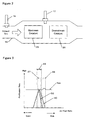
- FIG. 2 shows a structure of the catalyst converter 15.
- Exhaust gas introduced into the exhaust manifold 14 passes through the upstream catalyst 25 and then through the downstream catalyst 26. It is known that it is easier to maintain the purification rate of Nox at an optimal level by air-fuel ratio control based on the output of an O2 sensor provided between the upstream and downstream catalysts, compared with air-fuel ratio control based on the output of an O2 sensor provided downstream of the downstream catalyst. Therefore, in the embodiment of the invention described hereafter, the O2 sensor 17 is provided between the upstream and downstream catalysts. The O2 sensor 17 detects the concentration of oxygen included in the exhaust gas after the passage through the upstream catalyst 25.
- the O2 sensor may be disposed downstream of the downstream catalyst 26. If the catalyst converter 15 is implemented with a single catalyst, the O2 sensor is disposed downstream of the catalyst converter 15.
- FIG. 3 shows purification behavior of the upstream catalyst and the downstream catalyst.
- a window 27 indicates an air-fuel ratio region in which CO, HC and Nox are optimally purified. Since oxygen included in exhaust gas is consumed by the purification in the upstream catalyst 25, the exhaust gas supplied to the downstream catalyst 26 exhibits a reduction atmosphere (i.e., a rich state) as shown by a window 28. In such a reduction atmosphere, Nox is further purified. Thus, the cleaned exhaust gas is discharged.
- adaptive control of the air-fuel ratio causes the output of the O2 sensor 17 to converge to a target value so that the air-fuel ratio is within the window 27.
- a reference number 29 shows an allowable range that defines a limitation of a variable manipulated by the adaptive air-fuel ratio control, which will be described in detail later.
- FIG. 4 shows a block diagram of adaptive air-fuel ratio control in accordance with a first embodiment of the invention.
- the LAF sensor 16 detects an air-fuel ratio KACT of the exhaust gas supplied to the upstream catalyst 25.
- the O2 sensor 17 outputs a voltage Vo2/OUT that indicates the oxygen concentration of the exhaust gas after the purification by the upstream catalyst 25.
- the output Vo2/OUT from the O2 sensor 17 is delivered to a first decimation filter 36.
- the first decimation filter 36 oversamples the output Vo2/OUT of the O2 sensor 17, performs a low-pass filtering process on the oversampled value, and then downsamples the filtered value.
- the output from the first decimation filter 36 is represented by a sample value Vo2_df.
- the sample value Vo2_df is compared with a target value Vo2/TARGET.
- An error Vo2 between the sample value Vo2_df and the target value Vo2/TARGET is supplied to a controller 31.
- An object (i.e., plant) to be controlled by the adaptive air-fuel ratio control is an exhaust system 19 extending from the LAF sensor 16 through the upstream catalyst 25 to the O2 sensor 17.
- the controller 31 determines a target air-fuel ratio error "kcmd" based on the error Vo2.
- the target air-fuel ratio error kcmd is added to a base value FLAF/BASE to determine a target air-fuel ratio KCMD.
- a fuel injection amount is corrected accordance with the target air-fuel ratio KCMD and is supplied to the engine 1. After the fuel injection, the output Vo2/OUT of the O2 sensor 17 is detected again.
- the controller 31 performs a feedback control to determine the target air-fuel ratio KCMD so that the error Vo2 converges to zero.
- the exhaust system 19, which is the controlled object, can be modeled as shown by the equation (1) in which Vo2/OUT is defined as a control output and the output KACT of the LAF sensor is defined as a control input.
- the exhaust system 19 is modeled as a discrete-time system. Such modeling can make the air-fuel ratio control algorithm simple and suitable for computer processing.
- Vo2'(k + 1) a1 ⁇ Vo2'(k) + a2 ⁇ Vo2'(k-1) + b1 ⁇ kact(k - d3)
- the base value FLAF/BASE is set to be a central value for the target air-fuel ratio KCMD.
- the base value FLAF/BASE may be a constant value, or may be established according to the operating state of the engine.
- d3 indicates a dead time in the exhaust system 19.
- the dead time d3 is a time required for the air-fuel ratio detected by the LAF sensor 16 to be reflected in the output of the O2 sensor 17.
- a1", "a2" and “b1" are model parameters, which are generated by an identifier. The identifier will be described later.
- Vo2/OUT(k) Vo2_df(k + d5)
- the dead time d5 is a time required for the O2 sensor output Vo2/OUT to be oversampled, filtered using a low-pass filter and then downsampled.
- a system including the exhaust system 19 and the first decimation filter 36 is determined based on the equations (1) and (2), as shown in the equation (3).
- incorporation of the first decimation filter 36 increases the dead time in the exhaust system.
- an air-fuel ratio manipulating system 18 extending from the ECU 5 through the engine 1 to the LAF sensor 16 can be modeled as shown by the equation (4).
- kact(k) kcmd(k - d2)
- kact(k) KACT(k) - FLAF/BASE
- kcmd(k) KCMD(k) - FLAF/BASE
- the target air-fuel ratio error "kcmd” indicates an error between the target air-fuel ratio KCMD and the base value FLAF/BASE.
- "d2" indicates a dead time in the air-fuel ratio manipulating system 18. The dead time d2 is a time required for the calculated target air-fuel ratio KCMD to be reflected in the output KACT of the LAF sensor 16.
- the air-fuel ratio manipulating system 18 may be included in the object to be controlled by the adaptive air-fuel ratio control.
- the model equation is expressed based on the equations (3) and (4), as shown by the equation (5).
- a dead time "d" is a total dead time in a system comprising the air-fuel ratio manipulating system 18, the exhaust system 19, and the first decimation filter 36. Incorporation of the first decimation filter 36 increases the dead time.
- FIG. 5 shows a more detailed block diagram of the controller 31 shown in Figure 4.
- the controller 31 comprises an identifier 32, an estimator 33, a sliding mode controller 34, and a limiter 35.
- the identifier 32 identifies the model parameters a1, a2 and b1 in the equation (3) so that a modeling error is removed. An identification method performed by the identifier 32 will be described.
- the identifier 32 uses model parameters â1(k-1), â2(k-1) and b and1(k-1) that have been calculated in the previous control cycle to determine a sensor output error Vô2(k) for the current cycle in accordance with the equation (6).
- Vô2(k) â1(k-1) ⁇ Vo2(k-1) + â2(k-1) ⁇ Vo2(k-2) + b 1(k-1) ⁇ kact(k-d1-1)
- the equation (7) indicates an error id/e(k) between the sensor output error Vô2(k) that is calculated in accordance with the equation (6) and a sensor output error Vo2(k) that is actually detected in the current control cycle.
- id/e(k) Vo2(k)-Vô2(k)
- the identifier 32 calculates â1(k), â2(k) and b and1(k) for the current cycle so that the error id/e(k) is minimized.
- a vector ⁇ is defined as shown in the equation (8).
- ⁇ T (k) [â1(k) â2(k) b 1(k)]
- the identifier 32 determines â1(k), â2(k) and b and1(k) in accordance with the equation (9). As shown by the equation (9), â1(k), â2(k) and b and1(k) for the current control cycle are calculated by changing â1(k), â2(k) and b and1(k) calculated in the previous control cycle by an amount proportional to the error id/e(k).
- Past values kcmd(k-d2), kcmd(k-d2-1), ... kcmd(k-d) for the target air-fuel ratio error "kcmd" before the dead time d2 can be replaced with actual air-fuel ratio errors kact(k), kact(k-1), ... kact(k-d+d2) by using the equation (2).
- the equation (11) is derived.
- the sliding mode controller 34 establishes a switching function ⁇ so as to perform the sliding mode control, as shown in the equation (12).
- ⁇ (k) s ⁇ Vo2(k -1) + Vo2(k)
- Vo2(k-1) indicates the sensor output error detected in the previous cycle as described above.
- Vo2(k) indicates the sensor output error detected in the current cycle.
- "s" is a setting parameter of the switching function ⁇ , and is established to satisfy -1 ⁇ s ⁇ 1.
- the equation (13) is shown as a line 41 on a phase plane with Vo2(k-1) being the horizontal axis and Vo2(k) being the vertical axis.
- the line 41 is referred to as a switching line. It is assumed that the initial value of a state variable (Vo2(k-1), Vo2(k)) that is a combination of Vo2(k-1) and Vo2(k) is shown by a point 42.
- the sliding mode control operates to place the state variable shown by the point 42 on the line 41 and then restrain it on the line 41.
- the state variable since the state variable is held on the switching line 41, the state variable can highly stably converge to the origin 0 of the phase plane without being affected by disturbances or the like.
- the sensor output error Vo2 can converge to zero robustly against disturbances and modeling errors.
- the switching function setting parameter "s" is a parameter which can be variably selected. Reduction (convergence) characteristics of the sensor output error Vo2 can be specified by the setting parameter "s.”
- Figure 7 shows one example of response assignment characteristics of the sliding mode control.
- a line 43 shows a case in which the value of the setting parameter is "1.”
- a curve 44 shows a case in which the value of the setting parameter is "0.8.”
- a curve 45 shows a case in which the value of the setting parameter is "0.5.”
- the rate of convergence of the sensor output error Vo2 changes according to the value of the setting parameter "s.” It is seen that the convergence rate becomes faster as the absolute value of "s" becomes smaller.
- Three control inputs are determined to cause the value of the switching function ⁇ to converge to zero. That is, a control input Ueq for confining the state variable on the switching line, a control input Urch for placing the state variable on the switching line, and a control input Uadp for placing the state variable on the switching line while suppressing modeling errors and disturbances.
- the three control inputs Ueq, Urch and Uadp are summed to determine a demand error Usl.
- the demand error Usl is used to calculate the air-fuel ratio error kcmd.
- the reaching law input Urch has a value that depends on the value of the switching function ⁇ .
- the reaching law Urch is determined in accordance with the equation (16).
- the reaching law input Urch has a value proportional to the value of the switching function ⁇ .
- Urch(k) - 1 b1 ⁇ Krch ⁇ (k + d)
- the adaptive law input Uadp has a value that depends on an integrated value of the switching function ⁇ .
- the adaptive law input Uadp is determined in accordance with the equation (17).
- the adaptive law input Uadp has a value proportional to the integrated value of the switching function ⁇ .
- ⁇ T indicates the period of a control cycle.
- the equivalent control input Ueq is determined using an estimated errors Vo2 (k + d) and Vo2 (k + d-1) generated by the estimator 33.
- Ueq(k) - 1 b1 [((a1-1)+s) ⁇ Vo2 (k+d)+(a2-s) ⁇ Vo2 (k+d-1)]
- a switching function ⁇ is determined using the estimated errors generated by the estimator 33, as shown in the equation (19).
- ⁇ s ⁇ Vo2 (k-1) + Vo2 (k)
- the switching function ⁇ is used to determine the reaching law input Urch and the adaptive law input Uadp.
- Urch(k) - 1 b1 ⁇ Krch ⁇ ⁇ (k + d)
- the limiter 35 performs a limiting process for the demand eror Usl to determine the air-fuel ratio error kcmd. More specifically, if the demand error Usl is within an allowable range, the limiter 35 sets the air-fuel ratio error kcmd to the value of the demand error Usl. If the demand error Usl deviates from the allowable range, the limiter 35 sets the air-fuel ratio error kcmd to an upper or lower limit value of the allowable range.
- the allowable range used by the limiter 35 is set to a range whose center is almost located in the window 27 and whose width is wider than that of the window 27.
- the allowable range is actively established in accordance with the demand error Usl, the operating state of the engine and the like. Even when the purification capability of the catalyst converter deviates from the optimal state shown by the window 27, the allowable range has a sufficient width to allow the catalyst converter to quickly return to the optimal state while suppressing variations in combustion conditions that may be caused by variations in the air-fuel ratio. Therefore, the purification rate of the catalyst converter can be kept at high level so that deleterious substances of exhaust gas are reduced.
- the allowable range is variably updated in accordance with the determined demand error Usl.
- the allowable range is extended in accordance with deviation of the demand error Usl from the allowable range.
- the allowable range is reduced.
- the allowable range suitable for the demand error Usl which defines the air-fuel ratio necessary to cause the output of the O2 sensor 17 to converge to the target value, is established.
- the allowable range is established to be narrower as the degree of instability of the output of the O2 sensor 17 becomes higher.
- the allowable range may be established in accordance with the operating state of the engine including an engine start, an idling state, and cancellation of a fuel cut.
- the determined air-fuel ratio error kcmd is added to the base value FLAF/BASE to determine the target air-fuel ratio KCMD.
- the target air-fuel ratio KCMD is given to the exhaust system 19 (that is the object to be controlled), thereby causing the sensor output error Vo2 to converge to zero.
- the base value FLAF/BASE of the air-fuel ratio may be updated in accordance with the adaptive law input Uadp determined by the sliding mode controller 34 after the completion of the limiting process by the limiter 35. More specifically, the base value FLAF/BASE is initialized to the stoichiometric air-fuel ratio. If the adaptive law input Uadp exceeds a predetermined upper limit value, the basee value FLAF/BASE is increased by a predetermined amount. If the adaptive law input Uadp is below a predetermined lower limit value, the base value FLAF/BASE is decreased by a predetermined amount. If the adaptive law input Uadp is between the upper and lower limit values, the base value FLAF/BASE is not updated. The base value FLAF/BASE thus updated is used in the next control cycle. Thus, the base value FLAF/BASE is adjusted to be a central value for the target air-fuel ratio KCMD.
- the allowable range of the demand error Usl is balanced between positive and negative values. It is preferable that the updating process for the base value FLAF/BASE is performed when it is determined that the output Vo2/OUT of the O2 sensor substantially converges to the target value Vo2/TARGET and that the sliding mode control is in a stable state.
- FIG 8 is a block diagram of the first decimation filter 36.
- a first oversampler 51 oversamples the O2 sensor output Vo2/OUT in a shorter cycle "n" than the control cycle "k” that is used for calculating the manipulated variable Usl for manipulating the air-fuel ratio (that is, "k” is the control cycle shown in the above equations).
- the cycle “n” for the oversampling process is, for example, one-fifth of the control cycle "k.”
- the oversampled value Vo2_ov is provided to a first low-pass filter 52.
- the first low-pass filter 52 performs a filtering process on the oversampled value Vo2_ov in accordance with the equation (23) to output Vo2_ovf.
- a1ovf, a2ovf, a3ovf, b0ovf, b1ovf, b2ovf and b3ovf are filtering coefficients that are predetermined with simulation or the like.
- Vo2_ovf(n) a1ovf ⁇ Vo2_ovf(n-1) + a2ovf.Vo2_ovf(n-2)+a3ovf ⁇ Vout_ovf(n-3) +b0ovf ⁇ Vo2_ov(n)+b1ovf ⁇ Vo2_ov(n-1) +b2ovf ⁇ Vo2_ov(n-2)+b3ovf ⁇ Vo2_ov(n-3)
- a first downsampler 53 re-samples the filtered value Vo2_ovf in the control cycle "k" to output a sample value Vo2_df.
- a method for detecting deterioration of the catalyst based on the O2 sensor output in a certain frequency regions has been proposed. It is preferable that the first low-pass filter is designed without invalidating such detection of the catalyst deterioration.
- Figure 9 shows a power spectrum of the O2 sensor output Vo2/OUT (a) when the catalyst is new, (b) when the purification rate of the catalyst is sufficient, and (c) when the purification rate of the catalyst is insufficient.
- the level of the power spectrum of the sensor output Vo2/OUT in the frequency region of 3 through 7 Hz varies, which is indicated by reference number 61.
- Figures 10(a) through 10(c) show a result of filtering the sensor output Vo2/OUT shown in Figures 9(a) through 9(c) with a band-pass filter, respectively.
- the power spectrum of the sensor output Vo2/OUT in the frequency region of 3 through 7 Hz is emphasized by the filter.
- reference number 62 As the catalyst deteriorates, the power spectrum of the sensor output Vo2/OUT in the frequency regions 3 through 7 Hz increases.
- the first low-pass filter 52 is preferably designed not to cut the frequency region of 3 through 7 Hz.
- Figure 11 shows filter characteristics of the first low-pass filter 52.
- Frequency components necessary to detect deterioration of the catalyst exist in a frequency region lower than the line indicated by reference number 64.
- the cut-off frequency is set at a frequency sufficiently higher than the frequency required for detecting deterioration of the catalyst.
- the first low-pass filter 52 does not reduce the accuracy of detecting the catalyst deterioration.
- Figure 12(a) shows one example of the O2 sensor output 65 sampled in the control cycle "k" in accordance with one embodiment of the present invention.
- the O2 sensor whose response is enhanced was used.
- Figure 12 (a) also shows the output Vo2_df 66 from the first decimation filter that has the filter characteristics shown in Figure 11.
- a large variation due to chemical noise appears in the O2 sensor output 65, as shown in the area 67.
- Such large variation due to chemical noise is removed from the output Vo2_df of the first decimation filter.
- the O2 sensor output 65 shown in Figure 12(b) is the same as that shown in Figure 12(a).
- a graph 68 shows Vo2_f obtained by filtering the output of the O2 sensor with a low-pass filter that has filter characteristics shown in Figure 13. As shown in Figure 13, the low-pass filter has a higher cut-off frequency than the frequency required for detecting deterioration of the catalyst. Therefore, the accuracy of detecting deterioration of the catalyst is not reduced. It should be noted that the low-pass filter is applied to the O2 sensor output that has not been oversampled.
- the O2 sensor output 65 shown in Figure 12(c) is the same as that shown in Figure 12(a).
- the graph 70 shows Vo2_f obtained by filtering the output of the O2 sensor with a low-pass filter that has filter characteristics shown in Figure 14.
- the low-pass filter has a lower cut-off frequency than the frequency required for detecting the deterioration of the catalyst, as shown in Figure 14. Therefore, the low-pass filter may reduce the accuracy of detecting deterioration of the catalyst.
- the low-pass filter is applied to the O2 sensor output that has not been oversampled.
- the first decimation filter can remove chemical noise that appears in the sensor output Vo2/OUT without causing a phase delay.
- Figure 15 shows one example of the exhaust gas sensor output Vo2/OUT and the target air-fuel ratio error "kcmd" in accordance with conventional air-fuel ratio control.
- the O2 sensor whose response is enhanced was used.
- high-frequency chemical noise appears in the sensor output, which is caused by the improved response of the O2 sensor.
- reference number 76 such chemical noise causes a large variation in the target air-fuel ratio error kcmd.
- Such a large variation in the target air-fuel ratio error kcmd may reduce the purification rate of the catalyst because the actual air-fuel ratio of the exhaust gas flowing into the catalyst varies according to the target air-fuel ratio error kcmd.
- reference number 81 shows the exhaust gas sensor output V02/OUT
- reference number 82 shows the first decimation filter output V02_df
- reference number 83 shows the target air-fuel ratio error kcmd, in accordance with one embodiment of the present invention.
- the O2 sensor whose response is enhanced was used.
- High-frequency chemical noise appears in the sensor output V02/OUT.
- Such chemical noise is removed as shown in the first decimation filter output Vo2_df.
- the use of the first decimation filter output Vo2_df makes the target air-fuel ratio error kcmd stable.
- Figure 17 shows a block diagram of adaptive air-fuel ratio control in accordance with a second embodiment of the present invention.
- the second embodiment differs from the first embodiment in that the first decimation filter 36 is removed and in that a second decimation filter 37 is provided.
- the output Vo2/OUT of the O2 sensor 17 is compared with a target value Vo2/TARGET.
- An error Vo2 between the sensor output Vo2/OUT and the target value Vo2/TARGET is provided to the controller 31.
- the output KACT of the LAF sensor 16 is delivered to the second decimation filter 37.
- the second decimation filter 37 oversamples the actual air-fuel ratio KACT, filters the oversampled value by a low-pass filtering process, and then downsamples the filtered value to output a sample value KACT_df.
- the sample value KACT_df is compared with the target value FLAF/BASE. An error "kact" between the sample value KACT_df and the target value FLAF/BASE is provided to the controller 31.
- An exhaust system 19, which is an object to be controlled, can be modeled as shown by the equation (24), in which Vo2/OUT is defined as a control output and the output KACT of the LAF sensor is defined as a control input.
- Vo2(k + 1) a1 ⁇ Vo2(k) + a2 ⁇ Vo2(k-1) + b1 ⁇ kact'(k - d3)
- the sensor output error Vo2 indicates an error between the O2 sensor output Vo2/OUT and the target value Vo2/TARGET.
- An actual air-fuel ratio error kact' indicates an error between the LAF sensor output KACT and the base value FLAF/BASE.
- d3 indicates a dead time in the exhaust system 19.
- a1, a2 and b1 are model parameters generated by the above-described identifier.
- KACT(k) KACT_df(k + d6)
- d6 indicates a dead time in the second decimation filter 37.
- the dead time d6 indicates a time required for the LAF sensor output KACT to be oversampled, filtered by the low-pass filtering process, and then dwonsampled.
- a system comprising the exhaust system 19 and the second decimation filter 37 can be obtained from the equations (24) and (25), as shown by the equation (26).
- incorporation of the second decimation filter 37 decreases the dead time in the exhaust system.
- the air-fuel ratio manipulating system 18 extending from the ECU 5 through the engine 1 to the LAF sensor 16 can be modeled as shown by the equation (27).
- kact' (k) kcmd(k - d4)
- kact'(k) KACT(k) - FLAF/BASE
- kcmd(k) KCMD(k) - FLAF/BASE
- the target air-fuel ratio error "kcmd” indicates an error between the target air-fuel ratio KCDM and the base value FLAF/BASE.
- "d4" indicates a dead time in the air-fuel ratio manipulating system 18.
- a system comprising the air-fuel ratio manipulating system 18 and the second decimation filter 37 can be obtained from the equations (25) and (27), as shown by the equation (28).
- incorporation of the second decimation filter 37 increases the dead time in the air-fuel ratio manipulating system.
- the air-fuel ratio manipulating system 18 may be included in the object to be controlled by the adaptive air-fuel ratio control.
- the model equation for the controlled object is expressed based on the equations (26) and (28), as shown by the equation (29).
- the dead time "d" is a total dead time in a system comprising the air-fuel ratio manipulating system 18, the exhaust system 19, and the second decimation filter 37.
- the dead time in the system comprising the air-fuel ratio manipulating system 18, the exhaust system 19, and the second decimation filter 37 is equal to a sum of the dead time d3 in the exhaust system 19 and the dead time d4 in the air-fuel ratio manipulating system 18.
- the dead time d6 in the second decimation filter has no influence on the system.
- the structure of the controller 31 in the second embodiment is the same as that in the first embodiment.
- the dead time d1, d2 and d shown in the above equations regarding the identifier 32, the estimator 33 and the sliding mode controller 34 of the controller 31 are (d3-d6), (d4+d6) and (d3+d4), respectively.
- FIG 18 is a block diagram of the second decimation filter 37.
- a second oversampler 55 oversamples the LAF sensor output KACT in a shorter cycle "n" than the control cycle k that is used for calculating the manipulated variable Usl for the air-fuel ratio control (that is, "k” is the control cycle used in the above equations).
- the cycle “n” for the oversampling process is, for example, one-fifth of the control cycle "k.”
- the oversampled value KACT_ov is provided to a second low-pass filter 56.
- the second low-pass filter 56 filters the oversampled value KACT_ov in accordance with the equation (30) to output KACT_ovf.
- a1ovf', a2ovf', a3ovf', b0ovf', b1ovf', b2ovf' and b3ovf' are filter coefficients predetermined with simulation or the like. Filter characteristics of the second low-pass filter 56 is shown in Figure 19.
- KACT_ovf(n) a1ovf' ⁇ KACT_ovf(n-1) + a2ovf' ⁇ KACT_ovf(n-2) + a3ovf' ⁇ KACT_ovf(n-3) + b0ovf' ⁇ KACT_ov(n)+b1ovf' ⁇ KACT_ov(n-1) + b2ovf' ⁇ KACT_ov(n-2)+b3ovf' ⁇ KACT_ov(n-3)
- a second downsampler 57 re-samples the filtered value KACT_ovf in the control cycle "k" to output a sample value KACT_df.
- reference number 91 shows the actual air-fuel ratio error kact detected by the LAF sensor
- reference number 92 shows the target air-fuel ratio error kcmd calculated based on the error kact in accordance with conventional air-fuel control.
- the LAF sensor whose detection range is expanded was used.
- Reference number 93 shows the model parameter b1 calculated by the identifier 32.
- the model parameter b1 acts to identify correlation between the air-fuel ratio error kact, which is an input of the modeled control system, and the sensor output error Vo2, which is an output of the modeled control system.
- the actual air-fuel ratio error kact takes one of the values of -P2, -P1, 0, +P1 and +P2 due to the low resolution of the LAF sensor.
- an actual air-fuel ratio error that has an intermediate value between 0 and +P1 cannot be detected.
- the actual air-fuel ratio error kact is often detected to be continuously zero as indicated by a flat portion shown in the area 94.
- the identifier determines that there is no correlation between the air-fuel ratio error kact and the sensor output error Vo2. If it is determined that there is no correlation, the identifier decreases the model parameter b1 as shown by reference number 93. Thus, the identification accuracy of the model parameter b1 deteriorates.
- the sliding model control reaches an over-corrected state. This state increases variation in the target air-fuel ratio error kcmd, as indicated by the region 95 of the graph 92, thereby reducing the purification rate of the catalyst.
- reference number 97 shows the actual air-fuel ratio error kact detected by the LAF sensor
- reference number 98 shows the output KACT_df from the second decimation filter 37 in accordance with the second embodiment of the present invention.
- the LAF sensor whose detection range is expanded was used. It is seen that values that cannot be detected by the LAF sensor (that is, values below the resolution limit of the LAF sensor) are estimated by applying the second decimation filter to the actual air-fuel ratio KACT. There is no continuous flat portion in KACT_df. Therefore, the identifier determines that there is correlation between the actual air-fuel ratio error kact and the sensor output error Vo2. The value of the identification parameter b1 becomes stable as shown by a graph 99.
- the second decimation filter compensates the shortage of resolution of the LAF sensor.
- the cycle "n" used for the oversampling process in the second decimation filter 37 may be the same as the cycle used for the oversampling process in the first decimation filter 36.
- the cycle "n" used in the second decimation filter 37 may be different from the cycle used in the first decimation filter 36.
- Figure 22 shows a block diagram of adaptive air-fuel ratio control in accordance with a third embodiment of the present invention.
- the third embodiment both of the first decimation filter 36 and the second decimation filter 37 are provided.
- the output Vo2/OUT of the O2 sensor 17 is delivered to the first decimation filter 36.
- the output Vo2_df from the first decimation filter 36 is compared with the target value Vo2/TARGET.
- An error Vo2 between the sample value Vo2_df and the target value Vo2/TARGET is supplied to the controller 31.
- the output KACT of the LAF sensor 16 is delivered to the second decimation filter 37.
- the output KACT_df from the second decimation filter 37 is compared with the target value FLAF/BASE.
- An error kact between the sample value KACT_df and the target value FLAF/BASE is supplied to the controller 31.
- the exhaust system 19, which is an object to be controlled, can be modeled as shown in the equation (31), in which Vo2/OUT is defined as a control output and the LAF sensor output KACT is defined as a control input.
- Vo2'(k + 1) a1 ⁇ Vo2'(k) + a2 ⁇ Vo2'(k - 1) + b1 ⁇ kact'(k - d3)
- a sensor output error Vo2' indicates an error between the O2 sensor output Vo2/OUT and the target value Vo2/TARGET.
- An actual air-fuel ratio error kact' indicates an error between the LAF sensor output KACT and the base value FLAF/BASE.
- d3 indicates a dead time in the exhaust system 19.
- a1, a2 and b1 are model parameters generated by the above-described identifier.
- Relation between the O2 sensor output Vo2/OUT and the output Vo2_df of the first decimation filter is represented by the above equation (2).
- Relation between the LAF sensor output KACT and the output KACT_df of the second decimation filter is represented by the above equation (25).
- a system comprising the exhaust system 19, and the first and the second decimation filters 36 and 37 can be obtained based on the equations (2), (25) and (31), as shown by the equation (32).
- a dead time d6 in the second decimation filter 37 is equal to a dead time d5 in the first decimation filter 36, a dead time of the exhaust system in which the first and the second decimation filters 36 and 37 are provided is d3. That is, incorporation of the first and the second decimation filters 36 and 37 has no influence on the exhaust system.
- the air-fuel ratio manipulating system 18 extending from the ECU 5 through the engine 1 to the LAF sensor 16 is modeled as shown by the above equation (27).
- a system comprising the air-fuel ratio manipulating system 18, the first and the second decimation filters 36 and 37 is expressed by the above equation (28).
- the dead time in the first decimation filter has no influence on the air-fuel ratio manipulating system 18.
- the air-fuel ratio manipulating system 18 may be included in the object to be controlled by the adaptive air-fuel ratio control.
- the model equation of the object to be controlled is expressed based on the equations (32) and (28), as shown by the equation (33).
- a dead time d is a total dead time in a system comprising the air-fuel ratio manipulating system 18, the exhaust system 19, and the first and second decimation filters 36 and 37.
- the dead time in the system comprising the air-fuel ratio manipulating system 18, the exhaust system 19 and the first and second decimation filters 36 and 37 is equal to a sum of the dead time d3 in the exhaust system 19, the dead time d4 in the air-fuel ratio manipulating system 18, and the dead time d5 in the first decimation filter.
- the dead time d6 in the second decimation filter has no influence on the system.
- the structure of the controller 31 in the third embodiment is the same as that in the first embodiment.
- the dead time d1, d2 and d shown in the above equations regarding the identifier 32, the estimator 33 and the sliding mode controller 34 of the controller 31 are (d3+d5-d6), (d4+d6) and (d3+d4+d5), respectively.
- controller 31 may perform other response assignment control instead of the sliding mode control.
- FIG 23 shows another embodiment of the controller.
- the controller 31 comprises a DSM controller 38 for performing a ⁇ (delta-sigma) modulation algorithm instead of the sliding mode controller.
- FIG 24 shows a block diagram of the DSM controller 38. Since the ⁇ modulation algorithm is conventionally used, detailed description is omitted.
- An amplifier 101 multiplies a sensor output error Vo2 , which is estimated by the estimator 33, by a gain "-G" to output a reference signal "r.”
- a subtractor 102 calculates a difference between the reference signal r and the ⁇ modulation signal u"(k-1) calculated in the previous cycle to output a differential signal ⁇ (k).
- An integrator 103 adds the differential signal ⁇ (k) calculated in the current cycle to the integrated signal ⁇ '(k-1) calculated in the previous cycle to output an integrated signal ⁇ '(k) for the current cycle.
- the sign function 104 determines +/- of the integrated signal ⁇ '(k) to output a signal u"(k).
- An amplifier 105 multiplies the signal u"(k) by a gain "F” to output a ⁇ modulation signal u(k).
- the ⁇ modulation signal u(k) is a signal indicating the target air-fuel ratio error kcmd.
- the target air-fuel ratio KCMD is calculated by adding the base value FLAF/BASE to the ⁇ modulation signal u(k).
- the DSM controller 38 may be configured to perform a ⁇ (delta) modulation algorithm, which does not contain the integrator.
- the DSM controller 38 may also be configured to perform a ⁇ (sigma-delta) modulation algorithm, in which the integrator is followed by the subtractor.
- the controller 31 comprises both of the sliding mode controller 34 and the DSM controller 38.
- the controller 31 can switch between sliding mode control (or another response assignment control) and ⁇ modulation control (or ⁇ modulation control, ⁇ modulation control) in accordance with the operating state of the engine. For example, the air-fuel ratio is controlled by the ⁇ modulation controller when the load of the engine is low, and the air-fuel ratio is controlled by the sliding mode controller when the load of the engine is high.
- FIG. 25 shows a flowchart of the adaptive air-fuel ratio control in accordance with the above third embodiment of the present invention.
- the cycle "n" for the oversampling process in the first decimation filter is the same as the cycle for the oversampling process in the second decimation filter. This routine is performed in cycle "n.”
- step S111 the output Vo2/OUT of the O2 sensor is sampled and then filtered by the low-pass filter, to determine Vo2_ovf.
- step S112 the LAF sensor output KACT is sampled and then filtered by the low-pass filter to determine KACT_ovf.
- the O2 sensor output Vo2/OUT and the LAF sensor output KACT are oversampled. Steps S111 and S112 may be performed in parallel.
- step S113 it is determined whether a counter CPRISM is zero.
- the initial value of the counter CPRISM is "k/n-1.” For example, when “n” is ten milliseconds and "k" is fifty milliseconds, the initial value of the counter CPRISM is "4.”
- the counter is decremented by one in step S114, exiting the routine. If the counter CPRISM is zero when the routine is re-entered, the process proceeds to step S115, in which the counter is reset. Thus, steps S111 and S112 are carried out in cycle "n” while steps S115 through S122 are carried out in cycle "k.”
- step S116 it is determined whether a permission flag is one.
- the permission flag is a flag that is to be set to one when the execution of the air-fuel ratio control is permitted. For example, the execution of the air-fuel ratio control is not permitted when lean operation is being performed in the engine or when operation for retarding the ignition timing is being performed.
- the permission flag is zero, the target air-fuel ratio error kcmd is set to a predetermined value in step S123, and then the process proceeds to step S124.
- Vo2_ovf filtered in step S111 is sampled in cycle “k” to determine Vo2_df.
- KACT_ovf filtered in step S112 is sampled in cycle "k” to determine KACT_df.
- step S118 the calculation process by the identifier is performed to determine the model parameters a1, a2 and b1 as described above.
- step S119 the calculation process by the estimator is performed to determine the estimated value Vo2 as described above.
- step S120 the manipulated variable Usl is calculated as described above.
- Pstb is equivalent to the time-differential of the Lyapunov function ⁇ 2 /2 concerning the switching function ⁇ .
- the state in which the function value Pstb is equal to or less than zero indicates a state in which the value of the switching function ⁇ converges to zero or is converging to zero.
- the state in which the function value Pstb is greater than zero indicates a state in which the value of the switching function ⁇ is leaving zero.
- step S122 the limitation process is performed by the limiter to determine the target air-fuel ratio error kcmd.
- step S124 the base value FLAF/BASE is added to the target air-fuel ratio error kcmd to determine the target air-fuel ratio KCMD. If the base value FLAF/BASE is established as described above, a step for establishing the base value may be performed after step S124.
- the invention may be applied to an engine to be used in a vessel-propelling machine such as an outboard motor in which a crankshaft is disposed in the perpendicular direction.
- a vehicle controller for controlling the air-fuel ratio of an engine comprises a first exhaust gas sensor provided downstream of the catalyst for detecting oxygen concentration of exhaust gas, a first decimation filter connected to the first exhaust gas sensor, and a control unit connected to the first decimation filter.
- the control unit determines a manipulated variable for manipulating the air-fuel ratio.
- the first decimation filter oversamples, low-pass filters and then downsamples the output of the first exhaust gas sensor.
- the first decimation filter can remove chemical noise from the output of the exhaust gas sensor.
- a second decimation filter is connected to a second exhaust gas sensor provided upstream of the catalyst for detecting the air-fuel ratio of the exhaust gas.
- the second decimation filter overasmples, low-pass filters and then downsamples the output of the second exhaust gas sensor.
- the second decimation filter can compensate the shortage of resolution of the air-fuel ratio sensor.
Landscapes
- Engineering & Computer Science (AREA)
- General Physics & Mathematics (AREA)
- Physics & Mathematics (AREA)
- Mechanical Engineering (AREA)
- General Engineering & Computer Science (AREA)
- Automation & Control Theory (AREA)
- Chemical & Material Sciences (AREA)
- Combustion & Propulsion (AREA)
- Medical Informatics (AREA)
- Health & Medical Sciences (AREA)
- Software Systems (AREA)
- Computer Vision & Pattern Recognition (AREA)
- Artificial Intelligence (AREA)
- Evolutionary Computation (AREA)
- Electrical Control Of Air Or Fuel Supplied To Internal-Combustion Engine (AREA)
- Combined Controls Of Internal Combustion Engines (AREA)
- Exhaust Gas After Treatment (AREA)
Applications Claiming Priority (2)
| Application Number | Priority Date | Filing Date | Title |
|---|---|---|---|
| JP2002234045A JP3957180B2 (ja) | 2002-08-09 | 2002-08-09 | デシメーションフィルタを用いた内燃機関の空燃比制御装置 |
| JP2002234045 | 2002-08-09 |
Publications (3)
| Publication Number | Publication Date |
|---|---|
| EP1388659A2 true EP1388659A2 (de) | 2004-02-11 |
| EP1388659A3 EP1388659A3 (de) | 2008-04-23 |
| EP1388659B1 EP1388659B1 (de) | 2011-08-10 |
Family
ID=30437814
Family Applications (1)
| Application Number | Title | Priority Date | Filing Date |
|---|---|---|---|
| EP03013836A Expired - Lifetime EP1388659B1 (de) | 2002-08-09 | 2003-06-18 | Kraftfahrzeugsteuergerät zur Steuerung des Luftkraftstoffverhältnisses |
Country Status (5)
| Country | Link |
|---|---|
| US (1) | US6904355B2 (de) |
| EP (1) | EP1388659B1 (de) |
| JP (1) | JP3957180B2 (de) |
| CN (1) | CN100375831C (de) |
| CA (1) | CA2435594C (de) |
Cited By (5)
| Publication number | Priority date | Publication date | Assignee | Title |
|---|---|---|---|---|
| EP1734243A1 (de) * | 2004-03-24 | 2006-12-20 | Toyota Jidosha Kabushiki Kaisha | Verbrennungsmotorsteuerung für luft/kraftstoff-verhältnis |
| EP2177739A1 (de) * | 2008-10-14 | 2010-04-21 | Honda Motor Co., Ltd. | Steuerungssystem und Verfahren für Verbrennungsmotor |
| EP2184469A3 (de) * | 2008-11-11 | 2010-06-02 | Honda Motor Co., Ltd | Steuerungssystem und Verfahren für Verbrennungsmotor |
| EP1772610A3 (de) * | 2005-10-06 | 2012-10-17 | Hitachi, Ltd. | Vorrichtung und Methode zur Steuerung des Luftverhältnisses einer Brennkraftmaschine |
| FR3013769A1 (fr) * | 2013-11-25 | 2015-05-29 | Peugeot Citroen Automobiles Sa | Procede de mise en œuvre d'un moteur a combustion interne equipe d'une ligne d'echappement pourvu d'une sonde de gaz d'echappement. |
Families Citing this family (20)
| Publication number | Priority date | Publication date | Assignee | Title |
|---|---|---|---|---|
| EP1574695A3 (de) * | 2004-03-12 | 2011-08-31 | Honda Motor Co., Ltd. | Vorrichtung zur Steuerung einer Anlage unter Verwendung eines Delta-Sigma-Modulation-Algorithmus |
| US7269993B2 (en) * | 2004-06-29 | 2007-09-18 | Honda Motor Co., Ltd. | Gas detecting apparatus, gas detecting method and fuel cell vehicle |
| WO2006072996A1 (ja) | 2005-01-07 | 2006-07-13 | Fujitsu Limited | ノード設定装置、ネットワークシステム、ノード設定方法およびノード設定プログラム |
| JP4627205B2 (ja) | 2005-03-28 | 2011-02-09 | 富士通株式会社 | リングネットワークシステムおよび障害復旧方法 |
| JP4376202B2 (ja) * | 2005-04-07 | 2009-12-02 | 本田技研工業株式会社 | 制御装置 |
| JP4631517B2 (ja) * | 2005-04-13 | 2011-02-16 | トヨタ自動車株式会社 | 酸素センサ及び空燃比制御システム |
| US7538662B2 (en) * | 2005-10-04 | 2009-05-26 | Innovate! Technology, Inc. | Programmable vehicle gauge apparatus, system, and method |
| JP4380625B2 (ja) * | 2005-11-24 | 2009-12-09 | トヨタ自動車株式会社 | 内燃機関の空燃比制御装置 |
| DE112007000998B4 (de) * | 2006-04-24 | 2012-02-09 | Gm Global Technology Operations Llc (N.D.Ges.D. Staates Delaware) | Luftdurchsatzschätzverfahren und -vorrichtung für einen Verbrennungsmotor |
| US7805236B2 (en) * | 2008-01-29 | 2010-09-28 | Stephen Mullen | Apparatus and method for adjusting the performance of an internal combustion engine |
| US7900615B2 (en) * | 2008-10-01 | 2011-03-08 | Gm Global Technology Operations, Inc. | Air-fuel imbalance detection based on zero-phase filtering |
| JP5018902B2 (ja) * | 2010-01-18 | 2012-09-05 | トヨタ自動車株式会社 | 内燃機関装置および内燃機関の制御方法並びに車両 |
| DE102010030868B4 (de) * | 2010-07-02 | 2022-11-10 | Robert Bosch Gmbh | Verfahren zur Diagnose und/oder zur Anpassung von mindestens einem System einer Vorrichtung |
| US10563606B2 (en) * | 2012-03-01 | 2020-02-18 | Ford Global Technologies, Llc | Post catalyst dynamic scheduling and control |
| JP5902727B2 (ja) * | 2014-01-23 | 2016-04-13 | 本田技研工業株式会社 | 内燃機関の排気浄化システム |
| US9874167B2 (en) | 2016-06-08 | 2018-01-23 | GM Global Technology Operations LLC | Control systems and methods for air fuel imbalance and cylinder deactivation |
| US10544746B2 (en) | 2018-06-29 | 2020-01-28 | Fca Us Llc | Pre-turbine wide-range oxygen sensor lambda control during scavenging |
| US11703007B2 (en) * | 2019-04-26 | 2023-07-18 | Nissan Motor Co., Ltd. | Control method of engine system, and engine system |
| CN112664342B (zh) * | 2020-12-29 | 2022-09-13 | 东风汽车集团有限公司 | 一种三元催化剂控制方法及系统 |
| CN115045770B (zh) * | 2022-08-16 | 2022-11-18 | 中国科学院数学与系统科学研究院 | 一种基于二值氧传感器的空燃比控制系统的量化滤波方法 |
Citations (2)
| Publication number | Priority date | Publication date | Assignee | Title |
|---|---|---|---|---|
| US5450083A (en) | 1994-03-09 | 1995-09-12 | Analog Devices, Inc. | Two-stage decimation filter |
| EP0800125A1 (de) | 1996-04-05 | 1997-10-08 | Honda Giken Kogyo Kabushiki Kaisha | Verfahren zur gleitenden Moderegelung |
Family Cites Families (12)
| Publication number | Priority date | Publication date | Assignee | Title |
|---|---|---|---|---|
| US5083427A (en) * | 1990-02-12 | 1992-01-28 | Ford Motor Company | Apparatus and method to reduce automotive emissions using filter catalyst interactive with uego |
| DE69333483T2 (de) * | 1992-07-03 | 2004-08-12 | Honda Giken Kogyo K.K. | Kraftstoffmesssteuersystem und Zylinderluftflussschätzungsmethode im Verbrennungsmotor |
| WO1995008220A1 (en) * | 1993-09-13 | 1995-03-23 | Analog Devices, Inc. | Analog to digital conversion using nonuniform sample rates |
| JP3422393B2 (ja) * | 1995-02-24 | 2003-06-30 | 本田技研工業株式会社 | 内燃機関の空燃比制御装置 |
| US5774822A (en) * | 1995-02-25 | 1998-06-30 | Honda Giken Kogyo Kabushiki Kaisha | Fuel metering control system for internal combustion engine |
| JP3498455B2 (ja) * | 1995-12-08 | 2004-02-16 | 日産自動車株式会社 | スロットルバルブの位置決め制御装置 |
| JP3592519B2 (ja) | 1997-09-16 | 2004-11-24 | 本田技研工業株式会社 | 内燃機関の排気系の空燃比制御装置及びプラントの制御装置 |
| US6449944B1 (en) * | 1998-07-17 | 2002-09-17 | Honda Giken Kogyo Kabushiki Kaisha | Method of judging deterioration of emission gas control catalyst device |
| JP3621839B2 (ja) * | 1998-12-17 | 2005-02-16 | 本田技研工業株式会社 | プラントの制御装置 |
| JP4265704B2 (ja) * | 1999-04-14 | 2009-05-20 | 本田技研工業株式会社 | 内燃機関の空燃比制御装置及びプラントの制御装置 |
| JP3782269B2 (ja) * | 1999-11-12 | 2006-06-07 | 本田技研工業株式会社 | 内燃機関の空燃比制御装置 |
| JP4312325B2 (ja) * | 1999-12-28 | 2009-08-12 | 本田技研工業株式会社 | 排ガス浄化用触媒装置の劣化状態評価方法 |
-
2002
- 2002-08-09 JP JP2002234045A patent/JP3957180B2/ja not_active Expired - Fee Related
-
2003
- 2003-06-18 EP EP03013836A patent/EP1388659B1/de not_active Expired - Lifetime
- 2003-07-18 CA CA002435594A patent/CA2435594C/en not_active Expired - Fee Related
- 2003-08-05 CN CNB031526764A patent/CN100375831C/zh not_active Expired - Fee Related
- 2003-08-07 US US10/635,464 patent/US6904355B2/en not_active Expired - Lifetime
Patent Citations (2)
| Publication number | Priority date | Publication date | Assignee | Title |
|---|---|---|---|---|
| US5450083A (en) | 1994-03-09 | 1995-09-12 | Analog Devices, Inc. | Two-stage decimation filter |
| EP0800125A1 (de) | 1996-04-05 | 1997-10-08 | Honda Giken Kogyo Kabushiki Kaisha | Verfahren zur gleitenden Moderegelung |
Cited By (8)
| Publication number | Priority date | Publication date | Assignee | Title |
|---|---|---|---|---|
| EP1734243A1 (de) * | 2004-03-24 | 2006-12-20 | Toyota Jidosha Kabushiki Kaisha | Verbrennungsmotorsteuerung für luft/kraftstoff-verhältnis |
| EP1734243A4 (de) * | 2004-03-24 | 2013-06-26 | Toyota Motor Co Ltd | Verbrennungsmotorsteuerung für luft/kraftstoff-verhältnis |
| EP1772610A3 (de) * | 2005-10-06 | 2012-10-17 | Hitachi, Ltd. | Vorrichtung und Methode zur Steuerung des Luftverhältnisses einer Brennkraftmaschine |
| EP2177739A1 (de) * | 2008-10-14 | 2010-04-21 | Honda Motor Co., Ltd. | Steuerungssystem und Verfahren für Verbrennungsmotor |
| EP2302187A1 (de) * | 2008-10-14 | 2011-03-30 | Honda Motor Co., Ltd. | Steuerungssystem und Verfahren für Verbrennungsmotor |
| US8005605B2 (en) | 2008-10-14 | 2011-08-23 | Honda Motor Co., Ltd. | Control system and method for internal combustion engine and engine control unit |
| EP2184469A3 (de) * | 2008-11-11 | 2010-06-02 | Honda Motor Co., Ltd | Steuerungssystem und Verfahren für Verbrennungsmotor |
| FR3013769A1 (fr) * | 2013-11-25 | 2015-05-29 | Peugeot Citroen Automobiles Sa | Procede de mise en œuvre d'un moteur a combustion interne equipe d'une ligne d'echappement pourvu d'une sonde de gaz d'echappement. |
Also Published As
| Publication number | Publication date |
|---|---|
| CA2435594C (en) | 2010-01-12 |
| CN100375831C (zh) | 2008-03-19 |
| EP1388659B1 (de) | 2011-08-10 |
| JP3957180B2 (ja) | 2007-08-15 |
| US6904355B2 (en) | 2005-06-07 |
| CN1480634A (zh) | 2004-03-10 |
| JP2004076593A (ja) | 2004-03-11 |
| EP1388659A3 (de) | 2008-04-23 |
| US20040030484A1 (en) | 2004-02-12 |
| CA2435594A1 (en) | 2004-02-09 |
Similar Documents
| Publication | Publication Date | Title |
|---|---|---|
| EP1388659B1 (de) | Kraftfahrzeugsteuergerät zur Steuerung des Luftkraftstoffverhältnisses | |
| US7430854B2 (en) | Air fuel ratio controller for internal combustion engine for stopping calculation of model parameters when engine is in lean operation | |
| JP3973922B2 (ja) | 制御装置 | |
| US6195988B1 (en) | Air-fuel ratio control system for internal combustion engine | |
| JP3592519B2 (ja) | 内燃機関の排気系の空燃比制御装置及びプラントの制御装置 | |
| EP0908801B1 (de) | Anlagesteuersystem | |
| US6188953B1 (en) | Plant control system | |
| EP0908800A2 (de) | Anlagesteuersystem | |
| US6978203B2 (en) | Controller for controlling element temperature of exhaust gas sensor | |
| US6868326B2 (en) | Control apparatus, control method, control unit, and engine control unit | |
| US6935155B2 (en) | Apparatus for detecting failure of exhaust gas sensor utilizing element temperature | |
| EP1091110A2 (de) | Luft-Kraftstoffverhältnissteuerapparat für multizylindrigen Verbrennungsmotor | |
| JP3304844B2 (ja) | プラントの制御装置 | |
| EP1331384B1 (de) | Luft-Kraftstoffverhältnis-Regelung unter Benutzung eines virtuellen Abgassensors | |
| JP2002349325A (ja) | 内燃機関の空燃比制御装置 | |
| JP3976639B2 (ja) | 内燃機関の空燃比制御装置 | |
| JP3808816B2 (ja) | 空燃比の基準値の更新許可を判断する内燃機関の空燃比制御装置 | |
| JP2003201894A (ja) | 内燃機関の空燃比制御装置 |
Legal Events
| Date | Code | Title | Description |
|---|---|---|---|
| PUAI | Public reference made under article 153(3) epc to a published international application that has entered the european phase |
Free format text: ORIGINAL CODE: 0009012 |
|
| AK | Designated contracting states |
Kind code of ref document: A2 Designated state(s): AT BE BG CH CY CZ DE DK EE ES FI FR GB GR HU IE IT LI LU MC NL PT RO SE SI SK TR |
|
| AX | Request for extension of the european patent |
Extension state: AL LT LV MK |
|
| PUAL | Search report despatched |
Free format text: ORIGINAL CODE: 0009013 |
|
| AK | Designated contracting states |
Kind code of ref document: A3 Designated state(s): AT BE BG CH CY CZ DE DK EE ES FI FR GB GR HU IE IT LI LU MC NL PT RO SE SI SK TR |
|
| AX | Request for extension of the european patent |
Extension state: AL LT LV MK |
|
| 17P | Request for examination filed |
Effective date: 20080610 |
|
| 17Q | First examination report despatched |
Effective date: 20080708 |
|
| AKX | Designation fees paid |
Designated state(s): DE FR GB IT |
|
| GRAP | Despatch of communication of intention to grant a patent |
Free format text: ORIGINAL CODE: EPIDOSNIGR1 |
|
| GRAS | Grant fee paid |
Free format text: ORIGINAL CODE: EPIDOSNIGR3 |
|
| GRAA | (expected) grant |
Free format text: ORIGINAL CODE: 0009210 |
|
| AK | Designated contracting states |
Kind code of ref document: B1 Designated state(s): DE FR GB IT |
|
| REG | Reference to a national code |
Ref country code: GB Ref legal event code: FG4D |
|
| REG | Reference to a national code |
Ref country code: DE Ref legal event code: R096 Ref document number: 60337948 Country of ref document: DE Effective date: 20111013 |
|
| PG25 | Lapsed in a contracting state [announced via postgrant information from national office to epo] |
Ref country code: IT Free format text: LAPSE BECAUSE OF FAILURE TO SUBMIT A TRANSLATION OF THE DESCRIPTION OR TO PAY THE FEE WITHIN THE PRESCRIBED TIME-LIMIT Effective date: 20110810 |
|
| PLBE | No opposition filed within time limit |
Free format text: ORIGINAL CODE: 0009261 |
|
| STAA | Information on the status of an ep patent application or granted ep patent |
Free format text: STATUS: NO OPPOSITION FILED WITHIN TIME LIMIT |
|
| 26N | No opposition filed |
Effective date: 20120511 |
|
| PGFP | Annual fee paid to national office [announced via postgrant information from national office to epo] |
Ref country code: GB Payment date: 20120613 Year of fee payment: 10 Ref country code: FR Payment date: 20120619 Year of fee payment: 10 |
|
| REG | Reference to a national code |
Ref country code: DE Ref legal event code: R097 Ref document number: 60337948 Country of ref document: DE Effective date: 20120511 |
|
| REG | Reference to a national code |
Ref country code: DE Ref legal event code: R084 Ref document number: 60337948 Country of ref document: DE Effective date: 20130211 |
|
| GBPC | Gb: european patent ceased through non-payment of renewal fee |
Effective date: 20130618 |
|
| REG | Reference to a national code |
Ref country code: FR Ref legal event code: ST Effective date: 20140228 |
|
| PG25 | Lapsed in a contracting state [announced via postgrant information from national office to epo] |
Ref country code: GB Free format text: LAPSE BECAUSE OF NON-PAYMENT OF DUE FEES Effective date: 20130618 |
|
| PG25 | Lapsed in a contracting state [announced via postgrant information from national office to epo] |
Ref country code: FR Free format text: LAPSE BECAUSE OF NON-PAYMENT OF DUE FEES Effective date: 20130701 |
|
| PGFP | Annual fee paid to national office [announced via postgrant information from national office to epo] |
Ref country code: DE Payment date: 20190604 Year of fee payment: 17 |
|
| REG | Reference to a national code |
Ref country code: DE Ref legal event code: R119 Ref document number: 60337948 Country of ref document: DE |
|
| PG25 | Lapsed in a contracting state [announced via postgrant information from national office to epo] |
Ref country code: DE Free format text: LAPSE BECAUSE OF NON-PAYMENT OF DUE FEES Effective date: 20210101 |