EP1388446A2 - Inner liner for vehicle body - Google Patents
Inner liner for vehicle body Download PDFInfo
- Publication number
- EP1388446A2 EP1388446A2 EP03016743A EP03016743A EP1388446A2 EP 1388446 A2 EP1388446 A2 EP 1388446A2 EP 03016743 A EP03016743 A EP 03016743A EP 03016743 A EP03016743 A EP 03016743A EP 1388446 A2 EP1388446 A2 EP 1388446A2
- Authority
- EP
- European Patent Office
- Prior art keywords
- inner shell
- flap
- use position
- shell
- bearing
- Prior art date
- Legal status (The legal status is an assumption and is not a legal conclusion. Google has not performed a legal analysis and makes no representation as to the accuracy of the status listed.)
- Withdrawn
Links
Images


Classifications
-
- B—PERFORMING OPERATIONS; TRANSPORTING
- B60—VEHICLES IN GENERAL
- B60R—VEHICLES, VEHICLE FITTINGS, OR VEHICLE PARTS, NOT OTHERWISE PROVIDED FOR
- B60R13/00—Elements for body-finishing, identifying, or decorating; Arrangements or adaptations for advertising purposes
- B60R13/02—Internal Trim mouldings ; Internal Ledges; Wall liners for passenger compartments; Roof liners
- B60R13/0212—Roof or head liners
-
- B—PERFORMING OPERATIONS; TRANSPORTING
- B60—VEHICLES IN GENERAL
- B60R—VEHICLES, VEHICLE FITTINGS, OR VEHICLE PARTS, NOT OTHERWISE PROVIDED FOR
- B60R13/00—Elements for body-finishing, identifying, or decorating; Arrangements or adaptations for advertising purposes
- B60R13/02—Internal Trim mouldings ; Internal Ledges; Wall liners for passenger compartments; Roof liners
- B60R13/0275—Internal Trim mouldings ; Internal Ledges; Wall liners for passenger compartments; Roof liners comprising removable or hinged parts
Definitions
- the present invention relates to an inner shell or an interior trim part for vehicle bodies accordingly the preamble of claim 1.
- the invention relates to a vehicle roof module, the inner shell assigned at least one flap serving as a sun visor is.
- Such prefabricated vehicle roofs ready for installation are finished separately from the vehicle body and only on the assembly line in the automobile factory with the vehicle body united. Especially because of the considerable shortening Such vehicle roof modules gain the assembly time on the assembly line increasingly important in mass production.
- a vehicle roof module whose inner shell at least one as a sun visor serving flap is assigned are according to the invention trained inner shells basically for all surface areas of vehicle bodies, including hoods, doors and flaps / lids, and regardless of whether the each area now around a fixed body component or a module part, suitable, on the inside a flap-like element is provided, which is optional can be opened or closed, for example, to access Allow functional elements on the respective part where fasteners, locks, drive elements, such as electric motors, gears or cables for window regulators, electrical components, e.g.
- Lamps, antennas or loudspeakers, or the like functional elements can act.
- flaps optionally close cavities, such as the Serve inclusion of sunglasses, garage door openers, etc. insofar is a vehicle roof module with a sun visor arrangement to be precise about the place of application described or case of the invention, but without restrictive meaning.
- the invention has for its object an inner shell for vehicle bodies, the at least one optional movable between a non-use position and a use position Flap is assigned to develop such that the Flap arrangement is designed to save space.
- the valve is not in its non-use position or at most only very slightly over the inner shell in Thickness direction before, so that they are particularly in their use as a sun visor on a vehicle roof or module of the driver is not additionally restricted and furthermore the Vehicle interior with a view to maximum headroom can be optimized for the driver or passengers. Also is a visually appealing by the measures according to the invention outer appearance of the inner shell achieved because the flaps to be provided on the inner shell for functional reasons in their non-use position for the vehicle occupants visible surface of the inner shell not in terms of design undesirably "fissured".
- the flap as Part of the inner shell is formed, the overall structure is simplified, being a part that is used to form the interior trim of the vehicle is to be provided anyway, namely the inner shell, at least one additional function is assigned. Not least in terms of the total weight of the corresponding Body part is the solution according to the invention as advantageous to evaluate: The fact that the flap as part of the Inner shell is designed for the flap as such no additional part that increases the total weight, such as conventional sun visor arrangements.
- the flap is useful connected at one edge to the inner shell via a hinge. If the hinge lies in the direction of travel of the vehicle in front of the flap serving as a sun visor, as in the claim 3 indicated, this has the advantage that if the Driver opens the flap for shading the vehicle interior swings down when not in use, the flap Blinking angle continuously narrowed.
- the hinge in Driving direction of the vehicle seen behind the as a sun visor serving flap it occurs during the pivoting movement of the Flap from their non-use position to their use position at short notice in addition to restricting headroom also an extreme narrowing of the viewing angle during which it is for it is difficult for the driver to observe the traffic situation, which can lead to dangerous situations.
- Claim 4 also sees a manufacturing technology here Favorable embodiment that the flap in one piece is formed with the inner shell, the hinge in advantageously simple by a reduced in thickness Section of the inner shell is formed.
- the flap points to the Hinge edge adjoining side edges that in the non-use position the flap from adjacent edges of the inner shell are separated by parting lines, which are advantageous just get trained. It is basically possible that the joints in a central area of the inner shell, i.e. formed from the edge of the inner shell in its surface become. Technically simpler and at least in this respect however, it is preferred if, as in claim 6 specified, the parting lines starting from one end of the Inner shell, i.e. from its edge to the inside of the inner shell extend.
- a guide device provided for the pivoting movement of the flap, which is complementary interlocking circular arc sections which provide guidance has, which with respect to a pivot axis of Flap are centered.
- a management facility on the one hand ensures a good feeling of activity when the Flap is swung out of its non-use position because the flap is not only held over the hinge.
- the Flap also in intermediate positions between their non-use position and let go of their position of use without the flap due to its own weight from this intermediate position moved away.
- a circular arc section through a foamed bearing shell formed during the other arc section through one of the flap adjacent the inner shell is foamed bearing shell, wherein one of the bearing shells has an arcuate slot, which has an arcuate end of the other bearing shell slidably accommodates.
- a holding device for releasably fixing the flap in its non-use position and / or their position of use may be provided with one assigned to the non-use position or use position, with respect to a non-movable part of the inner shell Locking groove, into the locking lug assigned to the flap can be snapped into place.
- Such a holding device can each According to requirements for an additional fixation the flap in their respective end position, so that about a relatively long flap when the motor vehicle is in motion tends to vibrate rather than accidentally can move away from their respective end position.
- the locking grooves on circular arc-shaped slot of one bearing shell, while the latch at the circular end of the other Bearing shell is formed.
- the flap is by means of biased at least one spring element into the non-use position, that instead of or in addition to that mentioned above Guide or holding device may be provided can.
- the spring element is on the one hand a good feeling of operation beneficial when swinging the flap down or out, because the spring element for a defined actuation resistance provides.
- When swiveling the Flap supports the spring element in an advantageous manner Operator during the swivel movement.
- that ensures Spring element for a defined end position of the flap in the Non-use position, from which the flap is due to the spring preload also not automatically or in unintentional Way can move away.
- advantageous Further spring devices are two spring elements provided, each on one of the flexible side wall sections attack, the spring elements the side wall sections and thus the flap indirectly in the non-use position Pretension.
- the spring elements here in advantageously also for the flexible side wall sections assume a defined end position when the Flap is in its non-use position.
- the spring elements pull when the flap moves the flexible from the use position to the non-use position.
- Sidewall sections from the parting lines between the side edges the flap and the adjacent edges of the inner shell away so that the side wall sections are not in the parting lines can be damaged or there the pivoting movement of the Can hinder flap.
- Claim 17 provides that in one piece with the flap a recessed grip is formed on which the operator can attack can to the flap from the non-use position in the Use position or vice versa to move. As a result of the one-piece There is no need to form the recessed grip with the flap here other parts such as handle scales and the associated additional assembly steps.
- the figures show one molded from a foam plastic Inner shell 10 for a vehicle roof module 12 as an example for a module part on vehicle bodies, the inner shell 10 at least one, two in the illustrated embodiment Flaps 14 are assigned, which can be selected from one of the 1, 3, 4 and 6 non-use position shown in a in the Fig. 2 and 5 use position shown and vice versa can be moved.
- the flaps 14 are used in the illustrated embodiment as sun visors, but instead or in addition also access to a functional element (not shown) and / or allow a cavity 16 of the vehicle roof module 12. It is essential that the flaps 14 as part of the inner shell 10 are formed and in their non-use position in essentially flush with the flap Complete 14 adjacent areas of the inner shell 10, such as 1, 4 and 6 in particular.
- the vehicle roof module 12 also includes the inner shell 10 with the flaps 14 etc. a centrally located Interior light 18, which is embedded in the inner shell 10 and is essentially flush with it, as well as handles 20 arranged on each of its two sides, which are in easily accessible locations for vehicle occupants are located.
- the vehicle roof module 12 is in the Figures in an already mounted on the body frame of the vehicle Condition shown, the windshield of the vehicle 22, the A-pillar 24 and a side window 26 in the 1 to 3 can be seen.
- a front cross member of the body frame is designated 28 in Figs. 4 to 6.
- the inner shell 10 of the vehicle roof module 12 is made a foam plastic molded in the embodiment shown is foamed onto a rigid roof skin 30.
- the rigid roof skin 30 consists of a deep-drawn metal sheet, for example aluminum sheet, or can be formed from a vacuum-formed plastic film his. 4 and 5 also show that the inner shell 10 in Area of the intended for resting on the body frame Outer edges of the vehicle roof module 12 in two layers 32, 34 is divided, of which the upper layer 32 on the body frame is applied, while the lower layer 34 in one piece is formed with the flaps 14, as described in more detail will also be used to cover the body frame serves. It was mentioned at the beginning that the Inner shell 10 basically also separately from the respective body part produced and then subsequently with the help of suitable Fasteners on the respective body part if necessary can also be detachably attached.
- Suitable materials for the inner shell 10 are rigid foam plastics based on PUR, which is protected by the plastic in front of the Foaming incorporated fiber materials, for example glass fiber sections, can be armored. But also in the foam form inlaid fabrics, knitted fabrics, fleeces and the like are used as reinforcement suitable.
- the upper layer 32 according to FIGS. 4 and 5 up to an edge fold 36 of the roof skin 30 is sufficient sandwich-like composite roof module with high dimensional stability and Strength. All contours of the inner shell 10 including the lower layer 34 and its profiles are made by appropriate Shaping the foam mold (not shown) is formed.
- the inner surface of the inner shell facing the vehicle interior 10 is in the illustrated embodiment for training a headliner coated with a reference material 38, which is flexible enough to fit the inside surface of the Adapt inner shell 10.
- a reference material 38 which is flexible enough to fit the inside surface of the Adapt inner shell 10.
- the reference material 38 can be made of a textile fabric, Leather, an imitation leather or suede or a decorative plastic film, depending on the respective Design requirements.
- FIGS. 4 and 5 In the area of the support on the body frame is the upper one Layer 32 of the inner shell 10 with circumferentially molded receiving grooves 40 in which the vehicle roof module 12 against the body frame, in FIGS. 4 and 5 only schematically shown adhesive beads 42 added are, which also the attachment of the vehicle roof module 12 on Body frames serve.
- adhesive beads 42 added are, which also the attachment of the vehicle roof module 12 on Body frames serve.
- Mounting screws 44 which are assigned mounting holes in the front transverse part 28 of the body frame of reach through at the bottom and are screwed into threaded holes, the metal profile foamed in one of the upper layer 32 46 are formed. From Fig. 5 it can be seen that the mounting screws 44 easily accessible from the vehicle interior are when the flaps 14 are in their position of use.
- an elastomeric sealing profile 48 which has a projecting outer lip 50 sealingly abuts the outer surface of the roof skin 30 while sealing a projecting inner lip 52 of the sealing profile 48 the edge fold 36 of the roof skin 30 rests.
- an outwardly projecting Flange of the front cross member 28 of the body frame takes over another bead of adhesive 54 the attachment and sealing the windshield 22 on or opposite the vehicle body.
- Parting lines 66 Cut. Also starting from the free end of the inner shell 10 or lower layer 34 extending to the hinge 58 Parting lines 66 can easily be made by suitable Form protrusions in the foam mold (not shown). The same applies to a one-piece with the flap 14 Grip recess 68, which is at the free end of each Flap 14 is located.
- FIGS. 2 and 6 there are between the side edges 62 of the flap 14 and the edges adjacent to it 64 of the lower layer 34 of the inner shell 10 flexible side wall sections 70 provided by moving the flap 14th from their non-use position to their use position a substantially triangular sheet according to FIG. 2 can be stretched out for additional shading of the vehicle interior or a side view of the cavity 16 prevented.
- the side wall portions 70 through the on the surface of the inner shell 10 'facing the vehicle interior provided reference material 38 is formed. It would be conceivable here but also an embodiment in which the side wall sections 70 formed by additional fabric or film sections that are on the side edges 62 of the respective flap 14 and the opposite edges 64 of the lower ones Layer 34 are suitably attached, such as by means of an adhesive.
- each flap 14 is on the vehicle interior opposite side of each flap 14 in the vicinity each flap side edge 62 a spring element 72 is provided, so that each flap 14 two spring elements 72 are assigned.
- the Spring elements 72 each engage one of the side wall sections 70, whereby the spring elements 72 the side wall sections 70 and thus also the respective flap 14 in the Pretension when not in use. More specifically, it is in the exemplary embodiment shown with the spring elements 72 around simply angled wire sections, each a longer one first leg 74 and a shorter second leg 76 exhibit.
- the first leg 74 of the spring element 72 is in accordance with 3 and 6 substantially in the center of the respective side wall section 70 by means of at least one fabric loop 78 fixed, which wraps around the first leg 74 and on suitable Way, for example by gluing and / or sewing on the respective side wall section 70 is attached.
- the free end of the second Leg 76 of the spring element 72 is according to FIG. 4 and 5 rotatably mounted in a bearing block 80, which is in one piece with a bearing shell described in more detail below 82 is formed, which is adjacent to the flap 14 on the on the lower layer facing away from the vehicle interior 34 of the inner shell 10 is foamed.
- the spring elements 72 when pivoting the flap 14 from their non-use position in their Use position over the spanning side wall sections 70, which in this case on the first legs 74 of the spring elements 72 pull over the fabric loops 78, based on the respective Flap 14 are spring open to the outside.
- the flap 14 is off pivoted back into its non-use position, thus the spring elements spring back 72 the pivoting movement in which the first leg 74 over the fabric loops 78 on the side wall sections 70 and thus pull the flap 14 with the side wall portions 70 also from the parting lines 66 in relation to the respective flap 14 be pulled away inside.
- the side wall sections 70 and the spring elements 72 then lie immediately above the flap 14, as Fig. 6 shows.
- the hinge 58 and those aligned with each other Axes of rotation of the second legs 76 of the spring elements 72 in each assigned bracket 80 is not on a common Axis.
- an in 4 and 5 shown guide device for the pivoting movement the respective flap 14 is provided, which is complementary interlocking, causing the flap 14 to be guided
- Has circular arc sections which with respect to the pivot axis the flap 14 are arranged centered. More specifically is a bearing shell on both transverse sides of the respective flap 14 84 the hinge 58 adjacent to that of the vehicle interior opposite side of the flap 14 foamed on the flap 14, with an arcuate shape from each bearing shell 84 End 86 stretched out, each one of the mentioned Forms circular arc sections.
- the other sections of the arc are formed by arcuate slots 88, the in the respective flap 14 adjacent to the lower layer 34 of the inner shell 10 foamed bearing shells 82 are provided.
- 4 and 5 illustrate are the arcuate ends 86 of the flap side Bearing shells 84 are displaceable and essentially free of radial play in the arcuate slots 88 of the inner shell Bearing shells 82 added.
- the preferably made of a suitable plastic Bearing shells 82, 84 also form a holding device for releasable fixation of the respective flap 14 in its non-use position or their position of use, as described in the end shall be.
- This holding device points to both The transverse sides of the corresponding flap 14 each have two locking grooves 90, 92 on, of which a locking groove 90 of the non-use position the flap 14 (Fig. 4) is assigned while the other Locking groove 92 assigned to the position of use of the flap 14 (FIG. 5) is. 4 and 5 also show, the locking grooves 90, 92 suitably angularly spaced on a circular arc Slot 88 of the respective bearing shell 82 is formed, i.e.
- Locking grooves 90, 92 are in the illustrated embodiment with respect of the non-movable part of the inner shell 10 stationary.
- the holding device on both transverse sides of the corresponding flap 14 also one in the locking grooves 90, 92 on the arcuate slot 88 of the respective bearing shell 82 snap-in latch 94, the end of the circular arc End 86 of the corresponding bearing shell 84 formed, i.e. the is assigned to each flap 14.
- each flap 14 allows angular movement the flap 14 in the flap plane as well as translational Height movements of the flap 14 substantially prevented.
- translatory transverse movements of the flap 14 are essentially prevented by the hinge 58.
- the holding device described ensures defined end positions the respective flap 14 in its non-use position or their position of use, the holding device the flap 14 in their position of use also against the force of the spring elements 72 holds.
- the flap is formed as part of the inner shell and closes in their non-use position essentially flush with the surface the areas of the inner shell adjacent to the flap. in the The result is a very space-saving design of the flap arrangement achieved.
Landscapes
- Engineering & Computer Science (AREA)
- Mechanical Engineering (AREA)
- Vehicle Interior And Exterior Ornaments, Soundproofing, And Insulation (AREA)
- Laminated Bodies (AREA)
- Body Structure For Vehicles (AREA)
Abstract
Description
Die vorliegende Erfindung bezieht sich auf eine Innenschale bzw. ein Innenverkleidungsteil für Fahrzeugkarosserien entsprechend dem Oberbegriff des Patentanspruchs 1. Insbesondere bezieht sich die Erfindung auf ein Fahrzeugdachmodul, dessen Innenschale wenigstens eine als Sonnenblende dienende Klappe zugeordnet ist.The present invention relates to an inner shell or an interior trim part for vehicle bodies accordingly the preamble of claim 1. In particular relates the invention relates to a vehicle roof module, the inner shell assigned at least one flap serving as a sun visor is.
Solche modulartig einbaufertig vorgefertigte Fahrzeugdächer werden getrennt von der Fahrzeugkarosserie fertiggestellt und erst am Montageband in der Automobilfabrik mit der Fahrzeugkarosserie vereinigt. Insbesondere wegen der erheblichen Verkürzung der Montagezeit am Montageband gewinnen solche Fahrzeugdachmodule in der Massenfertigung zunehmend an Bedeutung. Obgleich nachfolgend durchgehend von einem Fahrzeugdachmodul die Rede sein wird, dessen Innenschale wenigstens eine als Sonnenblende dienende Klappe zugeordnet ist, sind erfindungsgemäß ausgebildete Innenschalen grundsätzlich für alle Flächenbereiche von Fahrzeugkarosserien, einschließlich der Hauben, Türen und Klappen/Deckel, und unabhängig davon, ob es sich bei dem jeweiligen Flächenbereich nun um einen festen Karosseriebestandteil oder ein Modulteil handelt, geeignet, an deren Innenseite ein klappenartiges Element vorgesehen ist, das wahlweise geöffnet bzw. geschlossen werden kann, um etwa den Zugang zu Funktionselementen am jeweiligen Teil zu gestatten, bei denen es sich um Befestigungselemente, Schlösser, Antriebselemente, wie Elektromotoren, Getriebe oder Seilzüge für Fensterheber, elektrische Bauteile, z.B. Lampen, Antennen oder Lautsprecher, oder dergleichen Funktionselemente handeln kann. Auch können solche Klappen wahlweise Hohlräume verschließen, die etwa der Aufnahme von Sonnenbrillen, Garagentoröffnern, etc. dienen. Insofern handelt es sich bei einem Fahrzeugdachmodul mit Sonnenblendenanordnung zwar um den näher beschriebenen Anwendungsort bzw. -fall der Erfindung, jedoch ohne darauf einschränkende Bedeutung.Such prefabricated vehicle roofs ready for installation are finished separately from the vehicle body and only on the assembly line in the automobile factory with the vehicle body united. Especially because of the considerable shortening Such vehicle roof modules gain the assembly time on the assembly line increasingly important in mass production. Although subsequently from a vehicle roof module will be discussed, whose inner shell at least one as a sun visor serving flap is assigned are according to the invention trained inner shells basically for all surface areas of vehicle bodies, including hoods, doors and flaps / lids, and regardless of whether the each area now around a fixed body component or a module part, suitable, on the inside a flap-like element is provided, which is optional can be opened or closed, for example, to access Allow functional elements on the respective part where fasteners, locks, drive elements, such as electric motors, gears or cables for window regulators, electrical components, e.g. Lamps, antennas or loudspeakers, or the like functional elements can act. Can too such flaps optionally close cavities, such as the Serve inclusion of sunglasses, garage door openers, etc. insofar is a vehicle roof module with a sun visor arrangement to be precise about the place of application described or case of the invention, but without restrictive meaning.
Aus der gattungsbildenden DE 199 59 812 A1 der Anmelderin ist eine Sonnenblendenanordnung an einem Dachmodul für Kraftfahrzeuge bekannt, das sandwichartig und an seiner aus Schaumkunststoff geformten Innenschale als Dachhimmel ausgebildet, getrennt von der Fahrzeugkarosserie hergestellt, mit seinen Außenrändern auf einen Karosserierahmen auflegbar und mit diesem fest verbindbar ist. Dabei ist die Innenschale im Bereich ihrer zur Auflage auf den Karosserierahmen vorgesehenen Außenränder in zwei Schichten aufgeteilt, von denen die obere Schicht auf den Karosserierahmen auflegbar ist, während die untere Schicht nach unten umbiegbar und zur Verkleidung des Karosserierahmens ausgebildet ist. Ferner ist die untere Schicht im Bereich des vorderen Querholms des Karosserierahmens mit vormontierten Sonnenblenden versehen, welche schwenkbar an Lagerelementen angebracht sind, die mit der unteren Schicht verbunden sind. Durch die Lagerelemente sind Befestigungsmittel hindurchführbar, welche die Lagerelemente und die untere Schicht am vorderen Querholm des Karosserierahmens befestigen. Um die Vormontagemöglichkeiten für die Sonnenblenden an der Innenschale zu verbessern und dabei zusätzlich zur Schwenkbewegbarkeit der Sonnenblenden auch noch eine Drehbarkeit an jeweils einem der Lagerelemente vorzusehen, ist gemäß diesem Stand der Technik für jede Sonnenblende ein Drehlager als Lagerelement in die untere Schicht der Innenschale eingeschäumt, welches zur Aufnahme eines Lagerbolzens ausgebildet ist, mit welchem die Sonnenblende außerhalb des Drehlagers schwenkbar verbunden ist.From the generic DE 199 59 812 A1 of the applicant a sun visor arrangement on a roof module for motor vehicles known to be sandwiched and made of foam plastic shaped inner shell designed as a headlining, separated manufactured by the vehicle body, with its Outer edges can be placed on and with a body frame is firmly connectable. The inner shell is in the area their outer edges intended to rest on the body frame divided into two layers, the top one Layer can be placed on the body frame, while the lower layer bendable downwards and to cover the Body frame is formed. Furthermore, the lower one Layer in the area of the front cross member of the body frame provided with pre-assembled sun visors, which can be swiveled on Bearing elements are attached to the bottom layer are connected. Fasteners are through the bearing elements passable, which the bearing elements and the lower Attach the layer to the front cross member of the body frame. To the pre-assembly options for the sun visors on the To improve the inner shell and in addition to the pivoting mobility the sun visors also turnable on each to provide one of the bearing elements is according to this State of the art for each sun visor as a pivot bearing Bearing element foamed into the lower layer of the inner shell, which is designed to receive a bearing pin with which the sun visor is outside the pivot bearing is pivotally connected.
Durch die bei diesem Stand der Technik für die Sonnenblende vorgesehenen Bewegungsfreiheitsgrade ist es zwar möglich, die Sonnenblende sehr flexibel im Hinblick auf die gewünschte Abschattung des Fahrzeuginnenraums einzustellen. Dies bedingt hier jedoch auch einen Aufbau, der in Fahrzeughöhenrichtung relativ dick ist. Für bestimmte Anwendungsfälle, insbesondere für unter aerodynamischen Gesichtspunkten optimierte, relativ flache Dachformen, ist es aber erwünscht, eine möglichst dünne Sonnenblendenanordnung zu erzielen, damit der Blickwinkel des Fahrers möglichst wenig eingeschränkt wird.By using this state of the art for the sun visor provided degrees of freedom of movement, it is possible that Sun visor very flexible with regard to the desired shading of the vehicle interior. This requires but here also a structure in the vehicle height direction is relatively thick. For certain applications, in particular for optimized from an aerodynamic point of view, relative flat roof shapes, but it is desirable to have the thinnest possible Achieve sun visor arrangement so that the viewing angle of the Driver is restricted as little as possible.
Demgemäß liegt der Erfindung die Aufgabe zugrunde, eine Innenschale für Fahrzeugkarosserien, der wenigstens eine wahlweise zwischen einer Nichtgebrauchslage und einer Gebrauchslage bewegbare Klappe zugeordnet ist, derart weiterzubilden, daß die Klappenanordnung möglichst platzsparend ausgebildet ist.Accordingly, the invention has for its object an inner shell for vehicle bodies, the at least one optional movable between a non-use position and a use position Flap is assigned to develop such that the Flap arrangement is designed to save space.
Diese Aufgabe wird durch die im kennzeichnenden Teil des Patentanspruchs 1 angegebenen Merkmale gelöst. Vorteilhafte und/oder zweckmäßige Weiterbildungen der Erfindung sind Gegenstand der Patentansprüche 2 bis 18.This task is carried out in the characterizing part of the Features specified claim 1 solved. advantageous and / or appropriate developments of the invention are the subject of claims 2 to 18.
Bei einer aus einem Schaumkunststoff geformten Innenschale für Fahrzeugkarosserien, insbesondere ein Fahrzeugdach oder Fahrzeugdachmodul, der wenigstens eine Klappe zugeordnet ist, die wahlweise von einer Nichtgebrauchslage in eine Gebrauchslage und umgekehrt bewegbar ist, wobei die Klappe vorzugsweise als Sonnenblende dient und/oder den Zugang zu einem Funktionselement und/oder Hohlraum ermöglicht, ist die Klappe erfindungsgemäß als Teil der Innenschale ausgebildet und schließt in ihrer Nichtgebrauchslage im wesentlichen oberflächenbündig mit den an die Klappe angrenzenden Bereichen der Innenschale ab.With an inner shell molded from a foam plastic for Vehicle bodies, in particular a vehicle roof or vehicle roof module, of which at least one flap is assigned, the optionally from a non-use position to a use position and vice versa, the flap preferably as Sun visor is used and / or access to a functional element and / or cavity, the flap is according to the invention formed as part of the inner shell and closes in it Non-use position essentially flush with the the flap adjacent areas of the inner shell.
Im Ergebnis steht die Klappe in ihrer Nichtgebrauchslage nicht oder allenfalls nur sehr geringfügig über die Innenschale in Dickenrichtung vor, so daß sie insbesondere in ihrer Verwendung als Sonnenblende an einem Fahrzeugdach bzw. -modul den Blickwinkel des Fahrers nicht zusätzlich einschränkt und ferner der Fahrzeuginnenraum im Hinblick auf eine maximale Kopffreiheit für den Fahrer bzw. die Passagiere optimiert werden kann. Auch wird durch die erfindungsgemäßen Maßnahmen ein optisch ansprechendes äußeres Erscheinungsbild der Innenschale erzielt, weil die an der Innenschale aus Funktionsgründen vorzusehenden Klappen in ihrer Nichtgebrauchslage die für die Fahrzeuginsassen sichtbare Oberfläche der Innenschale nicht in unter'Designgesichtspunkten unerwünschter Weise "zerklüften". Ein weiterer Vorteil ist darin zu sehen, daß der Umstand, daß die Klappe als Teil der Innenschale ausgebildet ist, den Gesamtaufbau vereinfacht, wobei einem Teil, das zur Ausbildung der Innenraumverkleidung des Fahrzeugs ohnehin vorzusehen ist, nämlich der Innenschale, mindestens eine weitere Funktion zugeordnet wird. Nicht zuletzt im Hinblick auf das Gesamtgewicht des entsprechenden Karosserieteils ist die erfindungsgemäße Lösung als vorteilhaft zu bewerten: Dadurch, daß die Klappe als Teil der Innenschale ausgebildet ist, wird für die Klappe als solche kein zusätzliches, das Gesamtgewicht erhöhendes Teil benötigt, wie etwa bei herkömmlichen Sonnenblendenanordnungen.As a result, the valve is not in its non-use position or at most only very slightly over the inner shell in Thickness direction before, so that they are particularly in their use as a sun visor on a vehicle roof or module of the driver is not additionally restricted and furthermore the Vehicle interior with a view to maximum headroom can be optimized for the driver or passengers. Also is a visually appealing by the measures according to the invention outer appearance of the inner shell achieved because the flaps to be provided on the inner shell for functional reasons in their non-use position for the vehicle occupants visible surface of the inner shell not in terms of design undesirably "fissured". Another Advantage can be seen in the fact that the fact that the flap as Part of the inner shell is formed, the overall structure is simplified, being a part that is used to form the interior trim of the vehicle is to be provided anyway, namely the inner shell, at least one additional function is assigned. Not least in terms of the total weight of the corresponding Body part is the solution according to the invention as advantageous to evaluate: The fact that the flap as part of the Inner shell is designed for the flap as such no additional part that increases the total weight, such as conventional sun visor arrangements.
Nach der Lehre des Patentanspruchs 2 ist die Klappe zweckmäßig an einem Rand über ein Scharnier mit der Innenschale verbunden. Liegt dabei das Scharnier in Fahrtrichtung des Fahrzeugs gesehen vor der als Sonnenblende dienenden Klappe, wie im Patentanspruch 3 angegeben, so hat dies den Vorteil, daß, wenn der Fahrer die Klappe zur Abschattung des Fahrzeuginnenraums aus ihrer Nichtgebrauchslage herunterschwenkt, die Klappe den Blinkwinkel kontinuierlich verengt. Bei einer konventionellen Anordnung des Scharniers hingegen, bei der das Scharnier in Fahrtrichtung des Fahrzeugs gesehen hinter der als Sonnenblende dienenden Klappe liegt, kommt es bei der Schwenkbewegung der Klappe von ihrer Nichtgebrauchslage in ihre Gebrauchslage kurzfristig neben einer Einschränkung der Kopffreiheit auch zu einer extremen Verengung des Blickwinkels, während der es für den Fahrer schwierig ist, das Verkehrsgeschehen zu beobachten, und die mithin zu gefahrenträchtigen Situationen führen kann. Der Patentanspruch 4 sieht hier weiterhin in einer fertigungstechnisch günstigen Ausgestaltung vor, daß die Klappe einstückig mit der Innenschale geformt ist, wobei das Scharnier in vorteilhaft einfacher Weise durch einen in der Dicke reduzierten Abschnitt der Innenschale ausgebildet ist.According to the teaching of claim 2, the flap is useful connected at one edge to the inner shell via a hinge. If the hinge lies in the direction of travel of the vehicle in front of the flap serving as a sun visor, as in the claim 3 indicated, this has the advantage that if the Driver opens the flap for shading the vehicle interior swings down when not in use, the flap Blinking angle continuously narrowed. With a conventional one Arrangement of the hinge, however, in which the hinge in Driving direction of the vehicle seen behind the as a sun visor serving flap, it occurs during the pivoting movement of the Flap from their non-use position to their use position at short notice in addition to restricting headroom also an extreme narrowing of the viewing angle during which it is for it is difficult for the driver to observe the traffic situation, which can lead to dangerous situations. Claim 4 also sees a manufacturing technology here Favorable embodiment that the flap in one piece is formed with the inner shell, the hinge in advantageously simple by a reduced in thickness Section of the inner shell is formed.
Entsprechend dem Patentanspruch 5 weist die Klappe sich an den Scharnierrand anschließende Seitenränder auf, die in der Nichtgebrauchslage der Klappe von benachbarten Rändern der Innenschale durch Trennfugen getrennt sind, welche sich vorteilhaft einfach ausbilden lassen. Hierbei ist es grundsätzlich möglich, daß die Trennfugen in einem mittleren Bereich der Innenschale, d.h. vom Rand der Innenschale entfernt in deren Fläche ausgebildet werden. Fertigungstechnisch einfacher und zumindest insofern bevorzugt ist es jedoch, wenn, wie im Patentanspruch 6 angegeben, sich die Trennfugen ausgehend von einem Ende der Innenschale, also von deren Rand zum Inneren der Innenschale erstrecken.According to claim 5, the flap points to the Hinge edge adjoining side edges that in the non-use position the flap from adjacent edges of the inner shell are separated by parting lines, which are advantageous just get trained. It is basically possible that the joints in a central area of the inner shell, i.e. formed from the edge of the inner shell in its surface become. Technically simpler and at least in this respect however, it is preferred if, as in claim 6 specified, the parting lines starting from one end of the Inner shell, i.e. from its edge to the inside of the inner shell extend.
Nach der Lehre des Patentanspruchs 7 ist eine Führungseinrichtung für die Schwenkbewegung der Klappe vorgesehen, die komplementär ineinandergreifende, die Führung bewirkende Kreisbogenabschnitte aufweist, welche bezüglich einer Schwenkachse der Klappe zentriert angeordnet sind. Eine solche Führungseinrichtung sorgt zum einen für ein gutes Betätigungsgefühl, wenn die Klappe aus ihrer Nichtgebrauchslage herausgeschwenkt wird, weil die Klappe nicht nur über das Scharnier gehalten wird. Zum anderen läßt sich durch geeignete Wahl des Passungsspiels zwischen den Kreisbogenabschnitten der Führungseinrichtung eine gewisse Schwergängigkeit der Schwenkbewegung erzielen, die es den jeweiligen Erfordernissen entsprechend ermöglicht, die Klappe auch in Zwischenstellungen zwischen ihrer Nichtgebrauchslage und ihrer Gebrauchslage loszulassen, ohne daß sich die Klappe etwa infolge ihres Eigengewichts aus dieser Zwischenstellung wegbewegt. Zweckmäßig ist hierbei, wie im Patentanspruch 8 angegeben, der eine Kreisbogenabschnitt durch eine an der Klappe angeschäumte Lagerschale ausgebildet, während der andere Kreisbogenabschnitt durch eine der Klappe benachbart an der Innenschale angeschäumte Lagerschale ausgebildet ist, wobei eine der Lagerschalen einen kreisbogenförmigen Schlitz aufweist, der ein kreisbogenförmiges Ende der anderen Lagerschale verschiebbar aufnimmt.According to the teaching of claim 7 is a guide device provided for the pivoting movement of the flap, which is complementary interlocking circular arc sections which provide guidance has, which with respect to a pivot axis of Flap are centered. Such a management facility on the one hand ensures a good feeling of activity when the Flap is swung out of its non-use position because the flap is not only held over the hinge. To the others can be chosen by choosing the appropriate fit between the circular arc sections of the guide device achieve some stiffness of the pivoting movement that it according to the respective requirements, the Flap also in intermediate positions between their non-use position and let go of their position of use without the flap due to its own weight from this intermediate position moved away. It is useful here, as in the claim 8 indicated that a circular arc section through a foamed bearing shell formed during the other arc section through one of the flap adjacent the inner shell is foamed bearing shell, wherein one of the bearing shells has an arcuate slot, which has an arcuate end of the other bearing shell slidably accommodates.
Des weiteren kann entsprechend dem Patentanspruch 9 eine Halteeinrichtung
zur lösbaren Fixierung der Klappe in ihrer Nichtgebrauchslage
und/oder ihrer Gebrauchslage vorgesehen sein, mit
einer der Nichtgebrauchslage bzw. Gebrauchslage zugeordneten,
bezüglich eines nicht bewegbaren Teils der Innenschale ortsfesten
Rastnut, in die eine der Klappe zugeordnete Rastnase
einrastbar ist. Eine solche Halteeinrichtung kann den jeweiligen
Erfordernissen entsprechend für eine zusätzliche Fixierung
der Klappe in ihrer jeweiligen Endlage sorgen, so daß etwa bei
einer relativ langen Klappe, die im Fahrbetrieb des Kraftfahrzeugs
eher zum Schwingen neigt, sich diese nicht unbeabsichtigt
aus ihrer jeweiligen Endlage wegbewegen kann. Zweckmäßig sind
hierbei, wie im Patentanspruch 10 angegeben, die Rastnuten am
kreisbogenförmigen Schlitz der einen Lagerschale ausgebildet,
während die Rastnase am kreisbogenförmigen Ende der anderen
Lagerschale ausgebildet ist. Denkbar - wenngleich weniger bevorzugt
- wäre aber auch die umgekehrte Anordnung mit Rastnasen
am kreisbogenförmigen Schlitz der einen Lagerschale und'einer
Rastnut am kreisbogenförmigen Ende der anderen Lagerschale.
Ebenso könnten den jeweiligen Erfordernissen entsprechend auch
Rastzwischenstellungen vorgesehen sein, wozu eine geeignete Anzahl
von Rastnuten bzw. -nasen an dem jeweiligen Kreisbogenabschnitt
zwischen den Rastendstellungen, die der Nichtgebrauchslage
bzw. Gebrauchslage der Klappe zugeordnet sind, vorzusehen
wäre. Des weiteren wäre anstelle oder zusätzlich zu der eben
beschriebenen Halteeinrichtung eine Verrastung der Klappe in
ihrer Nichtgebrauchslage mittels eines Clips, einer Haltefeder,
einer Rastnase od. dergl. am freien, d.h. nicht scharnierten
Ende der Klappe denkbar, die mit einem bezüglich der Innenschale
bzw. Karosserie ortsfesten Gegenstück verrastet werden
kann.Furthermore, according to claim 9, a holding device
for releasably fixing the flap in its non-use position
and / or their position of use may be provided with
one assigned to the non-use position or use position,
with respect to a non-movable part of the inner shell
Locking groove, into the locking lug assigned to the flap
can be snapped into place. Such a holding device can each
According to requirements for an additional fixation
the flap in their respective end position, so that about
a relatively long flap when the motor vehicle is in motion
tends to vibrate rather than accidentally
can move away from their respective end position. Are expedient
here, as indicated in
Gemäß dem Patentanspruch 11 sind zwischen den Seitenrändern der
Klappe und den diesen benachbarten Rändern der Innenschale flexible
Seitenwandabschnitte vorgesehen, die durch Bewegen der
Klappe aus ihrer Nichtgebrauchslage in ihre Gebrauchslage zu
einem im wesentlichen dreieckigen Flächengebilde aufspannbar
sind. Beim Einsatz der so weitergebildeten Klappe als Sonnenblende
an einem Fahrzeugdach bzw. -modul verhindern diese Seitenwandabschnitte
in der Gebrauchslage der Klappe in vorteilhafter
Weise einen seitlichen Einfall des Sonnenlichts in den
Fahrzeuginnenraum, d.h. einen Einfall des Sonnenlichts durch
den im wesentlichen dreieckigen Öffnungsbereich, der sich in
der Gebrauchslage der Klappe ausgehend vom Scharnier in Höhenrichtung
des Fahrzeugs zwischen dem jeweiligen Seitenrand der
Klappe und dem diesen benachbarten Rand der Innenschale erstreckt.
In einer vorteilhaft einfachen Ausgestaltung können
diese flexiblen Seitenwandabschnitte durch ein Bezugsmaterial
ausgebildet sein, das auf der dem Fahrzeuginnenraum zugewandten
Fläche der Innenschale ohnehin vorgesehen ist, wie im Patentanspruch
12 angegeben.According to claim 11 are between the side edges of the
Flap and the adjacent edges of the inner shell flexible
Sidewall sections provided by moving the
Fold up from its non-use position into its use position
an essentially triangular fabric can be stretched
are. When using the flap developed in this way as a sun visor
on a vehicle roof or module prevent these side wall sections
in the use position of the flap in a more advantageous
Show a side incidence of sunlight in the
Vehicle interior, i.e. an incidence of sunlight through
the essentially triangular opening area, which is in
the position of use of the flap starting from the hinge in the height direction
of the vehicle between the respective side edge of the
Flap and the adjacent edge of the inner shell extends.
In an advantageously simple embodiment
these flexible side wall sections through a reference material
be formed that on the vehicle interior facing
Surface of the inner shell is provided anyway, as in the
Nach der Lehre des Patentanspruchs 13 ist die Klappe mittels mindestens eines Federelements in die Nichtgebrauchslage vorgespannt, das anstelle oder zusätzlich zu der weiter oben angesprochenen Führungs- bzw. Halteeinrichtung vorgesehen sein kann. Das Federelement ist zum einen einem guten Betätigungsgefühl beim Herunter- bzw. Herausschwenken der Klappe förderlich, weil das Federelement hierbei für einen definierten Betätigungswiderstand sorgt. Beim Hoch- bzw. Hineinschwenken der Klappe unterstützt das Federelement in vorteilhafter Weise die Bedienperson bei der Schwenkbewegung. Zum anderen sorgt das Federelement für eine definierte Endstellung der Klappe in der Nichtgebrauchslage, aus der sich die Klappe infolge der Federvorspannung auch nicht selbsttätig bzw. in unbeabsichtigter Weise wegbewegen kann.According to the teaching of claim 13, the flap is by means of biased at least one spring element into the non-use position, that instead of or in addition to that mentioned above Guide or holding device may be provided can. The spring element is on the one hand a good feeling of operation beneficial when swinging the flap down or out, because the spring element for a defined actuation resistance provides. When swiveling the Flap supports the spring element in an advantageous manner Operator during the swivel movement. On the other hand, that ensures Spring element for a defined end position of the flap in the Non-use position, from which the flap is due to the spring preload also not automatically or in unintentional Way can move away.
Gemäß einer im Patentanspruch 14 angegebenen, vorteilhaften
Weiterbildung einer solchen Federeinrichtung sind zwei Federelemente
vorgesehen, die jeweils an einem der flexiblen Seitenwandabschnitte
angreifen, wobei die Federelemente die Seitenwandabschnitte
und somit die Klappe mittelbar in die Nichtgebrauchslage
vorspannen. Die Federelemente sorgen hier also in
vorteilhafter Weise auch dafür, daß die flexiblen Seitenwandabschnitte
eine definierte Endstellung einnehmen, wenn sich die
Klappe in ihrer Nichtgebrauchslage befindet. Mit anderen Worten
gesagt ziehen die Federelemente bei einer Bewegung der Klappe
von der Gebrauchslage in die Nichtgebrauchslage die flexiblen
Seitenwandabschnitte von den Trennfugen zwischen den Seitenrändern
der Klappe und den benachbarten Rändern der Innenschale
weg, so daß die Seitenwandabschnitte nicht in den Trennfugen
beschädigt werden können bzw. dort die Schwenkbewegung der
Klappe behindern können. Zweckmäßig handelt es sich bei den
Federelementen um abgewinkelte Drahtabschnitte, wie im Patentanspruch
15 angegeben, mit jeweils einem ersten Schenkel, der
im wesentlichen mittig am jeweiligen Seitenwandabschnitt
fixiert ist, und einem zweiten Schenkel, dessen freies Ende
drehbar in einem Lagerbock gelagert ist, welcher der Klappe benachbart
an der Innenschale angeschäumt ist. Sind sowohl Federelemente
als auch die weiter oben angesprochene Führungseinrichtung
vorgesehen, so können entsprechend dem Patentanspruch
16 der Lagerbock für das jeweilige Federelement und die der
Klappe benachbart an der Innenschale angeschäumte Lagerschale
der Führungseinrichtung in vorteilhaft einfacher Weise einstückig
ausgebildet sein. According to one specified in
Der Patentanspruch 17 sieht vor, daß einstückig mit der Klappe eine Griffmulde ausgebildet ist, an der die Bedienperson angreifen kann, um die Klappe aus der Nichtgebrauchslage in die Gebrauchslage bzw. umgekehrt zu bewegen. Infolge der einstückigen Ausbildung der Griffmulde mit der Klappe erübrigen sich hier weitere Teile wie Griffschalen und die damit verbundenen, zusätzlichen Montageschritte.Claim 17 provides that in one piece with the flap a recessed grip is formed on which the operator can attack can to the flap from the non-use position in the Use position or vice versa to move. As a result of the one-piece There is no need to form the recessed grip with the flap here other parts such as handle scales and the associated additional assembly steps.
Es ist schließlich grundsätzlich möglich, die beschriebene Innenschale
schon bei ihrer Formung aus einem Schaumkunststoff
mit einem Modulteil zu vereinigen, etwa durch Anschäumen der
Innenschale an das Modulteil entsprechend dem Patentanspruch
18. Dies schließt indes nicht aus, die Innenschale für bestimmte
Anwendungen separat herzustellen und erst später am jeweiligen
Karosserieteil mit geeigneten Befestigungsmitteln zu
fixieren. Hierfür geeignete Befestigungsmittel werden z.B. in
der DE 199 47 238 A1 der Anmelderin sowie in der älteren deutschen
Patentanmeldung 101 16 593.5 der Anmelderin beschrieben,
auf die diesbezüglich Bezug genommen wird.Finally, it is basically possible to use the inner shell described
even when they are formed from a foam plastic
to combine with a module part, for example by foaming the
Inner shell on the module part according to the
Im folgenden wird die Erfindung anhand eines Ausführungsbeispiels unter Bezugnahme auf die beigefügten, teilweise schematischen Zeichnungen näher erläutert. Darin zeigen:
- Fig. 1
- eine abgebrochene Perspektivansicht einer Innenschale eines an einem Fahrzeug montierten Fahrzeugdachmoduls vom Fahrzeuginnenraum aus gesehen, mit daran vorgesehenen, als Sonnenblenden dienenden Klappen, die sich in ihrer Nichtgebrauchslage befinden,
- Fig. 2
- eine hinsichtlich Blinkwinkel und Ausschnitt der Darstellung in Fig. 1 entsprechende, abgebrochene Perspektivansicht der Innenschale gemäß Fig. 1, wobei sich die als Sonnenblenden dienenden Klappen in ihrer Gebrauchslage befinden,
- Fig. 3
- eine der Darstellung in Fig. 1 entsprechende, abgebrochene Perspektivansicht der Innenschale gemäß Fig. 1, wobei den Klappen zugeordnete Federelemente, Seitenwandabschnitte sowie Führungs- und Halteeinrichtungen, die vom Fahrzeuginnenraum aus nicht zu sehen sind, d.h. verdeckt liegen, gestrichelt angedeutet sind,
- Fig. 4
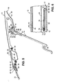
- einen abgebrochenen Schnitt durch das an einem vorderen Querholm eines Karosserierahmens des Fahrzeugs befestigte Fahrzeugdachmodul gemäß Fig. 1 entsprechend der versetzten Schnittverlaufslinie IV-IV in Fig. 3, wobei sich die geschnittene, als Sonnenblende dienende Klappe in ihrer Nichtgebrauchslage befindet,
- Fig. 5
- einen hinsichtlich des Schnittverlaufs der Fig. 4 entsprechenden, abgebrochenen Schnitt durch das Fahrzeugdachmodul gemäß Fig. 1, wobei sich die geschnittene, als Sonnenblende dienende Klappe in ihrer Gebrauchslage befindet, und
- Fig. 6
- einen abgebrochenen Schnitt durch das Fahrzeugdachmodul gemäß Fig. 1 im Bereich eines Seitenwandabschnitts und eines Federelements, die der dargestellten Klappe zugeordnet sind, entsprechend der Schnittverlaufslinie VI-VI in Fig. 3.
- Fig. 1
- 3 shows a broken perspective view of an inner shell of a vehicle roof module mounted on a vehicle, seen from the vehicle interior, with flaps provided thereon, which serve as sun visors and are in their non-use position,
- Fig. 2
- FIG. 1 shows a broken perspective view of the inner shell according to FIG. 1 corresponding to the blinking angle and detail of the illustration in FIG. 1, the flaps serving as sun visors being in their position of use,
- Fig. 3
- 1, a broken perspective view of the inner shell according to FIG. 1 corresponding to the representation in FIG. 1, spring elements assigned to the flaps, side wall sections as well as guiding and holding devices, which cannot be seen from the vehicle interior, ie are hidden, are indicated by dashed lines,
- Fig. 4
- 2 shows a broken-away section through the vehicle roof module according to FIG. 1, which is attached to a front cross member of a body frame of the vehicle, in accordance with the offset cutting line IV-IV in FIG. 3, the cut flap serving as a sun visor being in its non-use position,
- Fig. 5
- 4, broken off section corresponding to the section of FIG. 4 through the vehicle roof module according to FIG. 1, the sectioned flap serving as a sun visor being in its position of use, and
- Fig. 6
- 1 in the region of a side wall section and a spring element which are assigned to the flap shown, corresponding to the section line VI-VI in FIG. 3.
Die Figuren zeigen eine aus einem Schaumkunststoff geformte
Innenschale 10 für ein Fahrzeugdachmodul 12 als Beispiel für
ein Modulteil an Fahrzeugkarosserien, wobei der Innenschale 10
wenigstens eine, im dargestellten Ausführungsbeispiel zwei
Klappen 14 zugeordnet sind, die wahlweise von einer in den Fig.
1, 3, 4 und 6 gezeigten Nichtgebrauchslage in eine in den Fig.
2 und 5 gezeigte Gebrauchslage und umgekehrt bewegt werden können.
Die Klappen 14 dienen im dargestellten Ausführungsbeispiel
als Sonnenblenden, können statt dessen oder zusätzlich aber
auch den Zugang zu einem Funktionselement (nicht dargestellt)
und/oder einem Hohlraum 16 des Fahrzeugdachmoduls 12 ermöglichen.
Wesentlich ist, daß die Klappen 14 als Teil der Innenschale
10 ausgebildet sind und in ihrer Nichtgebrauchslage im
wesentlichen oberflächenbündig mit den an die jeweilige Klappe
14 angrenzenden Bereichen der Innenschale 10 abschließen, wie
insbesondere die Fig. 1, 4 und 6 zeigen.The figures show one molded from a foam
Gemäß den Fig. 1 bis 3 umfaßt das Fahrzeugdachmodul 12 neben
der Innenschale 10 mit den Klappen 14 u.a. eine zentral angeordnete
Innenraumleuchte 18, die in die Innenschale 10 eingelassen
ist und im wesentlichen bündig mit dieser abschließt,
sowie an jeder seiner beiden Seiten angeordnete Haltegriffe 20,
die sich an bequem erreichbaren Anbringungsorten für die Fahrzeuginsassen
befinden. Das Fahrzeugdachmodul 12 ist in den
Figuren in einem bereits am Karosserierahmen des Fahrzeugs montierten
Zustand gezeigt, wobei von dem Fahrzeug die Windschutzscheibe
22, die A-Säule 24 sowie eine Seitenscheibe 26 in den
Fig. 1 bis 3 zu erkennen sind. Ein vorderes Querteil des Karosserierahmens
ist in den Fig. 4 bis 6 mit 28 bezeichnet.According to FIGS. 1 to 3, the
Wie des weiteren insbesondere den Fig. 4 und 5 entnommen werden
kann, ist die Innenschale 10 des Fahrzeugdachmoduls 12 aus
einem Schaumkunststoff geformt, der bei dem gezeigten Ausführungsbeispiel
auf eine starre Dachhaut 30 aufgeschäumt ist. Mit
anderen Worten gesagt ist die Innenschale 10 an das Fahrzeugdachmodul
12 angeschäumt. Die starre Dachhaut 30 besteht aus
einem tiefgezogenen Metallblech, beispielsweise Aluminiumblech,
oder kann aus einer vakuumverformten Kunststoffolie gebildet
sein. Die Fig. 4 und 5 zeigen ferner, daß die Innenschale 10 im
Bereich der zur Auflage auf den Karosserierahmen vorgesehenen
Außenränder des Fahrzeugdachmoduls 12 in zwei Schichten 32, 34
aufgeteilt ist, von denen die obere Schicht 32 auf den Karosserierahmen
aufgelegt ist, während die untere Schicht 34 einstückig
mit den Klappen 14 ausgebildet ist, wie noch näher beschrieben
werden wird, und auch zur Verkleidung des Karosserierahmens
dient. Es wurde bereits eingangs erwähnt, daß die
Innenschale 10 grundsätzlich auch separat vom jeweiligen Karosserieteil
hergestellt und sodann nachträglich mit Hilfe von geeigneten
Befestigungsmitteln am jeweiligen Karosserieteil ggf.
auch lösbar befestigt werden kann.As can be seen in particular from FIGS. 4 and 5
can, the
Geeignete Werkstoffe für die Innenschale 10 sind Hartschaumkunststoffe
auf PUR-Basis, die durch dem Kunststoff vor dem
Aufschäumen einverleibte Faserstoffe, beispielsweise Glasfaserabschnitte,
armiert sein können. Aber auch in die Schäumform
eingelegte Gewebe, Gewirke, Vliese und dergleichen sind als Armierung
geeignet. Durch das Aufschäumen der armierten Innenschale
10, deren obere Schicht 32 gemäß den Fig. 4 und 5 bis zu
einer Randabkantung 36 der Dachhaut 30 reicht, entsteht ein
sandwichartiges Verbunddachmodul hoher Formbeständigkeit und
Festigkeit. Alle Konturen der Innenschale 10 einschließlich der
unteren Schicht 34 und ihrer Profilierungen werden durch entsprechende
Formgebung der Schäumform (nicht dargestellt) gebildet.Suitable materials for the
Die dem Fahrzeuginnenraum zugewandte Innenfläche der Innenschale
10 ist im dargestellten Ausführungsbeispiel zur Ausbildung
eines Dachhimmels mit einem Bezugsmaterial 38 beschichtet,
welches ausreichend flexibel ist, um sich der Innenfläche der
Innenschale 10 anzupassen. Durch das Bezugsmaterial 38 kann die
Innenschale 10 den jeweiligen Erfordernissen entsprechend
leicht hinsichtlich des äußeren Erscheinungsbilds (Farbe, Material)
der sonstigen Innenausstattung des Fahrzeugs angepaßt
werden. So kann das Bezugsmaterial 38 aus einem textilen Flächengebilde,
Leder, einem Leder- oder Velourslederimitat oder
einer dekorativen Kunststoffolie bestehen, je nach den jeweiligen
Design-Wünschen. The inner surface of the inner shell facing the
Im Bereich der Auflage auf den Karosserierahmen ist die obere
Schicht 32 der Innenschale 10 mit umlaufend eingeformten Aufnahmenuten
40 versehen, in welchen das Fahrzeugdachmodul 12
gegenüber dem Karosserierahmen abdichtende, in den Fig. 4 und 5
lediglich schematisch dargestellte Kleberaupen 42 aufgenommen
sind, die auch der Befestigung des Fahrzeugdachmoduls 12 am
Karosserierahmen dienen. Den Hauptanteil der Befestigung übernehmen
im dargestellten Ausführungsbeispiel jedoch zumindest am
in Fahrtrichtung vorderen Rand des Fahrzeugdachmoduls 12 vorgesehene
Befestigungsschrauben 44, welche zugeordnete Befestigungslöcher
im vorderen Querteil 28 des Karosserierahmens von
unten durchgreifen und in Gewindebohrungen eingeschraubt sind,
die in einem der oberen Schicht 32 angeschäumten Metallprofil
46 ausgebildet sind. Aus Fig. 5 ist ersichtlich, daß die Befestigungsschrauben
44 vom Fahrzeuginnenraum aus leicht zugänglich
sind, wenn sich die Klappen 14 in ihrer Gebrauchslage befinden.In the area of the support on the body frame is the upper one
Wie den Fig. 4 und 5 des weiteren zu entnehmen ist, ist auf
einen Rand der Windschutzscheibe 22 ein elastomeres Dichtprofil
48 aufgesteckt, welches mit einer vorspringenden Außenlippe 50
abdichtend der Außenfläche der Dachhaut 30 anliegt, während
eine vorspringende Innenlippe 52 des Dichtprofils 48 abdichtend
der Randabkantung 36 der Dachhaut 30 anliegt. Zwischen der
Windschutzscheibe 22 und einem nach außen vorspringenden
Flansch des vorderen Querteils 28 des Karosserierahmens übernimmt
eine weitere Kleberaupe 54 die Befestigung und Abdichtung
der Windschutzscheibe 22 an bzw. gegenüber der Fahrzeugkarosserie.As can be seen from FIGS. 4 and 5, is on
an edge of the
Gemäß den Fig. 4 und 5 ist die hier einstückig mit der unteren
Schicht 34 der Innenschale 10 geformte Klappe 14 an ihrem in
den Fig. 4 und 5 rechten bzw. oberen Rand 56 über ein Scharnier
58 gelenkig mit dem in diesen Figuren rechten Teil der unteren
Schicht 34 der Innenschale 10 verbunden. Das bei dem dargestellten
Ausführungsbeispiel in Fahrtrichtung des Fahrzeugs gesehen
vor der als Sonnenblende dienenden Klappe 14 liegende
Scharnier 58 ist hierbei in der Art eines Filmscharniers durch
einen in der Dicke reduzierten Abschnitt 60 der unteren Schicht
34 der Innenschale 10 ausgebildet. Ein solcher in der Dicke reduzierter
Abschnitt 60 läßt sich leicht durch entsprechende
Vorsprünge in der Schäumform (nicht dargestellt) erzeugen. Die
sich an den Scharnierrand 56 anschließenden Seitenränder 62 der
Klappe 14 sind, wie insbesondere die Fig. 6 zeigt, in der
Nichtgebrauchslage der Klappe 14 von benachbarten Rändern 64
der unteren Schicht 34 der Innenschale 10 durch Trennfugen 66
getrennt. Auch die sich ausgehend vom freien Ende der Innenschale
10 bzw. unteren Schicht 34 bis zum Scharnier 58 erstreckenden
Trennfugen 66 lassen sich leicht durch geeignete
Vorsprünge in der Schäumform (nicht dargestellt) ausbilden.
Entsprechendes gilt für eine einstückig mit der Klappe 14 ausgebildete
Griffmulde 68, die sich am freien Ende der jeweiligen
Klappe 14 befindet.4 and 5 is in one piece with the lower here
Wie den Fig. 2 und 6 zu entnehmen ist, sind zwischen den Seitenrändern
62 der Klappe 14 und den diesen benachbarten Rändern
64 der unteren Schicht 34 der Innenschale 10 flexible Seitenwandabschnitte
70 vorgesehen, die durch Bewegen der Klappe 14
aus ihrer Nichtgebrauchslage in ihre Gebrauchslage jeweils zu
einem gemäß Fig. 2 im wesentlichen dreieckigen Flächengebilde
aufgespannt werden können, das für eine zusätzliche Abschattung
des Fahrzeuginnenraums sorgt bzw. einen seitlichen Einblick in
den Hohlraum 16 verhindert. Im dargestellten Ausführungsbeispiel
sind die Seitenwandabschnitte 70 auch durch das auf der
dem Fahrzeuginnenraum zugewandten Fläche der Innenschale 10'
vorgesehene Bezugsmaterial 38 ausgebildet. Denkbar wäre hier
aber auch eine Ausgestaltung, bei der die Seitenwandabschnitte
70 durch zusätzliche Stoff- bzw. Folienabschnitte ausgebildet
werden, die an den Seitenrändern 62 der jeweiligen Klappe 14
und den diesen gegenüberliegenden Rändern 64 der unteren
Schicht 34 geeignet befestigt sind, etwa mittels eines Klebstoffs.As can be seen in FIGS. 2 and 6, there are between the side edges
62 of the
Wie die Fig. 3 bis 6 veranschaulichen, ist auf der vom Fahrzeuginnenraum
abgewandten Seite jeder Klappe 14 in der Nähe
jedes Klappenseitenrands 62 ein Federelement 72 vorgesehen, so
daß jeder Klappe 14 zwei Federelemente 72 zugeordnet sind. Die
Federelemente 72 greifen jeweils an einem der Seitenwandabschnitte
70 an, wodurch die Federelemente 72 die Seitenwandabschnitte
70 und somit auch die jeweilige Klappe 14 in die
Nichtgebrauchslage vorspannen. Genauer gesagt handelt es sich
im dargestellten Ausführungsbeispiel bei den Federelementen 72
um einfach abgewinkelte Drahtabschnitte, die jeweils einen längeren
ersten Schenkel 74 und einen kürzeren zweiten Schenkel 76
aufweisen. Der erste Schenkel 74 des Federelements 72 ist gemäß
den Fig. 3 und 6 im wesentlichen mittig am jeweiligen Seitenwandabschnitt
70 mittels wenigstens einer Stoffschlaufe 78
fixiert, die den ersten Schenkel 74 umschlingt und auf geeignete
Weise, etwa durch Kleben und/oder Nähen am jeweiligen Seitenwandabschnitt
70 befestigt ist. Das freie Ende des zweiten
Schenkels 76 des Federelements 72 hingegen ist gemäß den Fig. 4
und 5 drehbar in einem Lagerbock 80 gelagert, welcher einstückig
mit einer nachfolgend noch näher beschriebenen Lagerschale
82 ausgebildet ist, die der Klappe 14 benachbart auf der
vom Fahrzeuginnenraum abgewandten Seite an der unteren Schicht
34 der Innenschale 10 angeschäumt ist.3 to 6 illustrate, is on the vehicle interior
opposite side of each
Es ist ersichtlich, daß die Federelemente 72 bei einem Verschwenken
der Klappe 14 aus ihrer Nichtgebrauchslage in ihre
Gebrauchslage über die sich aufspannenden Seitenwandabschnitte
70, die dabei an den ersten Schenkeln 74 der Federelemente 72
über die Stoffschlaufen 78 ziehen, bezogen auf die jeweilige
Klappe 14 nach außen aufgefedert werden. Wird die Klappe 14 aus
ihrer Gebrauchslage wieder in ihre Nichtgebrauchslage zurückgeschwenkt,
so unterstützen die dabei zurückfedernden Federelemente
72 die Schwenkbewegung, in dem deren erste Schenkel 74
über die Stoffschlaufen 78 an den Seitenwandabschnitten 70 und
somit der Klappe 14 ziehen, wobei die Seitenwandabschnitte 70
auch von den Trennfugen 66 bezogen auf die jeweilige Klappe 14
nach innen weggezogen werden. In der Nichtgebrauchslage der
Klappe 14 kommen die Seitenwandabschnitte 70 und die Federelemente
72 sodann unmittelbar oberhalb der Klappe 14 zu liegen,
wie die Fig. 6 zeigt. Zwar liegen im dargestellten Ausführungsbeispiel
das Scharnier 58 und die zueinander ausgefluchteten
Drehachsen der zweiten Schenkel 76 der Federelemente 72 im jeweils
zugeordneten Lagerbock 80 nicht auf einer gemeinsamen
Achse. Bei der Schwenkbewegung der Klappe 14 sind jedoch ggf.
Ausgleichsbewegungen der beteiligten Teile infolge einer gewissen
Nachgiebigkeit des Scharniers 58 und der Elastizität der
Federelemente 72 möglich.It can be seen that the
Weiterhin ist bei dem dargestellten Ausführungsbeispiel eine in
den Fig. 4 und 5 gezeigte Führungseinrichtung für die Schwenkbewegung
der jeweiligen Klappe 14 vorgesehen, die komplementär
ineinandergreifende, die Führung der Klappe 14 bewirkende
Kreisbogenabschnitte aufweist, welche bezüglich der Schwenkachse
der Klappe 14 zentriert angeordnet sind. Genauer gesagt
ist zu beiden Querseiten der jeweiligen Klappe 14 eine Lagerschale
84 dem Scharnier 58 benachbart auf der vom Fahrzeuginnenraum
abgewandten Seite der Klappe 14 an der Klappe 14 angeschäumt,
wobei sich von jeder Lagerschale 84 ein kreisbogenförmiges
Ende 86 wegerstreckt, welches jeweils einen der erwähnten
Kreisbogenabschnitte ausbildet. Die anderen Kreisbogenabschnitte
werden durch kreisbogenförmige Schlitze 88 ausgebildet,
die in den der jeweiligen Klappe 14 benachbart an der
unteren Schicht 34 der Innenschale 10 angeschäumten Lagerschalen
82 vorgesehen sind. Wie die Fig. 4 und 5 veranschaulichen,
sind die kreisbogenförmigen Enden 86 der klappenseitigen
Lagerschalen 84 verschiebbar und im wesentlichen radialspielfrei
in den kreisbogenförmigen Schlitzen 88 der innenschalenseitigen
Lagerschalen 82 aufgenommen.Furthermore, in the illustrated embodiment, an in
4 and 5 shown guide device for the pivoting movement
the
Die vorzugsweise aus einem geeigneten Kunststoff bestehenden
Lagerschalen 82, 84 bilden zudem auch eine Halteeinrichtung zur
lösbaren Fixierung der jeweiligen Klappe 14 in ihrer Nichtgebrauchslage
bzw. ihrer Gebrauchslage aus, wie abschließend beschrieben
werden soll. Diese Halteeinrichtung weist zu beiden
Querseiten der entsprechenden Klappe 14 jeweils zwei Rastnuten
90, 92 auf, von denen die eine Rastnut 90 der Nichtgebrauchslage
der Klappe 14 (Fig. 4) zugeordnet ist, während die andere
Rastnut 92 der Gebrauchslage der Klappe 14 (Fig. 5) zugeordnet
ist. Wie die Fig. 4 und 5 des weiteren zeigen, sind die Rastnuten
90, 92 geeignet winkelbeabstandet am kreisbogenförmigen
Schlitz 88 der jeweiligen Lagerschale 82 ausgebildet, d.h. die
Rastnuten 90, 92 sind im dargestellten Ausführungsbeispiel bezüglich
des nicht bewegbaren Teils der Innenschale 10 ortsfest.
Schließlich hat die Halteeinrichtung zu beiden Querseiten der
entsprechenden Klappe 14 auch jeweils eine in die Rastnuten 90,
92 am kreisbogenförmigen Schlitz 88 der jeweiligen Lagerschale
82 einrastbare Rastnase 94, die endseitig am kreisbogenförmigen
Ende 86 der entsprechenden Lagerschale 84 ausgebildet, d.h. der
jeweiligen Klappe 14 zugeordnet ist.The preferably made of a suitable
Es ist ersichtlich, daß die beschriebene Führungseinrichtung
eine geführte bzw. definierte Schwenkbewegung um die Schwenkachse
der jeweiligen Klappe 14 gestattet, während sie Winkelbewegungen
der Klappe 14 in der Klappenebene ebenso wie translatorische
Höhenbewegungen der Klappe 14 im wesentlichen verhindert.
Translatorische Querbewegungen der Klappe 14 hingegen
werden im wesentlichen durch das Scharnier 58 verhindert. Die
beschriebene Halteeinrichtung sorgt dabei für definierte Endstellungen
der jeweiligen Klappe 14 in ihrer Nichtgebrauchslage
bzw. ihrer Gebrauchslage, wobei die Halteeinrichtung die Klappe
14 in ihrer Gebrauchslage auch gegen die Kraft der Federelemente
72 hält.It can be seen that the guide device described
a guided or defined swivel movement around the swivel axis
each
Es wurde bereits eingangs erwähnt, daß den jeweiligen Erfordernissen
entsprechend anstelle oder zusätzlich zu der beschriebenen
Halteeinrichtung eine Verrastung der Klappe 14 in ihrer
Nichtgebrauchslage mittels eines Clips, einer Haltefeder, einer
Rastnase od. dergl. (nicht dargestellt) am freien, d.h. nicht
scharnierten, in Fig. 4 linken Ende der Klappe 14 möglichst
ist, die mit einem bezüglich der Innenschale 10 bzw. der Karosserie
ortsfesten Gegenstück, z.B. einer Rastnut (nicht dargestellt)
oder einem Blechvorsprung des vorderen Querteils 28
verrastet werden kann.It was mentioned at the beginning that the respective requirements
accordingly instead of or in addition to that described
Holding device a latching of the
Es wird eine aus einem Schaumkunststoff geformte Innenschale für Fahrzeugkarosserien, insbesondere ein Fahrzeugdach oder Fahrzeugdachmodul, offenbart, der wenigstens eine Klappe zugeordnet ist, die wahlweise von einer Nichtgebrauchslage in eine Gebrauchslage und umgekehrt bewegbar ist. Vorzugsweise dient die Klappe als Sonnenblende und/oder ermöglicht den Zugang zu einem Funktionselement und/oder Hohlraum. Erfindungsgemäß ist die Klappe als Teil der Innenschale ausgebildet und schließt in ihrer Nichtgebrauchslage im wesentlichen oberflächenbündig mit den an die Klappe angrenzenden Bereichen der Innenschale ab. Im Ergebnis wird eine u.a. sehr platzsparende Ausbildung der Klappenanordnung erzielt. It becomes an inner shell molded from a foam plastic for vehicle bodies, in particular a vehicle roof or Vehicle roof module, disclosed, assigned to at least one flap which is optionally from a non-use position to a Use position and vice versa is movable. Preferably serves the flap as a sun visor and / or gives access to a functional element and / or cavity. According to the invention the flap is formed as part of the inner shell and closes in their non-use position essentially flush with the surface the areas of the inner shell adjacent to the flap. in the The result is a very space-saving design of the flap arrangement achieved.
- 1010
- Innenschaleinner shell
- 1212
- FahrzeugdachmodulVehicle roof module
- 1414
- Klappeflap
- 1616
- Hohlraumcavity
- 1818
- InnenraumleuchteInterior light
- 2020
- Haltegriffhandle
- 2222
- WindschutzscheibeWindshield
- 2424
- A-SäuleA column
- 2626
- Seitenscheibeside window
- 2828
- vorderes Querteilfront cross member
- 3030
- Dachhautroof
- 3232
- obere Schichtupper layer
- 3434
- untere SchichtLower class
- 3636
- RandabkantungRandabkantung
- 3838
- Bezugsmaterialreference material
- 4040
- Aufnahmenutreceiving groove
- 4242
- Kleberaupeadhesive bead
- 4444
- Befestigungsschraubefixing screw
- 4646
- Metallprofilmetal profile
- 4848
- Dichtprofilsealing profile
- 5050
- Außenlippeouter lip
- 5252
- Innenlippeinner lip
- 5454
- Kleberaupeadhesive bead
- 5656
- Scharnierrandhinge edge
- 5858
- Scharnierhinge
- 6060
- verjüngter Abschnitttapered section
- 6262
- Seitenrandmargin
- 6464
- Randedge
- 6666
- Trennfugeparting line
- 6868
- Griffmuldegrip
- 7070
- SeitenwandabschnittSidewall portion
- 7272
- Federelementspring element
- 7474
- erster Schenkel first leg
- 7676
- zweiter Schenkelsecond leg
- 7878
- Stoffschlaufefabric loop
- 8080
- Lagerbockbearing block
- 8282
- Lagerschalebearing shell
- 8484
- Lagerschalebearing shell
- 8686
- kreisbogenförmiges Endearcuate end
- 8888
- kreisbogenförmiger Schlitzcircular slot
- 9090
- Rastnutlocking groove
- 9292
- Rastnutlocking groove
- 9494
- Rastnaselocking lug
Claims (18)
Applications Claiming Priority (2)
| Application Number | Priority Date | Filing Date | Title |
|---|---|---|---|
| DE10236595A DE10236595A1 (en) | 2002-08-09 | 2002-08-09 | Inner shell for vehicle bodies |
| DE10236595 | 2002-08-09 |
Publications (2)
| Publication Number | Publication Date |
|---|---|
| EP1388446A2 true EP1388446A2 (en) | 2004-02-11 |
| EP1388446A3 EP1388446A3 (en) | 2004-04-07 |
Family
ID=30128800
Family Applications (1)
| Application Number | Title | Priority Date | Filing Date |
|---|---|---|---|
| EP03016743A Withdrawn EP1388446A3 (en) | 2002-08-09 | 2003-07-23 | Inner liner for vehicle body |
Country Status (3)
| Country | Link |
|---|---|
| US (1) | US6908136B2 (en) |
| EP (1) | EP1388446A3 (en) |
| DE (1) | DE10236595A1 (en) |
Cited By (1)
| Publication number | Priority date | Publication date | Assignee | Title |
|---|---|---|---|---|
| FR3017575A1 (en) * | 2014-02-18 | 2015-08-21 | Peugeot Citroen Automobiles Sa | ARRANGEMENT OF AN INTERIOR GALLERY IN THE CABIN OF A VEHICLE |
Families Citing this family (11)
| Publication number | Priority date | Publication date | Assignee | Title |
|---|---|---|---|---|
| US6991276B2 (en) * | 2003-05-20 | 2006-01-31 | Mccauley Alvin D | Luggage loft assembly |
| DE102004005484B4 (en) * | 2004-02-04 | 2011-05-26 | GM Global Technology Operations LLC, ( n. d. Ges. d. Staates Delaware ), Detroit | Motor vehicle with a stowage device arranged on the roof |
| US20080073927A1 (en) * | 2006-09-22 | 2008-03-27 | Lear Corporation | Vehicle trim component storage compartment and method of making same |
| US20080100081A1 (en) * | 2006-10-26 | 2008-05-01 | Lear Corporation | Vehicle interior storage compartment |
| DE102007015709B4 (en) * | 2007-01-25 | 2009-09-03 | Webasto Ag | vehicle roof |
| FR2929201A1 (en) * | 2008-03-27 | 2009-10-02 | Renault Sas | CONSOLE OF A MOTOR VEHICLE |
| US8038199B2 (en) * | 2008-05-21 | 2011-10-18 | Marcus Automotive, Llc | Visor |
| US20110109117A1 (en) * | 2009-11-10 | 2011-05-12 | Marcus Automotive, LLC. | Pivoted visor assembly |
| US8925995B2 (en) | 2011-10-03 | 2015-01-06 | Marcus Automotive, Llc | Rotatable side window visor and glare shield |
| JP5820223B2 (en) * | 2011-10-06 | 2015-11-24 | 豊和繊維工業株式会社 | Soundproof sheet for automobile, method for producing the same, and dash silencer for automobile using the soundproof sheet |
| CN102582531A (en) * | 2012-02-29 | 2012-07-18 | 重庆长安汽车股份有限公司 | Automobile roof decorating strip |
Citations (3)
| Publication number | Priority date | Publication date | Assignee | Title |
|---|---|---|---|---|
| DE19947238A1 (en) | 1999-09-30 | 2001-04-12 | Meritor Automotive Gmbh | Vehicle roof |
| DE19959812A1 (en) | 1999-12-11 | 2001-06-21 | Meritor Automotive Gmbh | Sun visor arrangement on a motor vehicle roof module |
| DE10116593A1 (en) | 2001-04-03 | 2002-10-17 | Arvinmeritor Gmbh | vehicle roof |
Family Cites Families (15)
| Publication number | Priority date | Publication date | Assignee | Title |
|---|---|---|---|---|
| DE2445408A1 (en) * | 1973-10-04 | 1975-04-17 | Einar Sigfrid Willgren | GLARE PROTECTION DEVICE FOR VEHICLES |
| US3953067A (en) * | 1974-09-18 | 1976-04-27 | Isola Richard A | Vehicle headliner construction |
| IT1208808B (en) * | 1985-05-31 | 1989-07-10 | Fiat Auto Spa | PAVILION FOR A VEHICLE AND PROCEDURE FOR ITS CONSTRUCTION |
| US4674789A (en) * | 1986-02-13 | 1987-06-23 | Prince Corporation | Sun shield system |
| US5269060A (en) * | 1988-06-10 | 1993-12-14 | United Technologies Automotive, Inc. | Method of aligning and installing an automobile headliner by a previously attached sunshade assembly |
| US4958878A (en) * | 1989-08-21 | 1990-09-25 | Prince Corporation | Headliner with integral visor |
| US5823611A (en) * | 1995-09-18 | 1998-10-20 | Prince Corporation | Headliner with integral impact absorption panels |
| DE19709016C2 (en) * | 1997-03-06 | 1999-05-27 | Rockwell International Gmbh | Vehicle roof and method for mounting the vehicle roof on a body |
| DE19741265C1 (en) * | 1997-09-19 | 1998-10-08 | Bayerische Motoren Werke Ag | Glove box cover for motor vehicle door |
| JP3099784B2 (en) * | 1997-09-26 | 2000-10-16 | トヨタ自動車株式会社 | Vehicle interior mounting structure with head protection airbag bag |
| US6234570B1 (en) * | 1999-03-10 | 2001-05-22 | Lear Corporation | Integration of sunglass storage holder with pull handle assembly |
| DE19951659C2 (en) * | 1999-10-26 | 2002-07-25 | Arvinmeritor Gmbh | Vehicle roof, in particular motor vehicle roof |
| DE19959809B4 (en) * | 1999-12-11 | 2005-08-04 | Arvinmeritor Gmbh | Roof module for motor vehicles |
| US6296293B1 (en) * | 2000-04-28 | 2001-10-02 | Lear Corporation | Slidable auxiliary sun visor assembly |
| GB0205482D0 (en) | 2002-03-08 | 2002-04-24 | Bae Systems Plc | Improvements in or relating to infra red camera calibration |
-
2002
- 2002-08-09 DE DE10236595A patent/DE10236595A1/en not_active Ceased
-
2003
- 2003-07-23 EP EP03016743A patent/EP1388446A3/en not_active Withdrawn
- 2003-08-08 US US10/638,127 patent/US6908136B2/en not_active Expired - Fee Related
Patent Citations (3)
| Publication number | Priority date | Publication date | Assignee | Title |
|---|---|---|---|---|
| DE19947238A1 (en) | 1999-09-30 | 2001-04-12 | Meritor Automotive Gmbh | Vehicle roof |
| DE19959812A1 (en) | 1999-12-11 | 2001-06-21 | Meritor Automotive Gmbh | Sun visor arrangement on a motor vehicle roof module |
| DE10116593A1 (en) | 2001-04-03 | 2002-10-17 | Arvinmeritor Gmbh | vehicle roof |
Cited By (1)
| Publication number | Priority date | Publication date | Assignee | Title |
|---|---|---|---|---|
| FR3017575A1 (en) * | 2014-02-18 | 2015-08-21 | Peugeot Citroen Automobiles Sa | ARRANGEMENT OF AN INTERIOR GALLERY IN THE CABIN OF A VEHICLE |
Also Published As
| Publication number | Publication date |
|---|---|
| DE10236595A1 (en) | 2004-02-26 |
| EP1388446A3 (en) | 2004-04-07 |
| US6908136B2 (en) | 2005-06-21 |
| US20040066054A1 (en) | 2004-04-08 |
Similar Documents
| Publication | Publication Date | Title |
|---|---|---|
| DE19959809B4 (en) | Roof module for motor vehicles | |
| DE19709016C2 (en) | Vehicle roof and method for mounting the vehicle roof on a body | |
| EP1024972B1 (en) | Motor vehicle door | |
| EP1088749B1 (en) | Vehicle roof | |
| DE69705875T3 (en) | External frame, shaped frame module | |
| EP1187734B1 (en) | Vehicle door with door casing and method for the production thereof | |
| DE69203615T2 (en) | Method for manufacturing a vehicle door, in particular for an automobile; Sub-unit for the application of the method and door which is obtained by the application of the method. | |
| DE19801842A1 (en) | Door of motor vehicle, providing better side impact resistance and more room for interior equipping | |
| DE10233280B4 (en) | Vehicle roof module | |
| DE10101450A1 (en) | Vehicle roof, in particular motor vehicle roof | |
| EP1388446A2 (en) | Inner liner for vehicle body | |
| EP1651458B1 (en) | Automobile door | |
| WO2002060720A2 (en) | Door subassembly for the door of a motor vehicle | |
| DE20114907U1 (en) | Module for a vehicle door comprises elements carrying certain functional items and elements forming a door lining, with both groups of elements constituted so that a single module carrier is produced | |
| DE10334143B4 (en) | Motor vehicle door | |
| DE10144166A1 (en) | Lock for vehicle door has lock housing and lock cover formed in one piece therewith through film hinge or similar | |
| DE102018122796A1 (en) | vehicle door | |
| EP1106489A2 (en) | A sun visor assembly for a roof unit of motor vehicles, | |
| DE10116593B4 (en) | vehicle roof | |
| DE102006009701A1 (en) | Automotive door has outer shell separated from interior lining by part-covered functional panel | |
| DE60022924T2 (en) | Interior part of a vehicle door, corresponding door and method for assembling such a door | |
| EP1841610B1 (en) | Unit support comprising window pane guide rails for a motor vehicle door | |
| EP2200849A1 (en) | Assembly carrier for a motor vehicle, particularly for a vehicle door, and vehicle door | |
| DE10234526B4 (en) | Motor vehicle door | |
| DE10047818A1 (en) | Fastening device for interior lining esp. roof lining for motor vehicles consists of strip profile, attached to vehicle body, with groove to hold pressed-in roof lining edge |
Legal Events
| Date | Code | Title | Description |
|---|---|---|---|
| PUAI | Public reference made under article 153(3) epc to a published international application that has entered the european phase |
Free format text: ORIGINAL CODE: 0009012 |
|
| AK | Designated contracting states |
Kind code of ref document: A2 Designated state(s): AT BE BG CH CY CZ DE DK EE ES FI FR GB GR HU IE IT LI LU MC NL PT RO SE SI SK TR |
|
| AX | Request for extension of the european patent |
Extension state: AL LT LV MK |
|
| PUAL | Search report despatched |
Free format text: ORIGINAL CODE: 0009013 |
|
| AK | Designated contracting states |
Kind code of ref document: A3 Designated state(s): AT BE BG CH CY CZ DE DK EE ES FI FR GB GR HU IE IT LI LU MC NL PT RO SE SI SK TR |
|
| AX | Request for extension of the european patent |
Extension state: AL LT LV MK |
|
| RIC1 | Information provided on ipc code assigned before grant |
Ipc: 7B 60J 3/02 A |
|
| 17P | Request for examination filed |
Effective date: 20040423 |
|
| AKX | Designation fees paid |
Designated state(s): DE FR IT NL |
|
| STAA | Information on the status of an ep patent application or granted ep patent |
Free format text: STATUS: THE APPLICATION HAS BEEN WITHDRAWN |
|
| 18W | Application withdrawn |
Effective date: 20070426 |