EP1388372A1 - Rotary atomizer turbine and rotary atomizer - Google Patents
Rotary atomizer turbine and rotary atomizer Download PDFInfo
- Publication number
- EP1388372A1 EP1388372A1 EP03017425A EP03017425A EP1388372A1 EP 1388372 A1 EP1388372 A1 EP 1388372A1 EP 03017425 A EP03017425 A EP 03017425A EP 03017425 A EP03017425 A EP 03017425A EP 1388372 A1 EP1388372 A1 EP 1388372A1
- Authority
- EP
- European Patent Office
- Prior art keywords
- turbine
- nozzles
- intermediate chamber
- rotary
- inlet
- Prior art date
- Legal status (The legal status is an assumption and is not a legal conclusion. Google has not performed a legal analysis and makes no representation as to the accuracy of the status listed.)
- Granted
Links
- 239000011248 coating agent Substances 0.000 claims abstract description 8
- 238000007664 blowing Methods 0.000 claims abstract description 7
- 238000000576 coating method Methods 0.000 claims abstract description 6
- 238000011144 upstream manufacturing Methods 0.000 claims description 5
- 238000009434 installation Methods 0.000 claims 1
- 230000002349 favourable effect Effects 0.000 description 5
- 238000013461 design Methods 0.000 description 4
- 238000010422 painting Methods 0.000 description 3
- 230000002093 peripheral effect Effects 0.000 description 3
- 230000008901 benefit Effects 0.000 description 2
- 238000013016 damping Methods 0.000 description 1
- 238000011161 development Methods 0.000 description 1
- 230000018109 developmental process Effects 0.000 description 1
- 238000005516 engineering process Methods 0.000 description 1
- 230000001771 impaired effect Effects 0.000 description 1
- 238000004519 manufacturing process Methods 0.000 description 1
- 238000003801 milling Methods 0.000 description 1
- 238000012986 modification Methods 0.000 description 1
- 230000004048 modification Effects 0.000 description 1
- 239000003973 paint Substances 0.000 description 1
- 230000010349 pulsation Effects 0.000 description 1
- 238000007493 shaping process Methods 0.000 description 1
- 239000007921 spray Substances 0.000 description 1
- 238000012546 transfer Methods 0.000 description 1
Images

Classifications
-
- B—PERFORMING OPERATIONS; TRANSPORTING
- B05—SPRAYING OR ATOMISING IN GENERAL; APPLYING FLUENT MATERIALS TO SURFACES, IN GENERAL
- B05B—SPRAYING APPARATUS; ATOMISING APPARATUS; NOZZLES
- B05B5/00—Electrostatic spraying apparatus; Spraying apparatus with means for charging the spray electrically; Apparatus for spraying liquids or other fluent materials by other electric means
- B05B5/025—Discharge apparatus, e.g. electrostatic spray guns
- B05B5/04—Discharge apparatus, e.g. electrostatic spray guns characterised by having rotary outlet or deflecting elements, i.e. spraying being also effected by centrifugal forces
- B05B5/0415—Driving means; Parts thereof, e.g. turbine, shaft, bearings
-
- B—PERFORMING OPERATIONS; TRANSPORTING
- B05—SPRAYING OR ATOMISING IN GENERAL; APPLYING FLUENT MATERIALS TO SURFACES, IN GENERAL
- B05B—SPRAYING APPARATUS; ATOMISING APPARATUS; NOZZLES
- B05B3/00—Spraying or sprinkling apparatus with moving outlet elements or moving deflecting elements
- B05B3/003—Spraying or sprinkling apparatus with moving outlet elements or moving deflecting elements with braking means, e.g. friction rings designed to provide a substantially constant revolution speed
Definitions
- the invention relates to a Rotationszerstäuberturbine for driving a bell cup in a rotary atomizer for a Coating plant according to the preamble of claim 1 and a rotary atomizer according to claim 13 having such Rotationszerstäuberturbine.
- the speed of the compressed air turbine is in the range of 15,000 to 80,000 rpm. At high speeds of the compressed air turbine However, it may happen that the drive power during Opening the main needle and then feeding Coating agent is insufficient to increase the speed of the compressed air turbine to keep constant at the desired value. On This way, the speed of the air turbine could open break the main needle of the rotary atomizer by up to 20%, whereby the coating quality would be impaired.
- the invention is therefore the object of the known Compressed air turbines for driving a bell cup in a rotary atomizer to improve that a speed drop when opening the main needle is largely avoided.
- the object is, starting from the well-known known Rotationszerstäuberturbine according to the preamble of the claim 1, by the characterizing features of claim 1 and with respect to a rotary atomizer having such Rotary atomizing turbine by the features of claim 13 solved.
- the rotary atomizing turbine according to the invention has a rotatable stored Turbinenrad'mit several turbine blades, wherein the turbine blades of a plurality of nozzles with a drive gas be blown.
- the turbine wheel may have a circular disk of the individual turbine blades protrude axially.
- the turbine wheel is open on both sides in the axial direction, wherein the turbine blades arranged on the lateral surface of a rotating hub are.
- the individual turbine blades can be shaped have only in the radial direction, but not in is curved in the axial direction. This is manufacturing technology favorable, since the individual turbine blades then in the milling process can be produced. In particular, in an axial Direction closed on one side and unilaterally open turbine wheel This design of the turbine blades is advantageous since the turbine blades from a circular disc whose peripheral edge can be milled out.
- the individual turbine blades both in the axial direction and in radial Direction are curved to provide optimal momentum transfer from to reach the drive gas on the drive blades.
- a Such shaping of the turbine blades is particularly suitable then on, if the turbine blades are made separately and only then be attached to the turbine wheel.
- the individual turbine blades can each have a chamber or have a receiving opening, but it is also possible that the individual turbine blades two chambers or Have receiving wells, the side by side in the axial direction are arranged.
- the rotary atomizer turbine according to the invention a plurality of nozzles for blowing the turbine blades with a drive gas with the nozzles preferably as Laval nozzles, such as they e.g. in DE 10233199, or similar to one Laval nozzle are formed, which is aerodynamically favorable.
- the individual nozzles for blowing the turbine blades are in the rotary atomizer turbine according to the invention of a Intermediate chamber supplied with the drive gas, the intermediate chamber According to the invention at least two inlets for feeding having the drive gas.
- the present invention leaves the previous path to increase the drive power, on the cross section of the inlet to the intermediate chamber was increased, whereas the invention instead of a single enlarged inlet several inlets to the intermediate chamber provides.
- the intermediate chamber preferably also causes a damping of Gas flows, because the intermediate chamber has a storage capacity having.
- branch of the intermediate chamber at least three nozzles for blowing the turbine blades but there are also a larger number of nozzles possible to increase the speed of the bell cup in the future reach or the bell cup with a larger torque drive.
- the intermediate chamber with respect to the axis of rotation of the Turbine arranged annularly circumferentially, wherein the Intermediate chamber for example by an angular range of 90 ° to 270 ° with respect to the axis of rotation of the turbine wheel can extend.
- the rotary atomizer turbine surrounds the annular intermediate chamber the Turbine wheel in radial direction outside.
- the annular intermediate chamber in the axial direction is arranged next to the turbine wheel, wherein the drive gas is injected laterally into the turbine wheel.
- the annular intermediate chamber is in particular then possible if the turbine wheel in the axial direction one-sided or open on both sides.
- the individual nozzles with respect the axis of rotation of the turbine wheel at an angular distance which is an odd multiple of the angular distance of adjacent ones Turbine blades is.
- Such an arrangement of the nozzles and the turbine blades cause the individual nozzles regardless of the position of the turbine wheel each different Relative positions to the nearest turbine blade exhibit.
- the advantage of this is that the drive torque the Rotationszerstäuberturbine only a slight pulsation has, since the drive air at the individual nozzles not simultaneously impinges on a respective drive blade, but phase.
- At least one of the nozzles for blowing the branches Turbine blades between two inlets of the intermediate chamber which is aerodynamically favorable.
- the nozzles in the Essentially without offset in a hollow cylindrical turbine chamber go over, whereas the known Rotationszerstäuberturbinen Having nozzles that leak downstream in the circumferential direction, resulting in the inner circumferential surface of the cylindrical turbine chamber forms a paragraph in the axial direction.
- the invention features the hollow cylindrical turbine chamber So preferably a smooth, paragraph free inner contour, the only in the immediate region of the Düsen' trim the nozzle opening is interrupted.
- nozzles are in the intermediate chamber on the downstream side of the supply lines.
- the individual nozzles on the circumference distributed asymmetrically arranged.
- the individual inlets open with respect to the axis of rotation of the turbine wheel axially into the intermediate chamber, which in particular favorable at an annular circumferential intermediate chamber is.
- the inlets into the intermediate chamber already arranged or shaped so that the supports natural flow movement within the intermediate chamber becomes.
- the inlets into the intermediate chamber be inclined in the circumferential direction in the flow direction, so that the drive gas already entering the intermediate chamber has a flow component in the circumferential direction.
- the invention also includes a complete rotary atomizer with the invention described above Rotationszerstäuberturbine
- the individual inlets of the intermediate chamber are respectively individually with separate supply lines for the drive gas connected.
- the separate supply lines allow for a separate control or regulation of the supply of the drive gas for the two inlets.
- the separate supply lines allow with a sufficient overall cross-section of the supply lines relatively small individual cross sections, so that the individual Cables better managed within a coating system can be.
- the supply lines consist of at least one Part of their length from hoses that are flexible and also in an arrangement of the rotary atomizer on a painting robot can follow the movement of the painting robot.
- the individual supply lines to the inlets of the intermediate chamber of the rotary atomizing turbine merged upstream and are from a common Powered by driving gas source.
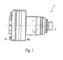
- FIG. 1 shows a Rotationszerstäuberturbine 1, in a rotary atomizer of a paint shop can be used and drives a Glockentellerwelle 2, not on the bell-plate shaft 2 for simplicity illustrated bell plate can be mounted.
- a turbine wheel 3 On the bell-plate shaft 2, a turbine wheel 3 is mounted, which consists essentially of a circular disc on the peripheral edge bell-plate side numerous turbine blades 4 are formed.
- the housing part 6 is annular and surrounds in mounted state, the turbine wheel 3 in the radial direction outside, such that the interior of the housing part 6 is a cylindrical turbine chamber forms, in which the turbine wheel 3 is running.
- the Laval nozzles 9-11 are equipped with an annular intermediate chamber 12, which is disposed within the housing part 6 and with respect to the rotational axis of the turbine wheel 3 in the circumferential direction rotates over an angular range of about 130 °.
- the annular intermediate chamber 12 is milled into the housing part 6 and in the axial direction unilaterally open, wherein the annular Intermediate chamber 12 in the assembled state on its open Side is covered by the housing part 7.
- annular intermediate chamber 12 open in the axial direction two inlets 13, 14, each having a circular cross-section having a diameter of 5 mm.
- the two inlets 13, 14 are each separated with supply lines connected, in the bell plate facing away from the end face the Rotationszerstäuberturbine 1 in corresponding separate drive air connections 15 lead, where in the drawings nur'der Drive terminal 15 is shown for the inlet 13.
- the Inlets 13, 14 in the upstream half of the intermediate chamber 12 arranged, reducing the natural flow direction is supported within the intermediate chamber 12.
- the same Purpose also serves the arrangement of Lavalle nozzles 9-11, the mostly on the downstream side of the inlets 13, 14 are arranged.
- the rotary atomizing turbine 1 in the housing part 6, a further nozzle 16 to the turbine wheel 3 brake by the individual turbine blades 4 in reversed direction with brake air to be blown.
Landscapes
- Nozzles (AREA)
- Electrostatic Spraying Apparatus (AREA)
- Vaporization, Distillation, Condensation, Sublimation, And Cold Traps (AREA)
- Agricultural Chemicals And Associated Chemicals (AREA)
Abstract
Description
Die Erfindung betrifft eine Rotationszerstäuberturbine zum Antrieb eines Glockentellers in einem Rotationszerstäuber für eine Beschichtungsanlage gemäß dem Oberbegriff des Anspruchs 1 sowie einen Rotationszerstäuber gemäß Anspruch 13 mit einer derartigen Rotationszerstäuberturbine.The invention relates to a Rotationszerstäuberturbine for driving a bell cup in a rotary atomizer for a Coating plant according to the preamble of claim 1 and a rotary atomizer according to claim 13 having such Rotationszerstäuberturbine.
In modernen Lackieranlagen werden bekanntermaßen Rotationszerstäuber eingesetzt, bei denen ein sogenannter Glockenteller von einer Druckluftturbine mit hohen Drehzahlen angetrieben wird. Der Glockenteller ist hierbei in der Regel kegelstumpfförmig und erweitert sich in Sprührichtung, wobei das aufzutragende Beschichtungsmittel in dem kegelstumpfförmigen Glockenteller aufgrund der Zentrifugalkräfte axial und insbesondere radial beschleunigt wird, so dass an der Glockentellerabrisskante ein kegelförmiger Sprühsträhl entsteht.In modern painting plants are known rotary atomizer used in which a so-called bell plate of a compressed air turbine is driven at high speeds. The bell plate is hereby usually frustoconical and expands in spray direction, wherein the coating agent to be applied in the frusto-conical bell cup due to the centrifugal forces axially and in particular radially accelerated becomes, so that at the bell-plate tear-off edge a cone-shaped Sprühsträhl arises.
Die Drehzahl der Druckluftturbine liegt hierbei im Bereich von 15.000 bis 80.000 U/Min. Bei hohen Drehzahlen der Druckluftturbine kann es jedoch vorkommen, dass die Antriebsleistung beim Öffnen der Hauptnadel und einer darauffolgenden Zuführung von Beschichtungsmittel nicht ausreicht, um die Drehzahl der Druckluftturbine auf dem gewünschten Wert konstant zu halten. Auf diese Weise könnte die Drehzahl der Druckluftturbine beim Öffnen der Hauptnadel des Rotationszerstäubers um bis zu 20% einbrechen, wodurch die Lackierqualität beeinträchtigt würde.The speed of the compressed air turbine is in the range of 15,000 to 80,000 rpm. At high speeds of the compressed air turbine However, it may happen that the drive power during Opening the main needle and then feeding Coating agent is insufficient to increase the speed of the compressed air turbine to keep constant at the desired value. On This way, the speed of the air turbine could open break the main needle of the rotary atomizer by up to 20%, whereby the coating quality would be impaired.
Der Erfindung liegt somit die Aufgabe zugrunde, die bekannten Druckluftturbinen zum Antrieb eines Glockentellers in einem Rotationszerstäuber dahingehend zu verbessern, dass ein Drehzahleinbruch beim Öffnen der Hauptnadel weitgehend vermieden wird. The invention is therefore the object of the known Compressed air turbines for driving a bell cup in a rotary atomizer to improve that a speed drop when opening the main needle is largely avoided.
Die Aufgabe wird, ausgehend von der eingangs beschriebenen bekannten
Rotationszerstäuberturbine gemäß dem Oberbegriff des Anspruchs
1, durch die kennzeichnenden Merkmale des Anspruchs 1
und hinsichtlich eines Rotationszerstäubers mit einer derartigen
Rotationszerstäuberturbine durch die Merkmale des Anspruchs 13
gelöst.The object is, starting from the well-known known
Rotationszerstäuberturbine according to the preamble of the claim
1, by the characterizing features of claim 1
and with respect to a rotary atomizer having such
Rotary atomizing turbine by the features of
Die erfindungsgemäße Rotationszerstäuberturbine weist ein drehbar gelagertes Turbinenrad'mit mehreren Turbinenschaufeln auf, wobei die Turbinenschaufeln von mehreren Düsen mit einem Antriebsgas angeblasen werden.The rotary atomizing turbine according to the invention has a rotatable stored Turbinenrad'mit several turbine blades, wherein the turbine blades of a plurality of nozzles with a drive gas be blown.
Hinsichtlich der konstruktiven Gestaltung des Turbinenrades und der Turbinenschaufeln bestehen vielfältige Möglichkeiten, die im Folgenden ohne Anspruch auf Vollständigkeit kurz beschrieben werden.With regard to the structural design of the turbine wheel and The turbine blades have many possibilities in the Described briefly below without claim to completeness become.
So kann das Turbinenrad eine kreisförmige Scheibe aufweisen, von der die einzelnen Turbinenschaufeln axial abstehen.Thus, the turbine wheel may have a circular disk of the individual turbine blades protrude axially.
Anstelle eines derartigen einseitig geschlossenen und einseitig offenen Turbinenrades ist es jedoch auch möglich, ein axial beidseitig geschlossenes Turbinenrad einzusetzen, bei dem die Turbinenschaufeln in axialer Richtung zwischen zwei kreisförmigen Scheiben angeordnet sind. Die Abführung des eingeblasenen Antriebsgases kann hierbei durch Auslässe in der Nähe der Drehachse des Turbinenrades erfolgen, wobei die Auslässe einseitig oder beidseitig in den kreisförmigen Scheiben vorgesehen sein können.Instead of such a one-sided closed and one-sided However, it is also possible to open an axial turbine to use both sides closed turbine wheel, in which the Turbine blades in the axial direction between two circular Disks are arranged. The discharge of the injected Drive gas can in this case by outlets in the vicinity of the axis of rotation the turbine wheel, the outlets on one side or be provided on both sides in the circular discs can.
Darüber hinaus besteht auch die Möglichkeit, dass das Turbinenrad in axialer Richtung beidseitig offen ist, wobei die Turbinenschaufeln auf der Mantelfläche einer rotierenden Nabe angeordnet sind. In addition, there is also the possibility that the turbine wheel is open on both sides in the axial direction, wherein the turbine blades arranged on the lateral surface of a rotating hub are.
Die Erfindung ist jedoch nicht auf die vorstehend beispielhaft beschriebenen konstruktiven Gestaltungen des Turbinenrades beschränkt.However, the invention is not illustrative of the above described constructive designs of the turbine wheel limited.
'Auch hinsichtlich der konstruktiven Gestaltung der einzelnen Turbinenschaufeln bestehen vielfältige Möglichkeiten, die im Folgenden ohne Anspruch auf Vollständigkeit kurz beschrieben werden.'Also with regard to the structural design of the individual Turbine blades have many possibilities in the Described briefly below without claim to completeness become.
Beispielsweise können die einzelnen Turbinenschaufeln eine Formgebung aufweisen, die nur in radialer Richtung, nicht aber in axialer Richtung gekrümmt ist. Dies ist fertigungstechnisch günstig, da die einzelnen Turbinenschaufeln dann im Fräsverfahren hergestellt werden können. Insbesondere bei einem in axialer Richtung einseitig geschlossenen und einseitig offenen Turbinenrad ist diese Gestaltung der Turbinenschaufeln vorteilhaft, da die Turbinenschaufeln dabei aus einer kreisförmigen Scheibe an deren Umfangsrand herausgefräst werden können.For example, the individual turbine blades can be shaped have only in the radial direction, but not in is curved in the axial direction. This is manufacturing technology favorable, since the individual turbine blades then in the milling process can be produced. In particular, in an axial Direction closed on one side and unilaterally open turbine wheel This design of the turbine blades is advantageous since the turbine blades from a circular disc whose peripheral edge can be milled out.
Es ist jedoch alternativ auch möglich, dass die einzelnen Turbinenschaufeln sowohl in axialer Richtung als auch in radialer Richtung gekrümmt sind, um eine optimale Impulsübertragung von dem Antriebsgas auf die Antriebsschaufeln zu erreichen. Eine derartige Formgebung der Turbinenschaufeln bietet sich insbesondere dann an, wenn die Turbinenschaufeln separat gefertigt und erst anschließend an dem Turbinenrad befestigt werden.However, it is alternatively also possible that the individual turbine blades both in the axial direction and in radial Direction are curved to provide optimal momentum transfer from to reach the drive gas on the drive blades. A Such shaping of the turbine blades is particularly suitable then on, if the turbine blades are made separately and only then be attached to the turbine wheel.
Ferner können die einzelnen Turbinenschaufeln jeweils eine Kammer bzw. eine Aufnahmeöffnung aufweisen, jedoch ist es auch möglich, dass die einzelnen Turbinenschaufeln zwei Kammern bzw. Aufnahmevertiefungen aufweisen, die in axialer Richtung nebeneinander angeordnet sind.Furthermore, the individual turbine blades can each have a chamber or have a receiving opening, but it is also possible that the individual turbine blades two chambers or Have receiving wells, the side by side in the axial direction are arranged.
Weiterhin weist die erfindungsgemäße Rotationszerstäuberturbine mehrere Düsen zum Anblasen der Turbinenschaufeln mit einem Antriebsgas auf, wobei die Düsen vorzugsweise als Laval-Düsen, wie sie z.B. in der DE 10233199 erläutert sind, oder ähnlich einer Laval-Düse ausgebildet sind, was strömungstechnisch günstig ist.Furthermore, the rotary atomizer turbine according to the invention a plurality of nozzles for blowing the turbine blades with a drive gas with the nozzles preferably as Laval nozzles, such as they e.g. in DE 10233199, or similar to one Laval nozzle are formed, which is aerodynamically favorable.
Die einzelnen Düsen zum Anblasen der Turbinenschaufeln werden bei der erfindungsgemäßen Rotationszerstäuberturbine von einer Zwischenkammer mit dem Antriebsgas versorgt, wobei die Zwischenkammer erfindungsgemäß mindestens zwei Einlässe zur Zuführung des Antriebsgases aufweist. Durch die Verwendung mehrerer Einlässe zu der Zwischenkammer zur Zuführung des Antriebsgases wird die Antriebsleistung der Rotationszerstäuberturbine erhöht, so dass es auch beim Öffnen der Hauptnadel nicht oder nur in geringem Maße zu einem Drehzahleinbruch kommt. Die vorliegende Erfindung verlässt also den bisherigen Weg zur Erhöhung der Antriebsleistung, auf dem der Querschnitt des Einlasses zu der Zwischenkammer erhöht wurde, wohingegen die Erfindung anstelle eines einzelnen vergrößerten Einlasses mehrere Einlässe zu der Zwischenkammer vorsieht. Ein weiterer Vorteil mehrerer Einlässe in der Zwischenkammer ist darin zu sehen, dass diese in der Zwischenkammer strömungstechnisch günstig angeordnet werden können.The individual nozzles for blowing the turbine blades are in the rotary atomizer turbine according to the invention of a Intermediate chamber supplied with the drive gas, the intermediate chamber According to the invention at least two inlets for feeding having the drive gas. By using multiple inlets to the intermediate chamber for supplying the drive gas increases the drive power of the rotary atomizer turbine, so that it does not or only slightly when opening the main needle Dimensions to a speed drop comes. The present invention leaves the previous path to increase the drive power, on the cross section of the inlet to the intermediate chamber was increased, whereas the invention instead of a single enlarged inlet several inlets to the intermediate chamber provides. Another benefit of multiple inlets the intermediate chamber can be seen in the intermediate chamber can be conveniently arranged fluidically.
Die Zwischenkammer bewirkt vorzugsweise auch eine Dämpfung der Gasströmungen, weil die Zwischenkammer eine Speicherfähigkeit aufweist.The intermediate chamber preferably also causes a damping of Gas flows, because the intermediate chamber has a storage capacity having.
In einer bevorzugten Ausführungsform der Erfindung zweigen von der Zwischenkammer mindestens drei Düsen zum Anblasen der Turbinenschaufeln ab, jedoch ist auch eine größere Anzahl von Düsen möglich, um in Zukunft höhere Drehzahlen des Glockentellers zu erreichen oder den Glockenteller mit einem größeren Drehmoment anzutreiben.In a preferred embodiment of the invention branch of the intermediate chamber at least three nozzles for blowing the turbine blades but there are also a larger number of nozzles possible to increase the speed of the bell cup in the future reach or the bell cup with a larger torque drive.
Vorzugsweise ist die Zwischenkammer bezüglich der Drehachse des Turbinenrads ringförmig umlaufend angeordnet, wobei sich die Zwischenkammer beispielsweise um einen Winkelbereich von 90° bis 270° bezüglich der Drehachse des Turbinenrads erstrecken kann.Preferably, the intermediate chamber with respect to the axis of rotation of the Turbine arranged annularly circumferentially, wherein the Intermediate chamber for example by an angular range of 90 ° to 270 ° with respect to the axis of rotation of the turbine wheel can extend.
In einer bevorzugten Ausführungsform der erfindungsgemäßen Rotationszerstäuberturbine umgibt die ringförmige Zwischenkammer das Turbinenrad in radialer Richtung außen. Es ist jedoch auch möglich, dass die ringförmige Zwischenkammer in axialer Richtung neben dem Turbinenrad angeordnet ist, wobei das Antriebsgas seitlich in das Turbinenrad eingeblasen wird. Eine derartige Anordnung der ringförmigen Zwischenkammer ist insbesondere dann möglich, wenn das Turbinenrad in axialer Richtung einseitig oder beidseitig offen ist.In a preferred embodiment of the rotary atomizer turbine according to the invention surrounds the annular intermediate chamber the Turbine wheel in radial direction outside. However, it is also possible that the annular intermediate chamber in the axial direction is arranged next to the turbine wheel, wherein the drive gas is injected laterally into the turbine wheel. Such an arrangement the annular intermediate chamber is in particular then possible if the turbine wheel in the axial direction one-sided or open on both sides.
In einer Variante der Erfindung weisen die einzelnen-Düsen bezüglich der Drehachse des Turbinenrades einen Winkelabstand auf, der ein ungeradzahliges Vielfaches des Winkelabstandes benachbarter Turbinenschaufeln ist. Eine derartige Anordnung der Düsen und der Turbinenschaufeln hat zur Folge, dass die einzelnen Düsen unabhängig von der Stellung des Turbinenrades jeweils unterschiedliche Relativpositionen zu der nächstgelegenen Turbinenschaufel aufweisen. Vorteilhaft daran ist, dass das Antriebsmoment der Rotationszerstäuberturbine nur ein geringes Pulsieren aufweist, da die Antriebsluft an den einzelnen Düsen nicht gleichzeitig auf jeweils eine Antriebsschaufel auftrifft, sondern phasenverschoben.In a variant of the invention, the individual nozzles with respect the axis of rotation of the turbine wheel at an angular distance, which is an odd multiple of the angular distance of adjacent ones Turbine blades is. Such an arrangement of the nozzles and the turbine blades cause the individual nozzles regardless of the position of the turbine wheel each different Relative positions to the nearest turbine blade exhibit. The advantage of this is that the drive torque the Rotationszerstäuberturbine only a slight pulsation has, since the drive air at the individual nozzles not simultaneously impinges on a respective drive blade, but phase.
Vorzugsweise zweigt mindestens eine der Düsen zum Anblasen der Turbinenschaufeln zwischen zwei Einlässen der Zwischenkammer ab, was strömungstechnisch günstig ist.Preferably, at least one of the nozzles for blowing the branches Turbine blades between two inlets of the intermediate chamber, which is aerodynamically favorable.
Darüber hinaus ist vorzugsweise vorgesehen, dass die Düsen im Wesentlichen absatzlos in eine hohlzylindrische Turbinenkammer übergehen, wohingegen die bekannten Rotationszerstäuberturbinen Düsen aufweisen, die stromabwärts in Umfangsrichtung auslaufen, wodurch sich an der inneren Mantelfläche der zylindrischen Turbinenkammer ein Absatz in axialer Richtung bildet. In dieser Variante der Erfindung weist die hohlzylindrische Turbinenkammer also vorzugsweise eine glatte, absatzfreie Innenkontur auf, die lediglich im unmittelbaren Bereich der Düsen'durch die Düsenöffnung unterbrochen wird.In addition, it is preferably provided that the nozzles in the Essentially without offset in a hollow cylindrical turbine chamber go over, whereas the known Rotationszerstäuberturbinen Having nozzles that leak downstream in the circumferential direction, resulting in the inner circumferential surface of the cylindrical turbine chamber forms a paragraph in the axial direction. In this variant The invention features the hollow cylindrical turbine chamber So preferably a smooth, paragraph free inner contour, the only in the immediate region of the Düsen'durch the nozzle opening is interrupted.
Weiterhin ist es strömungstechnisch günstig, in der Zwischenkammer auf der stromabwärts gelegenen Seite jedes Einlasses mehr Düsen anzuordnen, als auf der stromaufwärts gelegenen Seite.Furthermore, it is aerodynamically favorable, in the intermediate chamber on the downstream side of each inlet more To arrange nozzles, as on the upstream side.
Vorzugsweise liegen sogar sämtliche Düsen in der Zwischenkammer auf der stromabwärts gelegenen Seite der Zuleitungen.Preferably, even all nozzles are in the intermediate chamber on the downstream side of the supply lines.
Weiterhin ist es möglich, dass die einzelnen Düsen über den umfang verteilt unsymmetrisch angeordnet sind. Beispielsweise kann sich die ringförmige Zwischenkammer bezüglich der Drehachse des Turbinenrades über einen Winkelbereich von nur rund 110° erstrecken, wobei sämtliche Düsen innerhalb dieses Winkelbereichs angeordnet sind.Furthermore, it is possible that the individual nozzles on the circumference distributed asymmetrically arranged. For example, can the annular intermediate chamber with respect to the axis of rotation of Turbine wheel over an angular range of only about 110 ° extend, with all nozzles arranged within this angular range are.
Vorzugsweise münden die einzelnen Einlässe bezüglich der Drehachse des Turbinenrads axial in die Zwischenkammer, was insbesondere bei einer ringförmig umlaufenden Zwischenkammer günstig ist. Es ist jedoch auch möglich, dass die Einlässe in die Zwischenkammer bereits so angeordnet oder geformt sind, dass die natürliche Strömungsbewegung innerhalb der Zwischenkammer unterstützt wird. Beispielsweise können die Einlässe in die Zwischenkammer in Umfangsrichtung in Strömungsrichtung geneigt sein, so dass das Antriebsgas bereits beim Eintreten in die Zwischenkammer eine Strömungskomponente in Umfangsrichtung aufweist.Preferably, the individual inlets open with respect to the axis of rotation of the turbine wheel axially into the intermediate chamber, which in particular favorable at an annular circumferential intermediate chamber is. However, it is also possible that the inlets into the intermediate chamber already arranged or shaped so that the supports natural flow movement within the intermediate chamber becomes. For example, the inlets into the intermediate chamber be inclined in the circumferential direction in the flow direction, so that the drive gas already entering the intermediate chamber has a flow component in the circumferential direction.
Darüber hinaus umfasst die Erfindung auch einen kompletten Rotationszerstäuber mit der vorstehend beschriebenen erfindungsgemäßen Rotationszerstäuberturbine In addition, the invention also includes a complete rotary atomizer with the invention described above Rotationszerstäuberturbine
Vorzugsweise sind die einzelnen Einlässe der Zwischenkammer jeweils einzeln mit getrennten Zuleitungen für das Antriebsgas verbunden. Die getrennten Zuleitungen ermöglichen zum einen eine getrennte Steuerung bzw. Regelung der Zufuhr des Antriebsgases für die beiden Einlässe. Zum anderen erlauben die getrennten Zuleitungen bei einem ausreichenden Gesamtquerschnitt der Zuleitungen relativ geringe Einzelquerschnitte, so dass die einzelnen Zuleitungen besser innerhalb einer Beschichtungsanlage geführt werden können.Preferably, the individual inlets of the intermediate chamber are respectively individually with separate supply lines for the drive gas connected. The separate supply lines allow for a separate control or regulation of the supply of the drive gas for the two inlets. On the other hand, the separate supply lines allow with a sufficient overall cross-section of the supply lines relatively small individual cross sections, so that the individual Cables better managed within a coating system can be.
Vorzugsweise bestehen die Zuleitungen deshalb mindestens auf einem Teil ihrer Länge aus Schläuchen, die flexibel sind und auch bei einer Anordnung des Rotationszerstäubers auf einem Lackierroboter der Bewegung des Lackierroboters folgen können.Preferably, therefore, the supply lines consist of at least one Part of their length from hoses that are flexible and also in an arrangement of the rotary atomizer on a painting robot can follow the movement of the painting robot.
In einer Variante der Erfindung sind die einzelnen Zuleitungen zu den Einlässen der Zwischenkammer der Rotationszerstäuberturbine stromaufwärts zusammengeführt und werden aus einer gemeinsamen Antriebsgasquelle gespeist.In a variant of the invention, the individual supply lines to the inlets of the intermediate chamber of the rotary atomizing turbine merged upstream and are from a common Powered by driving gas source.
In einer bevorzugten Ausführungsform der Erfindung weisen die einzelnen Zuleitungen zu den Einlässen der Zwischenkammer mindestens auf einem Teil ihrer Länge einen Querschnitt zwischen 5 mm2 und 80 mm2 auf. Andere vorteilhafte Weiterbildungen der Erfindung sind in den Unteransprüchen gekennzeichnet oder werden nachstehend zusammen mit der Beschreibung des bevorzugten Ausführungsbeispiels der Erfindung anhand der Figuren näher erläutert. Es zeigen:
- Figur 1
- eine Seitenansicht einer erfindungsgemäßen Rotationszerstäuberturbine,
- Figur 2
- eine Explosionsdarstellung der Rotationszerstäuberturbine aus Figur 1 sowie
- Figur 3
- einen Düsenring der Rotationszerstäuberturbine aus den Figuren 1 und 2.
- FIG. 1
- a side view of a Rotationszerstäuberturbine invention,
- FIG. 2
- an exploded view of the rotary atomizing turbine of Figure 1 and
- FIG. 3
- a nozzle ring of the rotary atomizing turbine of Figures 1 and 2.
Die Seitenansicht in Figur 1 zeigt eine Rotationszerstäuberturbine 1, die in einem Rotationszerstäuber einer Lackieranlage eingesetzt werden kann und eine Glockentellerwelle 2 antreibt, wobei auf der Glockentellerwelle 2 ein zur Vereinfachung nicht dargestellter Glockenteller montiert werden kann.The side view in Figure 1 shows a Rotationszerstäuberturbine 1, in a rotary atomizer of a paint shop can be used and drives a Glockentellerwelle 2, not on the bell-plate shaft 2 for simplicity illustrated bell plate can be mounted.
Auf der Glockentellerwelle 2 ist ein Turbinenrad 3 angebracht, das im Wesentlichen aus einer kreisförmigen Scheibe besteht, an deren Umfangsrand glockentellerseitig zahlreiche-Turbinenschaufeln 4 angeformt sind.On the bell-plate shaft 2, a turbine wheel 3 is mounted, which consists essentially of a circular disc on the peripheral edge bell-plate side numerous turbine blades 4 are formed.
Weiterhin weist die erfindungsgemäße Rotationszerstäuberturbine 1 mehrere Gehäuseteile 5-8 auf, wie insbesondere aus der Explosionsdarstellung aus Figur 2 ersichtlich ist.Furthermore, the rotary atomizer turbine according to the invention 1 several housing parts 5-8, as in particular from the exploded view can be seen from Figure 2.
Das Gehäuseteil 6 ist kreisringförmig ausgebildet und umgibt im montierten Zustand das Turbinenrad 3 in radialer Richtung außen, so dass das Innere des Gehäuseteils 6 eine zylindrische Turbinenkammer bildet, in der das Turbinenrad 3 läuft.The housing part 6 is annular and surrounds in mounted state, the turbine wheel 3 in the radial direction outside, such that the interior of the housing part 6 is a cylindrical turbine chamber forms, in which the turbine wheel 3 is running.
Aus der inneren Mantelfläche des ringförmigen Gehäuseteils 6 münden mehrere Laval-Düsen 9-11 nach innen in die zylindrische Turbinenkammer, wodurch während des Betriebs die einzelnen Turbinenschaufeln 4 des Turbinenrads 3 angeblasen werden.From the inner circumferential surface of the annular housing part. 6 several Laval nozzles 9-11 open inwards into the cylindrical one Turbine chamber, whereby during operation the individual turbine blades 4 of the turbine wheel 3 are blown.
Die Laval-Düsen 9-11 sind mit einer ringförmigen Zwischenkammer
12 verbunden, die innerhalb des Gehäuseteils 6 angeordnet ist
und bezüglich der Drehachse des Turbinenrads 3 in Umfangsrichtung
über einen Winkelbereich von ungefähr 130° umläuft. Die
ringförmige Zwischenkammer 12 ist in das Gehäuseteil 6 eingefräst
und in axialer Richtung einseitig offen, wobei die ringförmige
Zwischenkammer 12 im montierten Zustand auf ihrer offenen
Seite durch das Gehäuseteil 7 abgedeckt wird. The Laval nozzles 9-11 are equipped with an annular
In die ringförmige Zwischenkammer 12 münden in axialer Richtung
zwei Einlässe 13, 14, die jeweils einen kreisförmigen Querschnitt
mit einem Durchmesser von 5 mm aufweisen.In the annular
Die beiden Einlässe 13, 14 sind jeweils getrennt mit Zuleitungen
verbunden, die in der dem Glockenteller abgewandten Stirnseite
der Rotationszerstäuberturbine 1 in entsprechende getrennte Antriebsluftanschlüsse
15 münden, wobei in den Zeichnungen nur'der
Antriebsanschluss 15 für den Einlass 13 dargestellt ist.The two
Innerhalb der ringförmig umlaufenden Zwischenkammer 12 sind die
Einlässe 13, 14 in der stromaufwärts gelegenen Hälfte der Zwischenkammer
12 angeordnet, wodurch die natürliche Strömungsrichtung
innerhalb der Zwischenkammer 12 unterstützt wird. Dem gleichen
Zweck dient auch die Anordnung der Lavalle-Düsen 9-11, die
mehrheitlich auf der stromabwärts gelegenen Seite der Einlässe
13, 14 angeordnet sind.Within the annular peripheral
Ferner weist die erfindungsgemäße Rotationszerstäuberturbine 1
in dem Gehäuseteil 6 eine weitere Düse 16 auf, um das Turbinenrad
3 abzubremsen, indem die einzelnen Turbinenschaufeln 4 in
umgekehrter Richtung mit Bremsluft angeblasen werden.Furthermore, the rotary atomizing turbine 1 according to the invention
in the housing part 6, a
Die Erfindung ist nicht auf das vorstehend beschriebene bevorzugte Ausführungsbeispiel beschränkt. Vielmehr ist eine Vielzahl von Varianten und Abwandlungen möglich, die ebenfalls von dem Erfindungsgedanken Gebrauch machen und deshalb in den Schutzbereich fallen.The invention is not preferred to that described above Embodiment limited. Rather, a variety Variants and modifications possible, also from the Inventive idea make use and therefore in the scope fall.
Claims (17)
einem drehbar gelagerten Turbinenrad (3) mit mehreren Turbinenschaufeln (4),
mehreren Düsen (9-11) zum Anblasen der Turbinenschaufeln (4) mit einem Antriebsgas,
einer mit den Düsen (9-11) verbundenen Zwischenkammer (12) zur Aufnahme des Antriebsgases,
wobei die Zwischenkammer (12) einen ersten Einlass (13) zur Zuführung des Antriebsgases aufweist,
dadurch gekennzeichnet, dass
die Zwischenkammer (12) mindestens einen zweiten Einlass (14) zur Zuführung des Antriebsgases aufweist.Rotary atomiser turbine (1) for driving a bell cup in a rotary atomizer for a coating installation, with
a rotatably mounted turbine wheel (3) with a plurality of turbine blades (4),
a plurality of nozzles (9-11) for blowing the turbine blades (4) with a drive gas,
an intermediate chamber (12) connected to the nozzles (9-11) for receiving the drive gas,
the intermediate chamber (12) having a first inlet (13) for supplying the drive gas,
characterized in that
the intermediate chamber (12) has at least one second inlet (14) for supplying the drive gas.
Applications Claiming Priority (2)
| Application Number | Priority Date | Filing Date | Title |
|---|---|---|---|
| DE10236017A DE10236017B3 (en) | 2002-08-06 | 2002-08-06 | Rotary atomizer turbine and rotary atomizer |
| DE10236017 | 2002-08-06 |
Publications (2)
| Publication Number | Publication Date |
|---|---|
| EP1388372A1 true EP1388372A1 (en) | 2004-02-11 |
| EP1388372B1 EP1388372B1 (en) | 2004-11-10 |
Family
ID=30128749
Family Applications (1)
| Application Number | Title | Priority Date | Filing Date |
|---|---|---|---|
| EP03017425A Expired - Lifetime EP1388372B1 (en) | 2002-08-06 | 2003-08-01 | Rotary atomizer turbine and rotary atomizer |
Country Status (5)
| Country | Link |
|---|---|
| US (1) | US7131601B2 (en) |
| EP (1) | EP1388372B1 (en) |
| AT (1) | ATE281888T1 (en) |
| DE (2) | DE10236017B3 (en) |
| ES (1) | ES2231751T3 (en) |
Cited By (3)
| Publication number | Priority date | Publication date | Assignee | Title |
|---|---|---|---|---|
| WO2006024861A1 (en) * | 2004-09-03 | 2006-03-09 | Gsi Group Ltd | Drive spindles |
| US9016596B2 (en) | 2007-07-20 | 2015-04-28 | Durr Systems Gmbh | Method for process diagnosis and rotary atomizer arrangement |
| WO2023174697A1 (en) | 2022-03-15 | 2023-09-21 | Dürr Systems Ag | Turbine drive for a rotary atomizer, and associated operating method |
Families Citing this family (13)
| Publication number | Priority date | Publication date | Assignee | Title |
|---|---|---|---|---|
| DE10236017B3 (en) | 2002-08-06 | 2004-05-27 | Dürr Systems GmbH | Rotary atomizer turbine and rotary atomizer |
| US20090206182A1 (en) * | 2008-01-25 | 2009-08-20 | Abb Inc. | Rotary Atomizer with an Improved Valve |
| AT506722B1 (en) * | 2008-04-21 | 2011-01-15 | Kronsteiner Martin Ing | delivery equipment |
| USD873874S1 (en) | 2012-09-28 | 2020-01-28 | Dürr Systems Ag | Axial turbine housing for a rotary atomizer for a painting robot |
| DE102010013551B4 (en) * | 2010-03-31 | 2016-12-08 | Dürr Systems Ag | Turbine rotor and drive turbine for a rotary atomizer and rotary atomizer |
| EP2505778B1 (en) * | 2010-11-29 | 2019-05-01 | NSK Ltd. | Air motor and electrostatic coating device |
| DE102010053134A1 (en) * | 2010-12-01 | 2012-06-06 | Eisenmann Ag | Nozzle head and rotary atomizer with such |
| DE102015000551A1 (en) | 2015-01-20 | 2016-07-21 | Dürr Systems GmbH | Rotationszerstäuberturbine |
| US9375734B1 (en) | 2015-06-16 | 2016-06-28 | Efc Systems, Inc. | Coating apparatus turbine having internally routed shaping air |
| CN106761608B (en) * | 2017-01-11 | 2022-11-18 | 山东科技大学 | Liquid drainage and gas production device and method for natural gas underground gas storage |
| CN110680020A (en) * | 2018-07-06 | 2020-01-14 | 湖南中烟工业有限责任公司 | Smoking set |
| USD901626S1 (en) * | 2018-11-28 | 2020-11-10 | Graco Minnesota Inc. | Airless sprayer cartridge |
| DE102022133678A1 (en) | 2022-12-16 | 2024-06-27 | Dürr Systems Ag | Drive turbine for a rotary atomizer |
Citations (3)
| Publication number | Priority date | Publication date | Assignee | Title |
|---|---|---|---|---|
| US4589597A (en) * | 1983-10-03 | 1986-05-20 | Graco Inc. | Rotary atomizer spray painting device |
| US4700896A (en) * | 1986-04-11 | 1987-10-20 | Toyota Jidosha Kabushiki Kaisha | Rotary type electrostatic spray painting device |
| US5353995A (en) * | 1992-06-10 | 1994-10-11 | Sames S.A. | Device with rotating ionizer head for electrostatically spraying a powder coating product |
Family Cites Families (8)
| Publication number | Priority date | Publication date | Assignee | Title |
|---|---|---|---|---|
| US4896834A (en) * | 1984-08-30 | 1990-01-30 | The Devilbiss Company | Rotary atomizer apparatus |
| US5633306A (en) * | 1992-12-03 | 1997-05-27 | Ransburg Corporation | Nonincendive rotary atomizer |
| US5697559A (en) * | 1995-03-15 | 1997-12-16 | Nordson Corporation | Electrostatic rotary atomizing spray device |
| DE19621072A1 (en) * | 1996-05-24 | 1997-11-27 | Gema Volstatic Ag | Electrostatic spray device |
| US5853126A (en) * | 1997-02-05 | 1998-12-29 | Illinois Tool Works, Inc. | Quick disconnect for powder coating apparatus |
| US5803372A (en) * | 1997-04-03 | 1998-09-08 | Asahi Sunac Corporation | Hand held rotary atomizer spray gun |
| DE10053295C2 (en) * | 2000-10-27 | 2002-10-31 | Eisenmann Lacktechnik Kg | High-speed rotary atomizer for applying powder coating |
| DE10236017B3 (en) | 2002-08-06 | 2004-05-27 | Dürr Systems GmbH | Rotary atomizer turbine and rotary atomizer |
-
2002
- 2002-08-06 DE DE10236017A patent/DE10236017B3/en not_active Expired - Fee Related
-
2003
- 2003-08-01 AT AT03017425T patent/ATE281888T1/en not_active IP Right Cessation
- 2003-08-01 EP EP03017425A patent/EP1388372B1/en not_active Expired - Lifetime
- 2003-08-01 DE DE50300146T patent/DE50300146D1/en not_active Expired - Lifetime
- 2003-08-01 ES ES03017425T patent/ES2231751T3/en not_active Expired - Lifetime
- 2003-12-17 US US10/895,446 patent/US7131601B2/en active Active
Patent Citations (3)
| Publication number | Priority date | Publication date | Assignee | Title |
|---|---|---|---|---|
| US4589597A (en) * | 1983-10-03 | 1986-05-20 | Graco Inc. | Rotary atomizer spray painting device |
| US4700896A (en) * | 1986-04-11 | 1987-10-20 | Toyota Jidosha Kabushiki Kaisha | Rotary type electrostatic spray painting device |
| US5353995A (en) * | 1992-06-10 | 1994-10-11 | Sames S.A. | Device with rotating ionizer head for electrostatically spraying a powder coating product |
Cited By (5)
| Publication number | Priority date | Publication date | Assignee | Title |
|---|---|---|---|---|
| WO2006024861A1 (en) * | 2004-09-03 | 2006-03-09 | Gsi Group Ltd | Drive spindles |
| US7967552B2 (en) | 2004-09-03 | 2011-06-28 | Neil Edward Brett | Drive spindles |
| US9016596B2 (en) | 2007-07-20 | 2015-04-28 | Durr Systems Gmbh | Method for process diagnosis and rotary atomizer arrangement |
| WO2023174697A1 (en) | 2022-03-15 | 2023-09-21 | Dürr Systems Ag | Turbine drive for a rotary atomizer, and associated operating method |
| DE102022105999A1 (en) | 2022-03-15 | 2023-09-21 | Dürr Systems Ag | Turbine drive for a rotary atomizer and associated operating method |
Also Published As
| Publication number | Publication date |
|---|---|
| US20050258270A1 (en) | 2005-11-24 |
| US7131601B2 (en) | 2006-11-07 |
| DE10236017B3 (en) | 2004-05-27 |
| ATE281888T1 (en) | 2004-11-15 |
| EP1388372B1 (en) | 2004-11-10 |
| DE50300146D1 (en) | 2004-12-16 |
| ES2231751T3 (en) | 2005-05-16 |
Similar Documents
| Publication | Publication Date | Title |
|---|---|---|
| EP1388372B1 (en) | Rotary atomizer turbine and rotary atomizer | |
| EP1394364B1 (en) | Turbocharger and annular guide conduit therefor | |
| DE602005000116T2 (en) | Jet engine architecture with two fans at the front | |
| EP1318272B1 (en) | Deswirl guide for cooling air in a gas turbine rotor | |
| DE602005000974T2 (en) | Turbomachine with counter-rotating fan | |
| CH647042A5 (en) | EVAPORATION PIPE OF A TURBINE. | |
| EP2099570A1 (en) | Guiding air ring comprising a ring cavity and corresponding bell plate | |
| CH672941A5 (en) | ||
| DE102004030597A1 (en) | Turbomachine with external wheel jet generation at the stator | |
| EP2407247B1 (en) | Turbine of a rotary dispenser | |
| DE2333274A1 (en) | FAN WHEEL | |
| DE3835622C2 (en) | ||
| EP2617947B1 (en) | Aircraft gas turbine engine with adjustable fan | |
| EP1443181B1 (en) | Turbine wheel for high speed rotary tools | |
| EP0636764A1 (en) | Gasturbine with cooled rotor | |
| EP0879101B1 (en) | Workpiece descaling process | |
| EP1384514A2 (en) | Rotary sprayer and bearing for this sprayer | |
| DE102015010239B4 (en) | Torus turbine rotor drive for helicopters, multicopters or for turbo-fan aircraft | |
| EP2874558B1 (en) | Dental preparation instrument | |
| DE102006023246A1 (en) | Turbo engine e.g. aircraft engine, has fan-rotor driven into flow channel, another rotor arranged downstream to former rotor, and booster-compressor with booster-rotors that are connected with respective fan-rotors in rotating manner | |
| DE3047501A1 (en) | Wind turbine with cupola shaped blades - has deflecting baffle hub annular bases, and wing blades shaped to aerodynamic profile | |
| DE2952446C2 (en) | Particle separator for the air inlet duct of an aircraft engine | |
| DE102015000551A1 (en) | Rotationszerstäuberturbine | |
| DE102021133773B3 (en) | compressor wheel | |
| WO2010115599A1 (en) | Sprinkler |
Legal Events
| Date | Code | Title | Description |
|---|---|---|---|
| PUAI | Public reference made under article 153(3) epc to a published international application that has entered the european phase |
Free format text: ORIGINAL CODE: 0009012 |
|
| AK | Designated contracting states |
Kind code of ref document: A1 Designated state(s): AT BE BG CH CY CZ DE DK EE ES FI FR GB GR HU IE IT LI LU MC NL PT RO SE SI SK TR |
|
| AX | Request for extension of the european patent |
Extension state: AL LT LV MK |
|
| GRAP | Despatch of communication of intention to grant a patent |
Free format text: ORIGINAL CODE: EPIDOSNIGR1 |
|
| 17P | Request for examination filed |
Effective date: 20040324 |
|
| GRAS | Grant fee paid |
Free format text: ORIGINAL CODE: EPIDOSNIGR3 |
|
| GRAA | (expected) grant |
Free format text: ORIGINAL CODE: 0009210 |
|
| AKX | Designation fees paid |
Designated state(s): AT BE BG CH CY CZ DE DK EE ES FI FR GB GR HU IE IT LI LU MC NL PT RO SE SI SK TR |
|
| AK | Designated contracting states |
Kind code of ref document: B1 Designated state(s): AT BE BG CH CY CZ DE DK EE ES FI FR GB GR HU IE IT LI LU MC NL PT RO SE SI SK TR |
|
| PG25 | Lapsed in a contracting state [announced via postgrant information from national office to epo] |
Ref country code: TR Free format text: LAPSE BECAUSE OF FAILURE TO SUBMIT A TRANSLATION OF THE DESCRIPTION OR TO PAY THE FEE WITHIN THE PRESCRIBED TIME-LIMIT Effective date: 20041110 Ref country code: SK Free format text: LAPSE BECAUSE OF FAILURE TO SUBMIT A TRANSLATION OF THE DESCRIPTION OR TO PAY THE FEE WITHIN THE PRESCRIBED TIME-LIMIT Effective date: 20041110 Ref country code: SI Free format text: LAPSE BECAUSE OF FAILURE TO SUBMIT A TRANSLATION OF THE DESCRIPTION OR TO PAY THE FEE WITHIN THE PRESCRIBED TIME-LIMIT Effective date: 20041110 Ref country code: RO Free format text: LAPSE BECAUSE OF FAILURE TO SUBMIT A TRANSLATION OF THE DESCRIPTION OR TO PAY THE FEE WITHIN THE PRESCRIBED TIME-LIMIT Effective date: 20041110 Ref country code: IE Free format text: LAPSE BECAUSE OF FAILURE TO SUBMIT A TRANSLATION OF THE DESCRIPTION OR TO PAY THE FEE WITHIN THE PRESCRIBED TIME-LIMIT Effective date: 20041110 Ref country code: FI Free format text: LAPSE BECAUSE OF FAILURE TO SUBMIT A TRANSLATION OF THE DESCRIPTION OR TO PAY THE FEE WITHIN THE PRESCRIBED TIME-LIMIT Effective date: 20041110 Ref country code: EE Free format text: LAPSE BECAUSE OF FAILURE TO SUBMIT A TRANSLATION OF THE DESCRIPTION OR TO PAY THE FEE WITHIN THE PRESCRIBED TIME-LIMIT Effective date: 20041110 Ref country code: CZ Free format text: LAPSE BECAUSE OF FAILURE TO SUBMIT A TRANSLATION OF THE DESCRIPTION OR TO PAY THE FEE WITHIN THE PRESCRIBED TIME-LIMIT Effective date: 20041110 Ref country code: BG Free format text: LAPSE BECAUSE OF FAILURE TO SUBMIT A TRANSLATION OF THE DESCRIPTION OR TO PAY THE FEE WITHIN THE PRESCRIBED TIME-LIMIT Effective date: 20041110 |
|
| REG | Reference to a national code |
Ref country code: GB Ref legal event code: FG4D Free format text: NOT ENGLISH |
|
| REG | Reference to a national code |
Ref country code: CH Ref legal event code: EP |
|
| REG | Reference to a national code |
Ref country code: IE Ref legal event code: FG4D Free format text: GERMAN |
|
| REF | Corresponds to: |
Ref document number: 50300146 Country of ref document: DE Date of ref document: 20041216 Kind code of ref document: P |
|
| PG25 | Lapsed in a contracting state [announced via postgrant information from national office to epo] |
Ref country code: GR Free format text: LAPSE BECAUSE OF FAILURE TO SUBMIT A TRANSLATION OF THE DESCRIPTION OR TO PAY THE FEE WITHIN THE PRESCRIBED TIME-LIMIT Effective date: 20050210 Ref country code: DK Free format text: LAPSE BECAUSE OF FAILURE TO SUBMIT A TRANSLATION OF THE DESCRIPTION OR TO PAY THE FEE WITHIN THE PRESCRIBED TIME-LIMIT Effective date: 20050210 |
|
| PG25 | Lapsed in a contracting state [announced via postgrant information from national office to epo] |
Ref country code: HU Free format text: LAPSE BECAUSE OF FAILURE TO SUBMIT A TRANSLATION OF THE DESCRIPTION OR TO PAY THE FEE WITHIN THE PRESCRIBED TIME-LIMIT Effective date: 20050211 |
|
| REG | Reference to a national code |
Ref country code: SE Ref legal event code: TRGR |
|
| GBT | Gb: translation of ep patent filed (gb section 77(6)(a)/1977) |
Effective date: 20050218 |
|
| REG | Reference to a national code |
Ref country code: ES Ref legal event code: FG2A Ref document number: 2231751 Country of ref document: ES Kind code of ref document: T3 |
|
| REG | Reference to a national code |
Ref country code: IE Ref legal event code: FD4D |
|
| PG25 | Lapsed in a contracting state [announced via postgrant information from national office to epo] |
Ref country code: LU Free format text: LAPSE BECAUSE OF NON-PAYMENT OF DUE FEES Effective date: 20050801 Ref country code: CY Free format text: LAPSE BECAUSE OF FAILURE TO SUBMIT A TRANSLATION OF THE DESCRIPTION OR TO PAY THE FEE WITHIN THE PRESCRIBED TIME-LIMIT Effective date: 20050801 Ref country code: AT Free format text: LAPSE BECAUSE OF NON-PAYMENT OF DUE FEES Effective date: 20050801 |
|
| ET | Fr: translation filed | ||
| PG25 | Lapsed in a contracting state [announced via postgrant information from national office to epo] |
Ref country code: MC Free format text: LAPSE BECAUSE OF NON-PAYMENT OF DUE FEES Effective date: 20050831 |
|
| PLBE | No opposition filed within time limit |
Free format text: ORIGINAL CODE: 0009261 |
|
| STAA | Information on the status of an ep patent application or granted ep patent |
Free format text: STATUS: NO OPPOSITION FILED WITHIN TIME LIMIT |
|
| 26N | No opposition filed |
Effective date: 20050811 |
|
| PG25 | Lapsed in a contracting state [announced via postgrant information from national office to epo] |
Ref country code: PT Free format text: LAPSE BECAUSE OF NON-PAYMENT OF DUE FEES Effective date: 20050410 |
|
| REG | Reference to a national code |
Ref country code: CH Ref legal event code: PL |
|
| PG25 | Lapsed in a contracting state [announced via postgrant information from national office to epo] |
Ref country code: LI Free format text: LAPSE BECAUSE OF NON-PAYMENT OF DUE FEES Effective date: 20070831 Ref country code: CH Free format text: LAPSE BECAUSE OF NON-PAYMENT OF DUE FEES Effective date: 20070831 |
|
| REG | Reference to a national code |
Ref country code: FR Ref legal event code: PLFP Year of fee payment: 14 |
|
| REG | Reference to a national code |
Ref country code: DE Ref legal event code: R082 Ref document number: 50300146 Country of ref document: DE Representative=s name: V. BEZOLD & PARTNER PATENTANWAELTE - PARTG MBB, DE Ref country code: DE Ref legal event code: R081 Ref document number: 50300146 Country of ref document: DE Owner name: DUERR SYSTEMS AG, DE Free format text: FORMER OWNER: DUERR SYSTEMS GMBH, 74321 BIETIGHEIM-BISSINGEN, DE |
|
| REG | Reference to a national code |
Ref country code: DE Ref legal event code: R082 Ref document number: 50300146 Country of ref document: DE Representative=s name: V. BEZOLD & PARTNER PATENTANWAELTE - PARTG MBB, DE Ref country code: DE Ref legal event code: R081 Ref document number: 50300146 Country of ref document: DE Owner name: DUERR SYSTEMS AG, DE Free format text: FORMER OWNER: DUERR SYSTEMS AG, 74321 BIETIGHEIM-BISSINGEN, DE |
|
| REG | Reference to a national code |
Ref country code: FR Ref legal event code: PLFP Year of fee payment: 15 |
|
| REG | Reference to a national code |
Ref country code: FR Ref legal event code: PLFP Year of fee payment: 16 |
|
| PGFP | Annual fee paid to national office [announced via postgrant information from national office to epo] |
Ref country code: NL Payment date: 20220822 Year of fee payment: 20 |
|
| PGFP | Annual fee paid to national office [announced via postgrant information from national office to epo] |
Ref country code: SE Payment date: 20220819 Year of fee payment: 20 Ref country code: IT Payment date: 20220825 Year of fee payment: 20 Ref country code: GB Payment date: 20220823 Year of fee payment: 20 Ref country code: DE Payment date: 20220819 Year of fee payment: 20 |
|
| PGFP | Annual fee paid to national office [announced via postgrant information from national office to epo] |
Ref country code: FR Payment date: 20220823 Year of fee payment: 20 Ref country code: BE Payment date: 20220819 Year of fee payment: 20 |
|
| PGFP | Annual fee paid to national office [announced via postgrant information from national office to epo] |
Ref country code: ES Payment date: 20221024 Year of fee payment: 20 |
|
| P01 | Opt-out of the competence of the unified patent court (upc) registered |
Effective date: 20230512 |
|
| REG | Reference to a national code |
Ref country code: DE Ref legal event code: R071 Ref document number: 50300146 Country of ref document: DE |
|
| REG | Reference to a national code |
Ref country code: NL Ref legal event code: MK Effective date: 20230731 |
|
| REG | Reference to a national code |
Ref country code: GB Ref legal event code: PE20 Expiry date: 20230731 |
|
| REG | Reference to a national code |
Ref country code: BE Ref legal event code: MK Effective date: 20230801 |
|
| REG | Reference to a national code |
Ref country code: ES Ref legal event code: FD2A Effective date: 20230825 |
|
| REG | Reference to a national code |
Ref country code: SE Ref legal event code: EUG |
|
| PG25 | Lapsed in a contracting state [announced via postgrant information from national office to epo] |
Ref country code: GB Free format text: LAPSE BECAUSE OF EXPIRATION OF PROTECTION Effective date: 20230731 Ref country code: ES Free format text: LAPSE BECAUSE OF EXPIRATION OF PROTECTION Effective date: 20230802 |