EP1388366A2 - Verfahren und Vorrichtung zur Erhaltung von Teilchen in einer Flüssigkeitssuspension - Google Patents
Verfahren und Vorrichtung zur Erhaltung von Teilchen in einer Flüssigkeitssuspension Download PDFInfo
- Publication number
- EP1388366A2 EP1388366A2 EP03016773A EP03016773A EP1388366A2 EP 1388366 A2 EP1388366 A2 EP 1388366A2 EP 03016773 A EP03016773 A EP 03016773A EP 03016773 A EP03016773 A EP 03016773A EP 1388366 A2 EP1388366 A2 EP 1388366A2
- Authority
- EP
- European Patent Office
- Prior art keywords
- container
- fluid
- rate
- rotation
- sample
- Prior art date
- Legal status (The legal status is an assumption and is not a legal conclusion. Google has not performed a legal analysis and makes no representation as to the accuracy of the status listed.)
- Withdrawn
Links
Images


Classifications
-
- B—PERFORMING OPERATIONS; TRANSPORTING
- B01—PHYSICAL OR CHEMICAL PROCESSES OR APPARATUS IN GENERAL
- B01F—MIXING, e.g. DISSOLVING, EMULSIFYING OR DISPERSING
- B01F29/00—Mixers with rotating receptacles
- B01F29/30—Mixing the contents of individual packages or containers, e.g. by rotating tins or bottles
-
- B—PERFORMING OPERATIONS; TRANSPORTING
- B01—PHYSICAL OR CHEMICAL PROCESSES OR APPARATUS IN GENERAL
- B01F—MIXING, e.g. DISSOLVING, EMULSIFYING OR DISPERSING
- B01F35/00—Accessories for mixers; Auxiliary operations or auxiliary devices; Parts or details of general application
- B01F35/30—Driving arrangements; Transmissions; Couplings; Brakes
- B01F35/32—Driving arrangements
-
- B—PERFORMING OPERATIONS; TRANSPORTING
- B01—PHYSICAL OR CHEMICAL PROCESSES OR APPARATUS IN GENERAL
- B01F—MIXING, e.g. DISSOLVING, EMULSIFYING OR DISPERSING
- B01F35/00—Accessories for mixers; Auxiliary operations or auxiliary devices; Parts or details of general application
- B01F35/30—Driving arrangements; Transmissions; Couplings; Brakes
- B01F35/33—Transmissions; Means for modifying the speed or direction of rotation
- B01F35/331—Transmissions; Means for modifying the speed or direction of rotation alternately changing the speed of rotation
-
- B—PERFORMING OPERATIONS; TRANSPORTING
- B01—PHYSICAL OR CHEMICAL PROCESSES OR APPARATUS IN GENERAL
- B01F—MIXING, e.g. DISSOLVING, EMULSIFYING OR DISPERSING
- B01F35/00—Accessories for mixers; Auxiliary operations or auxiliary devices; Parts or details of general application
- B01F35/30—Driving arrangements; Transmissions; Couplings; Brakes
- B01F35/33—Transmissions; Means for modifying the speed or direction of rotation
- B01F35/332—Transmissions; Means for modifying the speed or direction of rotation alternately changing the direction of rotation
-
- B—PERFORMING OPERATIONS; TRANSPORTING
- B01—PHYSICAL OR CHEMICAL PROCESSES OR APPARATUS IN GENERAL
- B01F—MIXING, e.g. DISSOLVING, EMULSIFYING OR DISPERSING
- B01F2101/00—Mixing characterised by the nature of the mixed materials or by the application field
- B01F2101/23—Mixing of laboratory samples e.g. in preparation of analysing or testing properties of materials
Definitions
- U.S. Patent No. 5,439,645 to Saralegui et al. describes an apparatus, which employs a vortexer/mixer for orbitally mixing and resuspending a test tube's contents.
- the container contents are forced out of the container through an aspirating head probe after orbital rotation of a selected sample container has occurred.
- U.S. Patent No. 6,235,537 to North et al. describes an apparatus and a method for washing cells incorporating a method of resuspending the cells.
- the method and apparatus describe a test tube, containing cells to be washed, and a rotatable spindle inserted into the open top of the test tube.
- the test tube is first spun about its vertical axis by a drive motor to drive by centrifugal force the larger, more dense cells against the inner wall of the test tube.
- a washing fluid is delivered to the bottom of the test tube displacing fluid containing smaller, less dense cells, debris, and unbound agents through passageways in the spindle. This is drawn to an external reservoir. Wash fluid thus displaces and removes the unwanted supernatant.
- the wash fluid flow is stopped and the drive motor is rapidly stopped by braking.
- the rapid stopping of the test tube rotation causes the fluid inside the test tube to continue rotating, which washes over the cells at the test tube inner wall, resuspending some cells.
- the test tube may be rotated and stopped several times to increase cell recoveries.
- cells are washed by a method including application of a centrifugal force pushing the larger cells to the sidewalls and removing the smaller cells. After washing, the larger remaining cells are resuspended through rapid stopping and restarting of the drive motor.
- Surfactants in the wash solution assist in the resupension of cells showing that the rotational method of the patent alone may not be sufficient to resuspend the cells.
- the patent fails to describe a method for continuously maintaining a suspension of cells. In addition the very rapid braking required to scour pelleted cells from the tube wall is likely to damage the cells.
- streams of cells withdrawn from the container will contain an accurate representation of the cells present within the sample resulting in reliable analytical results. Also, because minimal centrifugal forces are imparted on the particles during the cycle of rotation, it is less likely that the particles will be damaged, or stratified in any way. This allows cells to be subsequently recovered after a sorting procedure and used for kinetic studies, cell culture, or other processes.
- the container holding the sample is rotated at a first calculated rate for a first calculated time interval about its longitudinal axis.
- the first rate and time interval are such that solid body rotation of the sample does not result.
- the particles are maintained suspended within the fluid and do not migrate to the container walls as a result of centrifugal forces.
- the time interval of the first rate of rotation is of a length where solid body rotation is on the threshold of occurring but does not, because the first rate of rotation is changed before it does occur.
- the second altered rate of rotation for the second calculated time interval results in a transient secondary flow of the sample producing transient motions that keep the particles suspended within the fluid and that thus agitate the sample.
- the cycle of rotation including alternating between the first and second rates, may be repeated to continuously maintain the suspension of particles within the sample. Where the second rate is changed to the first rate, transient secondary flow also occurs but in the opposite direction.
- a controller, motor, and container holder are included within the system of the invention.
- the controller is programmed to rotate the motor connected to the container holder.
- the container holder rotatably drives the container about its axis at the first and second calculated rates for the first and second time intervals for a desired number of cycles.
- the invention is advantageous in that particle settling on a bottom surface of the container is avoided because particles are continuously maintained in suspension during said cycles.
- a system of the present invention connected to an analytical device 12 of a type known in the art.
- Device 12 may be a flow cytometer, blood analyzer, or any other analytical system that analyzes particles in liquid.
- the system includes a motor controller 14 including controller circuitry (not shown) programmed to rotate a motor 16 driving a container 18 containing a sample 20 including particles 22 and fluid 24, such that a sample agitation is achieved through a desired cycle of rotation of the container 18 about a longitudinal container axis z (see Fig. 4).
- the container 18 is a test tube.
- the container may be any axisymmetric container.
- the controller 14 is programmed to rotate the motor 16 at a first rate for a first interval of time and to rotate the motor 16 at a second rate, either higher or lower than the first rate, for a second interval of time. Alternating between the first and second rates of rotation results in sample flow effects that maintain a suspension of particles 22 within the fluid 24 and agitate the sample 20.
- the cycle of rotation including the first and second rates for the first and second time intervals, may be repeated a desired number of times for continuous maintenance of particle suspension.
- the rates of rotation and time intervals of each rotation rate are calculated based upon the formulas that will be discussed below.
- the motor 16 for example a stepper motor, rotates and imparts rotation to the container 18 upon receipt of instructions from the motor controller 14.
- a shaft 26 passes through an opening of the motor 16 and may be secured to the motor 16 through bearings 28.
- the shaft 26 is also secured to a container holder 30 at one end.
- the container 18 is securely mounted onto the container holder 30.
- a stream of suspended particles 42 may be withdrawn or aspirated from the container 18 and transferred to the analytical device 12 for analysis.
- the analytical device 12 is seen to include a flow cell or droplet generator 44, light source 46, and detector 48 as well as other elements (not shown) for analysis of droplets generated from the stream of suspended particles 42 of Fig. 1.
- a negligible impact means that components of the cytometer 12, such as the droplet generator 44, the illumination source 46, and detector 48 will not require re-aligning or some other type of reconfiguration due to the effects of sample agitation in order for reliable sample analysis to occur.
- a change in angular velocity of the fluid occurs.
- the change may be described as sudden and incremental.
- transient secondary flow occurs during which the fluid 24 adjusts to the new rotational speed.
- the secondary fluid flow that occurs during the second rotation rate, after the first changing of rates has occurred and during the first rate, after the second changing of rates has occurred allows for continuous suspension of particles 22 within the fluid 24 and agitation of the sample 20 at a relatively low rate of rotation.
- the first and second rates of rotation alternate in consecutive calculated time intervals.
- a bottom surface of the pressurized housing may rest upon a surface of the motor 16 or alternatively, the motor 16 is of a shape corresponding to the opening 68 of the pressurized housing 32 so that the motor 16 is able to plug up the opening 68 (Fig. 3B).
- Air is supplied to the housing through air tube 70 connected to air supply 72 so that the housing 32 becomes pressurized.
- the housing 32 may include a pressure transducer 91 linked to the air tube 70 to control and vary the pressure within the housing 32.
- the pressurized housing 32 allows sample 20 to be aspirated from the container 18 through the aspiration probe 36.
- the aspiration probe then provides sample to the analytical system 12 (Figs. 1 and 2).
- the aspiration probe 36 is connected at one end to a manifold 74.
- the sample is pushed into the manifold 74 through probe 36 and pushed out of the manifold through tube 78.
- the manifold may be connected to other tubes (not shown) supplying and transferring other types of solution to and from the manifold 74.
- the manifold includes a valve 76, for example a stream selector valve, which activates the passage of the solution from the manifold to the flow cell 44 of the analytical device 12. Specifically, when tube 78 is activated with the valve 76, sample 20 will be delivered to the flow cell 44 through tube 78.
- the stream selector valve 76 may also be placed in an off position so that no solution will be delivered.
- the fluid sample 24 may be considered in the present model to act as separated into a core region R 1 and several boundary layer regions R 2 , R 3 , R 4 , R 23 and R 24 .
- Recirculating flow 27 occurs within the container upon a cycle of rotation of the present invention.
- Recirculating flow 27 occurs adjacent to wall 50 of container 18 in the boundary layer regions.
- recirculating flow 27 is disposed between the core region R 1 and the wall 50 of the container 18.
- the recirculating flow direction is reversible upon changing the second rate of rotation to the first rate of rotation.
- the vertical velocity of the core R 1 is larger than Stokes settling velocity of the particle within the fluid.
- the particles 22 will remain suspended within the fluid 24 and thus particles are prevented from settling. In one example, no particles will settle on the bottom interior surface 40 of the container 18.
- Equations 1 and 2 can be used to calculate the first and second rates of rotation of the container 18 to obtain a desired degree of agitation velocity of the fluid 24.
- the angular velocity in radians per second may be converted to other desired units.
- the second rate of rotation is different from the first rate of rotation. Therefore, where the second rate of rotation is less than the first rate of rotation, the second angular velocity of the container 18 is less than the first angular velocity/rate of rotation of the container. Where the second rate of rotation is greater than the first rate of rotation, the second angular velocity of the container is greater than the first angular velocity/rate of rotation of the container.
- Equation 3 The norm of the Equation 1, (the core R 1 vertical velocity) is ⁇ ⁇ . Equating an arbitrary multiple n of the norm to the settling velocity allows one to solve for angular velocity and arrive at Equation 3 for angular velocity ⁇ .
- the first rate or second rate of rotation may be calculated by Equation 3 as follows: where ⁇ is a steady-state angular velocity of the container, v is kinematic viscosity of the fluid, p is the density of the ambient fluid, g is the gravitational acceleration, d is the diameter of a particle in the sample, ⁇ p is the density difference between the particle and the ambient fluid and ⁇ is a fraction change of rotational speed also called impulse magnitude.
- the second rate of rotation may be calculated based upon the calculated value of the first rate and the value of ⁇ , the impulse magnitude. Specifically, the value of ⁇ converted into desired units, is added to or subtracted from the calculated value of ⁇ for the first rate derived from Equation 3, to result in the second rate of rotation.
- the first time and second time intervals, or the amount of time for which the container is rotated at the first and second rate, may be calculated by inserting the value of ⁇ for the corresponding first rate or second rate into Equation 4 with other required parameters. After the sample has been rotated at the first rate for the calculated time interval, rotation switches to the second rate for the second interval.
- the change to the second rate results in the transient secondary flow described above that agitates the sample.
- a change from the second rate to the first rate would also result in vertical transient flow, but in the opposite direction (see Fig. 4).
- a cycle of alternating between the first and second rates maintains suspension of particles and may be repeated for continuous suspension of particles.
- the sample is rotated at rates and times that result in a core R 1 vertical velocity that is greater than the settling velocity.
- the direction for both of the rates of rotation be the same.
- the rate of rotation alternates between a first rate and a second rate of rotation of 0 RPM
- the direction the first rate of rotation assumes after the second time interval may be the same or opposite direction that occurred during the second time interval.
- the second rate of rotation is 0 RPM
- the cycle of rotation involves starting and stopping the rotation of the container.
- the rates of rotation may vary from 0 RPM to greater than 0 RPM.
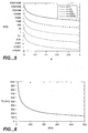
- a graphical illustration as shown in Fig. 5 may be generated and with Equation 4, a graphical illustration as shown in Fig. 6 may be generated for each particular sample.
- the graphical representations may be used to interpolate desired first and second rates of rotation and corresponding time intervals. For example, in a sample rotating in a container at 100 RPM and having a fluid density of 1030 kg/m 3 , a cell density of 1060 kg/m 3 , and a nominal value for cell diameter of 10 ⁇ m, a second rate of angular velocity ⁇ can be calculated as follows.
- Equation 5 is depicted in Fig. 5 in graphical form where n multiple curves of settling velocity are shown as a function of RPM and fraction change of rotational speed ⁇ .
- the second rate of rotation can be determined for this particular sample.
- the corresponding fraction change in rotational speed ⁇ may be interpolated or determined from the graph.
- the vertical velocity (Eq. 1) is at least 1000 times greater than that of settling velocity when the container is rotating at 100 RPM
- Fig. 5 indicates that the fraction change in rotational speed ⁇ must be greater than or equal to a fraction change of approximately 0.155 or 16% when rounded up.
- a 16 RPM shift in angular velocity will provide the required agitation to achieve the desired secondary flow and to ensure that the vertical velocity is at least 1000 times greater than the settling velocity.
- the shift may involve either a decrease of 16 RPM resulting in a second angular velocity of 84 RPM or an increase of 16 RPM resulting in a second angular velocity of 116 RPM.
- the first rate of rotation for this particular sample may be 100 RPM for a first time interval of 7.63 seconds and the second rate of rotation may be 116 RPM for a second time interval of 7.5 seconds if the angular velocity is to be 1000 times greater than the settling velocity for this particular sample.
- the vertical velocity need not be at least 1000 times the settling velocity.
- the first rate of rotation be sufficient such that n is greater than or equal to 1 so that the particles remain suspended in the fluid and do not settle. Therefore, the time interval and the RPM may be rounded up or down to a value, or alternatively be a different value so long as solid body rotation or settling of the particles on the bottom surface is not caused. Accordingly, many values for rates of rotation and time intervals may be used to maintain suspension of the particles.
- the cycle of rotation may be repeated as desired to maintain continuous suspension of particles and to prevent any particles from settling.
- the particles within the sample of the container may have settled out before the rotation cycle of the present invention begins or may be in solid body rotation. If the sample has settled out, the cycle of rotation of the present invention will first disperse particles as long as n is greater than or equal to 1. The greater the value of n, the quicker the particles will disperse.
- depth L of sample fluid in the container may be said to be fixed between sample runs to allow for ease in calculation. In reality, depth L decreases slightly as sample is aspirated from the sample tube. However, this flow entails a very small volume.
- the equations of the invention allow for exact calculation but the system of the present invention may have default numbers that work well for many various samples at many various fluid levels.
Landscapes
- Chemical & Material Sciences (AREA)
- Chemical Kinetics & Catalysis (AREA)
- Automatic Analysis And Handling Materials Therefor (AREA)
Applications Claiming Priority (2)
| Application Number | Priority Date | Filing Date | Title |
|---|---|---|---|
| US216481 | 2002-08-08 | ||
| US10/216,481 US20040027914A1 (en) | 2002-08-08 | 2002-08-08 | Method and system for maintaining particles in suspension in a fluid |
Publications (2)
| Publication Number | Publication Date |
|---|---|
| EP1388366A2 true EP1388366A2 (de) | 2004-02-11 |
| EP1388366A3 EP1388366A3 (de) | 2004-05-12 |
Family
ID=30443758
Family Applications (1)
| Application Number | Title | Priority Date | Filing Date |
|---|---|---|---|
| EP03016773A Withdrawn EP1388366A3 (de) | 2002-08-08 | 2003-07-23 | Verfahren und Vorrichtung zur Erhaltung von Teilchen in einer Flüssigkeitssuspension |
Country Status (3)
| Country | Link |
|---|---|
| US (1) | US20040027914A1 (de) |
| EP (1) | EP1388366A3 (de) |
| JP (1) | JP2004069700A (de) |
Cited By (1)
| Publication number | Priority date | Publication date | Assignee | Title |
|---|---|---|---|---|
| WO2007005973A3 (en) * | 2005-07-01 | 2007-06-14 | Honeywell Int Inc | A microfluidic card for rbc analysis |
Families Citing this family (13)
| Publication number | Priority date | Publication date | Assignee | Title |
|---|---|---|---|---|
| US7610942B2 (en) * | 2003-01-15 | 2009-11-03 | Amnis Corporation | Cell suspension rotating fluidic pump |
| US20100159498A1 (en) * | 2008-12-19 | 2010-06-24 | Ritzen Kalle | Blood analyzer with a blood cell sedimentation control mechanism and method of use |
| WO2011090605A2 (en) * | 2009-12-29 | 2011-07-28 | Caridianbct, Inc. | Method of loading and distributing cells in a bioreactor of a cell expansion system |
| EP3068866B1 (de) | 2013-11-16 | 2018-04-25 | Terumo BCT, Inc. | Zellenexpansion in einem bioreaktor |
| JP6783143B2 (ja) | 2014-03-25 | 2020-11-11 | テルモ ビーシーティー、インコーポレーテッド | 培地の受動的補充 |
| WO2017004592A1 (en) | 2015-07-02 | 2017-01-05 | Terumo Bct, Inc. | Cell growth with mechanical stimuli |
| WO2017058241A1 (en) | 2015-10-02 | 2017-04-06 | Hewlett Packard Development Company, L.P. | Rotating a printhead relative to vertical |
| CN109415696A (zh) | 2016-05-25 | 2019-03-01 | 泰尔茂比司特公司 | 细胞扩增 |
| US11104874B2 (en) | 2016-06-07 | 2021-08-31 | Terumo Bct, Inc. | Coating a bioreactor |
| US11685883B2 (en) | 2016-06-07 | 2023-06-27 | Terumo Bct, Inc. | Methods and systems for coating a cell growth surface |
| US10436697B2 (en) | 2016-11-19 | 2019-10-08 | Cytek Biosciences, Inc. | Flow cytometery system with fluidics control system |
| CN113510015A (zh) * | 2021-07-29 | 2021-10-19 | 厦门大学 | 一种新型微纳喷头 |
| CN220163241U (zh) * | 2023-04-26 | 2023-12-12 | 清源泰硕(北京)生物医疗科技有限公司 | 一种3d打印装置 |
Family Cites Families (4)
| Publication number | Priority date | Publication date | Assignee | Title |
|---|---|---|---|---|
| US3542344A (en) * | 1969-07-09 | 1970-11-24 | Dynatech Corp | Method and apparatus for mixing flowable materials in closed containers |
| US5005981A (en) * | 1989-09-08 | 1991-04-09 | Becton, Dickinson And Company | Apparatus for method for causing vortices in a test tube |
| ES2106023T3 (es) * | 1989-12-22 | 1997-11-01 | Alfa Biotech Spa | Aparato para la agitacion selectiva de componentes de reaccion. |
| US5840253A (en) * | 1996-06-20 | 1998-11-24 | Cytek Development Inc | Cell wash apparatus |
-
2002
- 2002-08-08 US US10/216,481 patent/US20040027914A1/en not_active Abandoned
-
2003
- 2003-07-23 EP EP03016773A patent/EP1388366A3/de not_active Withdrawn
- 2003-07-29 JP JP2003282194A patent/JP2004069700A/ja active Pending
Cited By (2)
| Publication number | Priority date | Publication date | Assignee | Title |
|---|---|---|---|---|
| WO2007005973A3 (en) * | 2005-07-01 | 2007-06-14 | Honeywell Int Inc | A microfluidic card for rbc analysis |
| US8034296B2 (en) | 2005-07-01 | 2011-10-11 | Honeywell International Inc. | Microfluidic card for RBC analysis |
Also Published As
| Publication number | Publication date |
|---|---|
| JP2004069700A (ja) | 2004-03-04 |
| EP1388366A3 (de) | 2004-05-12 |
| US20040027914A1 (en) | 2004-02-12 |
Similar Documents
| Publication | Publication Date | Title |
|---|---|---|
| EP1388366A2 (de) | Verfahren und Vorrichtung zur Erhaltung von Teilchen in einer Flüssigkeitssuspension | |
| JPH0546259B2 (de) | ||
| US4973165A (en) | Method of generating precisely-defined wall shearing stresses | |
| JP3411111B2 (ja) | 試料攪拌装置及び試料吸引装置 | |
| KR101587975B1 (ko) | 자동 세포 도말 시스템 및 그 제어방법 | |
| JP3847348B2 (ja) | 細胞洗浄装置及び方法 | |
| JP4600592B2 (ja) | 遠心分離器及び遠心分離方法 | |
| CN216224451U (zh) | 一种不对称振动微液滴生成机构 | |
| US7748893B2 (en) | Magnetic stirring arrangement | |
| JP3381925B2 (ja) | 容器内部の洗浄装置 | |
| CN114890572B (zh) | 一种化工废水处理工艺 | |
| CN109716142A (zh) | 自动分析装置 | |
| CN116086878A (zh) | 一种水质监测取水设备及其使用方法 | |
| CN1083746A (zh) | 具有离心分离器的连续式表面处理方法和设备 | |
| KR20220040239A (ko) | 오토 샘플링 장치 및 방법 | |
| CN111299244B (zh) | 一种多相混流清洗装置及其清洗工艺 | |
| CN212069749U (zh) | 一种多相混流清洗装置 | |
| EP0704244A2 (de) | Verfahren und Vorrichtung zum Speichern und Mischen von mehreren Flüssigkeiten, sowie Kassette zur Abnahme von Körperflüssigkeiten unter deren Verwendung | |
| JP2001310285A (ja) | チューブ搬送装置 | |
| US6202855B1 (en) | Process for the selection of particles of a preselected size from a particulate pharmaceutical product | |
| CN113447563A (zh) | 一种用于轮轴探伤的磁粉探伤机 | |
| JP5683595B2 (ja) | 不均一な溶液を均一溶液に混合する方法及び装置 | |
| JP2026026662A (ja) | 分注システム及び分注方法 | |
| JP2010115143A (ja) | 遠心分離装置 | |
| JPH04240080A (ja) | ロボット装置 |
Legal Events
| Date | Code | Title | Description |
|---|---|---|---|
| PUAI | Public reference made under article 153(3) epc to a published international application that has entered the european phase |
Free format text: ORIGINAL CODE: 0009012 |
|
| AK | Designated contracting states |
Kind code of ref document: A2 Designated state(s): AT BE BG CH CY CZ DE DK EE ES FI FR GB GR HU IE IT LI LU MC NL PT RO SE SI SK TR |
|
| AX | Request for extension of the european patent |
Extension state: AL LT LV MK |
|
| PUAL | Search report despatched |
Free format text: ORIGINAL CODE: 0009013 |
|
| AK | Designated contracting states |
Kind code of ref document: A3 Designated state(s): AT BE BG CH CY CZ DE DK EE ES FI FR GB GR HU IE IT LI LU MC NL PT RO SE SI SK TR |
|
| AX | Request for extension of the european patent |
Extension state: AL LT LV MK |
|
| AKX | Designation fees paid | ||
| REG | Reference to a national code |
Ref country code: DE Ref legal event code: 8566 |
|
| STAA | Information on the status of an ep patent application or granted ep patent |
Free format text: STATUS: THE APPLICATION IS DEEMED TO BE WITHDRAWN |
|
| 18D | Application deemed to be withdrawn |
Effective date: 20041113 |