EP1387708B1 - Automatic-lung regulator for compressed-air respiration apparatus - Google Patents
Automatic-lung regulator for compressed-air respiration apparatus Download PDFInfo
- Publication number
- EP1387708B1 EP1387708B1 EP02719678A EP02719678A EP1387708B1 EP 1387708 B1 EP1387708 B1 EP 1387708B1 EP 02719678 A EP02719678 A EP 02719678A EP 02719678 A EP02719678 A EP 02719678A EP 1387708 B1 EP1387708 B1 EP 1387708B1
- Authority
- EP
- European Patent Office
- Prior art keywords
- automatic
- compressed
- regulator
- respiration apparatus
- lung
- Prior art date
- Legal status (The legal status is an assumption and is not a legal conclusion. Google has not performed a legal analysis and makes no representation as to the accuracy of the status listed.)
- Expired - Lifetime
Links
Images

Classifications
-
- A—HUMAN NECESSITIES
- A62—LIFE-SAVING; FIRE-FIGHTING
- A62B—DEVICES, APPARATUS OR METHODS FOR LIFE-SAVING
- A62B31/00—Containers or portable cabins for affording breathing protection with devices for reconditioning the breathing air or for ventilating, in particular those that are suitable for invalids or small children
Definitions
- the invention relates to a regulator for SCBA, with a loaded to achieve an overpressure by a compression spring and operated by breathing membrane for controlling a valve for the air supply and a shut-off lever for locking the membrane in a break.
- Regulators of this type have long been known. They are connected between the pressure reducing valve of a Preß Kunststoffreservoirs and the respirator of a user and serve to provide a certain amount of breathing air with a suitable pressure for the human body.
- the actuation of the valve for releasing the air supply from the pressure reducer to the regulator is carried out by means of a control membrane moved by the user when inhaled due to the generated negative pressure.
- a control membrane moved by the user when inhaled due to the generated negative pressure.
- the known over-pressure regulators equipped with a manually operable locking mechanism, in which the control membrane entgenes End engages the membrane and holds it in the upper position, while the opposite end is locked in the groove of a leaf spring.
- the state of the art refers to a lung-controlled valve for a compressed-air breathing apparatus known from US-A-4572176 in which the regulation of the breathing gas supply takes place via an inlet valve connected to the respiratory gas source, which is actuated via a control lever with a push rod from a respirator operated by the respiration Control diaphragm is controlled.
- the control diaphragm can be kept depressurized in a blocking position with simultaneous closing of the intake valve.
- the invention is therefore based on the object in a pulmonary automaton of the type mentioned the switching mechanism for locking and releasing the air supply in such a way that this is easily solved by the user's inhalation, but the locking position is securely maintained during an interruption in mechanical shocks ,
- the object is achieved with a designed according to the features of claim 1 pulmonary.
- the basic idea of the invention consists firstly in the arrangement of a first spring element which acts on the pivotable lever attachment molding with low friction.
- This spring element is able to securely fix the shut-off lever during operation of the regulator to a stop, and thus is not contrary to the free mobility of the membrane.
- a second spring element When manually moving the Absperrhebels in the locked position during a stoppage of the lever attachment molding is additionally locked with the support of the first spring element behind a second spring element.
- this second spring element is so movable in the longitudinal direction to a limited extent that it still covers the lever attachment molding in case of unavoidable vibrations of the regulator during breaks in operation and this fixed even better.
- the second spring element is moved upwards again during inhalation through the molded body without appreciable resistance. Thereafter, the spring forces acting on the molding body of the first and second spring element can be easily overcome by the inhalation.
- the proposed switching mechanism ensures a safe shut-off the air supply during breaks, since the locking lever located in the blocking position can not be released by acting on the regulator lung blows. The unwanted outflow of air is thereby excluded.
- the second spring element can be easily moved through the molding and then to overcome the final release of the Absperrhebels only small spring forces are. In the operating position of the shut-off lever is also securely fixed by the first spring element.
- the first spring element is a longitudinally loaded leaf spring, which is supported on its narrow end faces in a groove of the lever attachment molding and in a groove on a fixed part of the regulator with low friction.
- the second spring element (safety mount) comprises a movably guided slide rail, which has a detent spring element on the side of the lever attachment molding.
- the detent spring element consists of an approximately semicircular receiving part for covering the lever attachment molding and a slope for lifting the second spring element when switching to the blocking position.
- a stop angle is provided at the other end of the slide to limit the longitudinal movement of the second spring element (safety bracket) in both directions.
- the lever attachment molding in the locking area with the detent spring element on a rounded sliding surface in order to move easily by its rotational movement along the slope or in the receiving part, the second spring element.
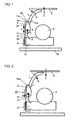
- the switching mechanism comprises a pivotally mounted shut-off lever 1, in the upper, for example in Fig. 1 position shown a stop for an under constant action a pressure spring (not shown) standing, with a formed by the respiration actuated membrane (not shown) connected membrane plate 2.
- This membrane plate 2 is connected via a lever system (not shown) with a closing mechanism for a valve 3, via which the air supply from a compressed air reservoir with pressure reducer (not shown) is released or locked.
- the shut-off lever 1 is constantly in the lower position shown in FIG. 3 and is resiliently held under the action of a leaf spring 4 on a stop formed by the valve 3.
- the diaphragm plate 2 can move downward (in the direction of the stopper lever 1 held at the valve stopper).
- the membrane plate 2 connected to the membrane is pushed up again and the valve 3 is closed, so that the desired overpressure in the regulator is maintained by the overpressure spring acting on the membrane plate 2 from above.
- the Absperrhebel 1 is connected to a lever attachment molding 5, which is pivotally mounted in a pivot.
- the molded body 5 is used in cooperation with the locking spring 4 to hold the shut-off lever 1 either in the lower position, ie in the operating position, or to fix in the upper position in which the air supply is completely blocked.
- the leaf spring 4 has a central bulge 4a and is held under spring tension at its two end edges in a wedge-shaped groove 7 of the lever attachment molding 5 or in a wedge-shaped groove 8 of a guide member 9 and stored.
- This design and arrangement of the locking spring 4 ensures a low-friction movement of Absperrhebels 1, so that when commissioning the regulator from the locked position only insignificant Counter forces are overcome and the shut-off lever 1 by merely breathing in the under position, ie the operating position is moved.
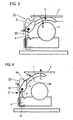
- the decommissioning of the regulator ie the interruption of any air supply, is achieved by means of an attached to the housing of the regulator lung pressure button, which is indicated in Fig. 4 by the arrow F.
- the molded body 5 Upon actuation of the push button, the molded body 5 is brought into the illustrated in Fig. 1, substantially vertical position and held in this position on the one hand by the leaf spring 4 and additionally by the safety bracket 10.
- a safety bracket 10 is provided.
- This safety bracket 10 includes a slide rail 11, a provided at the lower end of the slide rail 11 angle 12 and an upper end of the slide 11 angled detent spring element 13.
- the slide rail 11 is guided at a distance from the pivot 6 of the lever attachment molding 5 in the guide member 9 and according to the Distance between the guide member 9 and a stop 14 formed by the housing of the lung machine according to the arrow A movable.
- the detent spring element 13 is formed by an adjoining the slide rail 11, approximately semicircular arched receiving part 13a and one of the end obliquely upwardly projecting slope 13b.
- the shut-off lever 1 is fixed in the locking position both by the leaf spring 4 and by the safety bracket 10.
- the Absperrhebel 1 but can not adjust automatically as a result of shock generated by impact, as in this case, the safety bracket 10 slides down to the stop due to their own weight and the lever attachment molding 5 is locked even more secure in the receiving part 13a.
- the regulator can be brought back into operation by simply breathing, as pushed by the pressure acting on the membrane plate 2, the safety bracket 10 slightly up to the stop of the stop bracket 12 to the guide member 9 upwards and then the spring force of the detent spring element 13 and the leaf spring 4 is overcome.
- the switching mechanism described above ensures the safe shut-off of the air supply, so that no air can be lost from the compressed air reservoir. Nevertheless, however, an immediate recommissioning of the breathing apparatus connected to the respiratory protective device is possible because with the proposed switching mechanism, the forces acting to hold the shut-off lever can be overcome by merely breathing. In the operating position, the shut-off lever 1 is also securely held in a lower stop position.
- the shut-off lever 1 according to the arrow B upwards - in the blocking position - moves and acts (arrow C) on the membrane plate 2.
- the safety bracket 10 is located in the limited by the stop bracket 12 upper position.
- Fig. 3 shows the switching mechanism in the operating position in which the shut-off lever 1 by means of the leaf spring 4 is fixedly held on a stop (not shown) and actuated by the inhalation membrane plate 2 for opening and closing the valve 3 for the air supply to User can freely move up and down.
- Fig. 4 is finally the decommissioning of the regulator.
- the shut-off lever (1) by means of the push button (arrow F) is moved in the direction of arrow B and the safety bracket 10 by the movement of the lever attachment molding 5 along the slope 13b in the direction of arrow A is moved up to the stop angle 12 to the guide element strikes.
- the lever attachment molding 5 Upon further action on the push button (arrow F), the lever attachment molding 5 enters the position shown in Fig. 1, and overcoming the spring force of the detent spring element 13.
- the rigid slide rail 11 is laterally supported (not shown) and can in the upper area do not move laterally at a force acting on the detent spring element.
- Fig. 5 shows the commissioning of the regulator, in which by the user's breath and thereby caused pressure of the membrane plate 2 according to arrow C in the direction of arrow B moving shut-off lever 1, the safety bracket 10 is raised to the stop on the guide member 5 and then the spring force of the detent spring element 13 and the leaf spring 4 can be easily overcome.
Landscapes
- Health & Medical Sciences (AREA)
- Pulmonology (AREA)
- General Health & Medical Sciences (AREA)
- Business, Economics & Management (AREA)
- Emergency Management (AREA)
- Respiratory Apparatuses And Protective Means (AREA)
Description
Die Erfindung betrifft einen Lungenautomat für Pressluftatemgeräte, mit einer zur Erzielung eines Überdrucks durch eine Druckfeder belasteten und durch die Atmung betätigten Membran zur Steuerung eines Ventils für die Luftzufuhr sowie einen Absperrhebel zum Arretieren der Membran in einer Betriebspause.The invention relates to a regulator for SCBA, with a loaded to achieve an overpressure by a compression spring and operated by breathing membrane for controlling a valve for the air supply and a shut-off lever for locking the membrane in a break.
Lungenautomaten dieser Art sind seit langem bekannt. Sie sind zwischen das Druckreduzierventil eines Preßluftreservoirs und die Atemschutzmaske eines Benutzers geschaltet und dienen der Bereitstellung einer bestimmten Atemluftmenge mit einem für den menschlichen Organismus geeigneten Druck. Die Betätigung des Ventils zur Freigabe der Luftzufuhr vom Druckminderer in den Lungenautomat erfolgt mit Hilfe einer beim Einatmen durch den Benutzer aufgrund des erzeugten Unterdrucks bewegten Steuermembran. Bei der Überdruckvariante eines Lungenautomaten wird unter der Wirkung eine auf die gegenüberliegende Membranfläche ausgeübten Federkraft ein ständiger leichter Überdruck im Lungenautomaten geschaffen.Regulators of this type have long been known. They are connected between the pressure reducing valve of a Preßluftreservoirs and the respirator of a user and serve to provide a certain amount of breathing air with a suitable pressure for the human body. The actuation of the valve for releasing the air supply from the pressure reducer to the regulator is carried out by means of a control membrane moved by the user when inhaled due to the generated negative pressure. In the overpressure variant of an automatic regulator, under the action of a spring force exerted on the opposite membrane surface, a constant slight overpressure is created in the regulator.
Um bei einem Überdruck-Lungenautomaten das weitere Abströmen von Luft nach dessen Lösen von der Atemschutzmaske bzw. nach Abnehmen der Atemschutzmaske vom Kopf des Benutzers zu verhindern oder damit nach dem Anschließen an eine Druckluftversorgung nicht sofort Luft frei abströmen kann, sind die bekannten Überdruck-Lungenautomaten mit einem manuell betätigbaren Sperrmechanismus ausgestattet, bei dem die Steuermembran entgenes Ende an der Membran angreift und diese in der oberen Lage hält, während das gegenüberliegende Ende in der Nut einer Blattfeder verrastet ist. Wenn über das Pressluftatemgerät nach dem Anlegen der Atemschutzmaske bzw. dem Anschließen des Lungenautomaten dem Benutzer wieder Luft zugeführt werden soll, bewirkt bereits der durch das Anatmen erzeugte Unterdruck und die dabei durch die Steuermembran auf den Arretierhebel ausgeübte Kraft, dass das andere Hebelende aus der Federrast gelöst wird und der Lungenautomat wieder betriebsfähig ist. Dem angestrebten, bereits durch das Einatmen bewirkten leichten Freigeben des Arretierhebels steht jedoch der Nachteil entgegen, dass sich der Arretierhebel ebenso leicht durch mechanische Einwirkung auf den Lungenautomaten löst, so dass in von dem Benutzer gelöster Lage des Lungenautomaten unkontrolliert Pressluft ausströmen kann und bei der erneuten Benutzung des Pressluftatemgerätes nicht zur Verfügung steht.In order to prevent the further outflow of air after its release from the respirator or after removing the respirator from the user's head in an over-pressure respirator or thus can not immediately exhale air after connecting to a compressed air supply, the known over-pressure regulators equipped with a manually operable locking mechanism, in which the control membrane entgenes End engages the membrane and holds it in the upper position, while the opposite end is locked in the groove of a leaf spring. If the user is to be supplied with air again via the SCBA after the breathing mask has been put on or the regulator has been connected, the negative pressure already generated by the ana-breathing and the force exerted on the locking lever by the control diaphragm causes the other end of the lever to spring out of the spring catch is released and the regulator is operational again. The aspired, already caused by inhaling easy release of the locking lever, however, the disadvantage that the locking lever just as easily by mechanical action on the regulator solves, so that uncontrolled in the user dissolved position of the regulator can exude compressed air and at the renewed Use of the compressed air respirator is not available.
Zum Stand der Technik wird nach auf ein aus der US-A-4572176 bekannten lungengesteuertes Ventil für ein Pressluftatemgerät hingewiesen, bei dem die Regelung der Atemgasversorgung über ein mit der Atemgasquelle verbundenes Einlassventil erfolgt, das über einen Steuerhebel mit Schubstange von einer durch die Atmung betätigten Steuermembran gesteuert wird. Die Steuermembran kann unter gleichzeitigem Schließen des Einlassventils druckentlastet in einer Sperrstellung gehalten werden.The state of the art refers to a lung-controlled valve for a compressed-air breathing apparatus known from US-A-4572176 in which the regulation of the breathing gas supply takes place via an inlet valve connected to the respiratory gas source, which is actuated via a control lever with a push rod from a respirator operated by the respiration Control diaphragm is controlled. The control diaphragm can be kept depressurized in a blocking position with simultaneous closing of the intake valve.
Der Erfindung liegt daher die Aufgabe zugrunde, bei einem Lungenautomaten der eingangs erwähnten Art den Umschaltmechanismus zum Sperren und Freigeben der Luftzufuhr so auszubilden, dass dieser zwar leicht durch das Einatmen des Benutzers gelöst wird, aber die Verriegelungsposition während einer Betriebsunterbrechung bei mechanischen Erschütterungen sicher beibehalten wird.The invention is therefore based on the object in a pulmonary automaton of the type mentioned the switching mechanism for locking and releasing the air supply in such a way that this is easily solved by the user's inhalation, but the locking position is securely maintained during an interruption in mechanical shocks ,
Erfindungsgemäß wird die Aufgabe mit einem gemäß den Merkmalen des Patentanspruches 1 ausgebildeten Lungenautomaten gelöst.According to the invention the object is achieved with a designed according to the features of
Der Grundgedanke der Erfindung besteht mit anderen Worten zum einen in der Anordnung eines mit geringer Reibung an dem schwenkbaren Hebelbefestigungsformkörper angreifenden ersten Federelement. Dieses Federelement ist in der Lage, den Absperrhebel während des Betriebes des Lungenautomaten an einem Anschlag sicher zu fixieren, und steht damit der freien Beweglichkeit der Membran nicht entgegen. Beim manuellen Umlegen des Absperrhebels in die Sperrposition während einer Betriebsunterbrechung wird der Hebelbefestigungsformkörper mit Unterstützung des ersten Federelements hinter einem zweiten Federelement zusätzlich verrastet. Dieses zweite Federelement ist jedoch in Längsrichtung in begrenztem Maße so beweglich, dass es sich bei in Betriebspausen unvermeidlichen Erschütterungen des Lungenautomaten den Hebelbefestigungsformkörper noch weiter überdeckt und diesen noch besser fixiert. Bei der erwähnten Inbetriebnahme des Lungenautomaten wird das zweite Federelement beim Einatmen durch den Formkörper ohne merklichen Widerstand wieder nach oben bewegt. Danach können die auf den Formkörper wirkenden Federkräfte des ersten und zweiten Federelements durch das Einatmen leicht überwunden werden.In other words, the basic idea of the invention consists firstly in the arrangement of a first spring element which acts on the pivotable lever attachment molding with low friction. This spring element is able to securely fix the shut-off lever during operation of the regulator to a stop, and thus is not contrary to the free mobility of the membrane. When manually moving the Absperrhebels in the locked position during a stoppage of the lever attachment molding is additionally locked with the support of the first spring element behind a second spring element. However, this second spring element is so movable in the longitudinal direction to a limited extent that it still covers the lever attachment molding in case of unavoidable vibrations of the regulator during breaks in operation and this fixed even better. In the mentioned start-up of the regulator, the second spring element is moved upwards again during inhalation through the molded body without appreciable resistance. Thereafter, the spring forces acting on the molding body of the first and second spring element can be easily overcome by the inhalation.
Der vorgeschlagene Umschaltmechanismus gewährleistet bei Betriebspausen ein sicheres Sperren der Luftzufuhr, da der in Sperrstellung befindliche Absperrhebel auch durch auf den Lungenautomaten wirkende Schläge nicht freigegeben werden kann. Das ungewollte Abströmen von Luft ist dadurch ausgeschlossen. Trotz der sicheren Verriegelung kann der Sperrhebel aber durch bloßes Anatmen sofort wieder in die Betriebsstellung gebracht werden, da das zweite Federelement durch den Formkörper leicht verschoben werden kann und dann zur endgültigen Freigabe des Absperrhebels nur noch geringe Federkräfte zu überwinden sind. In der Betriebsstellung ist der Absperrhebel durch das erste Federelement ebenfalls sicher fixiert.The proposed switching mechanism ensures a safe shut-off the air supply during breaks, since the locking lever located in the blocking position can not be released by acting on the regulator lung blows. The unwanted outflow of air is thereby excluded. Despite the secure locking of the locking lever but can be brought back into the operating position by just breathe immediately, because the second spring element can be easily moved through the molding and then to overcome the final release of the Absperrhebels only small spring forces are. In the operating position of the shut-off lever is also securely fixed by the first spring element.
In Ausgestaltung der Erfindung ist das erste Federelement eine in Längsrichtung belastete Blattfeder, die an ihren schmalen Stirnseiten in einer Nut des Hebelbefestigungsformkörpers sowie in einer Nut an einem feststehenden Teil des Lungenautomaten reibungsarm abgestützt ist.In an embodiment of the invention, the first spring element is a longitudinally loaded leaf spring, which is supported on its narrow end faces in a groove of the lever attachment molding and in a groove on a fixed part of the regulator with low friction.
In weiterer Ausgestaltung der Erfindung umfasst das zweite Federelement (Sicherheitshalterung) eine beweglich geführte Gleitschiene, die an der Seite des Hebelbefestigungsformkörpers ein Rastfederelement aufweist. Das Rastfederelement besteht aus einem etwa halbkreisförmigen Aufnahmeteil zur Überdeckung des Hebelbefestigungsformkörpers und einer Schräge zum Anheben des zweiten Federelements beim Umschalten in die Sperrposition. Am anderen Ende der Gleitschiene ist ein Anschlagwinkel vorgesehen, um die Längsbewegung des zweiten Federelements (Sicherheitshalterung) in beiden Richtungen zu begrenzen.In a further embodiment of the invention, the second spring element (safety mount) comprises a movably guided slide rail, which has a detent spring element on the side of the lever attachment molding. The detent spring element consists of an approximately semicircular receiving part for covering the lever attachment molding and a slope for lifting the second spring element when switching to the blocking position. At the other end of the slide a stop angle is provided to limit the longitudinal movement of the second spring element (safety bracket) in both directions.
In weiterer Ausgestaltung der Erfindung weist der Hebelbefestigungsformkörper im Verriegelungsbereich mit dem Rastfederelement eine gerundete Gleitfläche auf, um durch seine Drehbewegung entlang der Schräge bzw. in dem Aufnahmeteil das zweite Federelement leicht bewegen zu können.In a further embodiment of the invention, the lever attachment molding in the locking area with the detent spring element on a rounded sliding surface in order to move easily by its rotational movement along the slope or in the receiving part, the second spring element.
Aus den Ansprüchen ergeben sich weitere Merkmale und vorteilhafte Weiterbildungen der Erfindung.From the claims, there are further features and advantageous developments of the invention.
Ein Ausführungsbeispiel der Erfindung wird anhand der Zeichnung näher erläutert. Die Figuren 1 bis 5 geben in einer schematischen Darstellung die verschiedenen Schaltpositionen eines Umschaltmechanismus für einen Überdruck-Lungenautomaten wieder.
- Fig. 1
- zeigt den Umschaltmechanismus in der manuell gesperrten, aber entlasteten Position;
- Fig. 2
- zeigt den Umschaltmechanismus nach Fig. 1 in einer nach einer Erschütterung durch Schlageinwirkung weiterhin für die Luftzufuhr gesperrten Position;
- Fig. 3
- zeigt den Umschaltmechanismus nach dem Anatmen und während des Betriebes;
- Fig. 4
- zeigt den Umschaltmechanismus beim Abschalten durch manuelle Betätigung;
- Fig. 5
- zeigt den Umschaltmechanismus beim Umschalten von der Sperrposition in die Atemposition.
- Fig. 1
- shows the switching mechanism in the manually locked but unloaded position;
- Fig. 2
- shows the switching mechanism of Figure 1 in a after a shock caused by impact still locked for the air supply position.
- Fig. 3
- shows the switching mechanism after inhalation and during operation;
- Fig. 4
- shows the switching mechanism at shutdown by manual operation;
- Fig. 5
- shows the switching mechanism when switching from the locked position to the breathing position.
Gemäß den Figuren 1 bis 5 umfaßt der Umschaltmechanismus einen schwenkbar gelagerten Absperrhebel 1, der in der oberen, beispielsweise in Fig. 1 dargestellten Position einen Anschlag für eine unter ständiger Wirkung eine Überdruckfeder (nicht dargestellt) stehende, mit einer durch die Atmung betätigten Membran (nicht dargestellt) verbundenen Membranplatte 2 bildet. Diese Membranplatte 2 ist über ein Hebelsystem (nicht dargestellt) mit einem Schließmechanismus für ein Ventil 3 verbunden, über das die Luftzufuhr aus einem Druckluftreservoir mit Druckminderer (nicht dargestellt) freigegeben oder gesperrt wird. Während der Benutzung eines Pressluft-Atemgerätes befindet sich der Absperrhebel 1 ständig in der in Fig. 3 dargestellten unteren Position und ist unter der Wirkung einer Blattfeder 4 an einem von dem Ventil 3 gebildeten Anschlag federnd gehalten. Somit kann sich die Membranplatte 2 unter der Wirkung des bei jedem Atemzug erzeugten Unterdruckes nach unten (in Richtung des am Ventilanschlag gehaltenen Absperrhebels 1) bewegen. Nach jedem Atemzug wird die mit der Membran verbundene Membranplatte 2 wieder nach oben gedrückt und das Ventil 3 geschlossen, so dass der gewünschte Überdruck in dem Lungenautomat durch die von oben auf die Membranplatte 2 wirkende Überdruckfeder aufrechterhalten wird.According to Figures 1 to 5, the switching mechanism comprises a pivotally mounted shut-
Der Absperrhebel 1 ist mit einem Hebelbefestigungsformkörper 5 verbunden, der in einem Drehgelenk.6 schwenkbar gelagert ist. Der Formkörper 5 dient im Zusammenwirken mit der Sperrfeder 4 dazu, den Absperrhebel 1 entweder in der unteren Position, d.h. in der Betriebsposition, zu halten oder in der oberen Position, in der die Luftzufuhr vollständig gesperrt ist, zu fixieren. Die Blattfeder 4 weist eine mittige Ausbauchung 4a auf und ist unter Federspannung an ihren beiden stirnseitigen Kanten in einer keilförmigen Nut 7 des Hebelbefestigungsformkörpers 5 bzw. in einer keilförmigen Nut 8 eines Führungselements 9 gehalten und gelagert. Diese Ausbildung und Anordnung der Sperrfeder 4 gewährleistet eine reibungsarme Bewegung des Absperrhebels 1, so dass bei der Inbetriebsetzung des Lungenautomaten aus der Sperrstellung nur unerhebliche Gegenkräfte zu überwinden sind und der Absperrhebel 1 durch bloßes Anatmen in die unter Position, d.h. die Betriebsstellung, bewegt wird. Die Außerbetriebsetzung des Lungenautomaten, d.h. die Unterbrechung jeglicher Luftzufuhr, wird mit Hilfe einer am Gehäuse des Lungenautomaten angebrachten Drucktaste, die in Fig. 4 mit dem Pfeil F angedeutet ist, erreicht. Bei Betätigung der Drucktaste wird der Formkörper 5 in die in Fig. 1 dargestellte, im wesentlichen senkrechte Lage gebracht und in dieser Position zum einen durch die Blattfeder 4 und zusätzlich durch die Sicherheitshalterung 10 gehalten.The Absperrhebel 1 is connected to a
Damit sich der Absperrhebel 1 aber nicht durch Erschütterungen selbsttätig in die untere Position, d.h. die Betriebsposition, bewegt, in der unter der Wirkung des auf die Membranplatte 2 wirkenden Federdruckes ständig Luft entweichen kann, ist zusätzlich zur Blattfeder 4 eine Sicherheitshalterung 10 vorgesehen. Diese Sicherheitshalterung 10 umfaßt eine Gleitschiene 11, einen am unteren Ende der Gleitschiene 11 vorgesehenen Anschlagwinkel 12 und eine am oberen Ende der Gleitschiene 11 abgewinkeltes Rastfederelement 13. Die Gleitschiene 11 ist im Abstand vom Drehgelenk 6 des Hebelbefestigungsformkörpers 5 in dem Führungselement 9 geführt und entsprechend dem Abstandsmaß zwischen dem Führungselement 9 und einen von dem Gehäuse des Lungenautomaten gebildeten Anschlag 14 gemäß dem Pfeil A beweglich. Das Rastfederelement 13 ist durch ein sich an die Gleitschiene 11 anschließendes, etwa halbkreisförmig gewölbtes Aufnahmeteil 13a und eine von dessen Ende schräg nach oben abstehende Schräge 13b gebildet.Thus, the
Bei Betätigung der Drucktaste (Pfeil F) zur Außerbetriebsetzung des Lungenautomaten gleitet das abgerundete Ende des Hebelbefestigungsformkörpers 5 zunächst entlang der Schräge 13a, so dass die Sicherheitshebelhalterung 10 in die obere Lage gelangt, in der der Anschlagwinkel 12 am Führungselement 9 anschlägt. Danach rutscht das abgerundete Formkörperende unter Überwindung der Federkraft des Rastfederelements 13 in das Aufnahmeteil 13a.By pressing the pushbutton (arrow F) to deactivate the regulator, the rounded end slides of the
Damit ist der Absperrhebel 1 in der Sperrposition sowohl durch die Blattfeder 4 als auch durch die Sicherheitshalterung 10 fixiert. Der Absperrhebel 1 kann sich aber auch infolge einer durch Schlageinwirkung erzeugten Erschütterung nicht selbsttätig verstellen, da in diesem Fall die Sicherheitshalterung 10 aufgrund ihres Eigengewichts bis zum Anschlag nach unten gleitet und der Hebelbefestigungsformkörper 5 noch sicherer in dem Aufnahmeteil 13a verriegelt ist. Trotz dieser sicheren Verriegelung des mit dem Absperrhebel 1 verbundenen Hebelbefestigungsformkörpers 5 kann der Lungenautomat durch bloßes Anatmen wieder in Betrieb gebracht werden, da durch den auf die Membranplatte 2 wirkenden Druck die Sicherheitshalterung 10 leicht bis zum Anschlag des Anschlagwinkels 12 an das Führungselement 9 nach oben verschoben und anschließend die Federkraft des Rastfederelements 13 sowie der Blattfeder 4 überwunden wird.Thus, the shut-off
Mit dem zuvor beschriebenen Umschaltmechanismus ist einerseits das sichere Absperren der Luftzufuhr gewährleistet, so dass keine Luft aus dem Pressluftreservoir verlorengehen kann. Dennoch ist aber eine sofortige Wiederinbetriebnahme des mit dem Atemschutzgerät verbundenen Lungenautomaten möglich, da mit dem vorgeschlagenen Umschaltmechanismus die zum Halten des Absperrhebels wirksamen Kräfte durch bloßes Anatmen überwunden werden können. In der Betriebsstellung ist der Absperrhebel 1 ebenfalls sicher in einer unteren Anschlagposition gehalten.With the switching mechanism described above, on the one hand ensures the safe shut-off of the air supply, so that no air can be lost from the compressed air reservoir. Nevertheless, however, an immediate recommissioning of the breathing apparatus connected to the respiratory protective device is possible because with the proposed switching mechanism, the forces acting to hold the shut-off lever can be overcome by merely breathing. In the operating position, the shut-off
Die Funktion des Umschaltmechanismus wird noch einmal anhand der in den Fig. 1 bis 5 wiedergegebenen Positionen erläutert.The function of the switching mechanism will be explained again with reference to the reproduced in FIGS. 1 to 5 positions.
Gemäß Fig. 1 wurde der Absperrhebel 1 gemäß dem Pfeil B nach oben - in die Sperrstellung - bewegt und wirkt (Pfeil C) auf die Membranplatte 2. Damit ist die Luftzufuhr gesperrt. Die Sicherheitshalterung 10 befindet sich in der durch den Anschlagwinkel 12 begrenzten oberen Position.According to Fig. 1, the shut-off
Bei einer Schlageinwirkung auf den Lungenautomaten, bei der sich - gemäß Fig. 2 - die Membranplatte 2 und der Absperrhebel 1 in Richtung der Pfeile C und B bewegen, wird diese unerwünschte, mit einem Luftverlust verbundenen Bewegung des Absperrhebels 1 und der Membranplatte 2 verhindert, indem die Sicherheitshalterung 10 nach unten fällt und somit der Hebelbefestigungsformkörper 5 vollständig in dem Aufnahmeteil 13a gehalten ist.In a blow on the regulator, in which - move as shown in FIG. 2 - the
Fig. 3 zeigt den Umschaltmechanismus in der Betriebsposition, in der der Absperrhebel 1 mit Hilfe der Blattfeder 4 fest an einen Anschlag (nicht dargestellt) gehalten ist und sich die durch das Einatmen betätigte Membranplatte 2 zum Öffnen und Schließen des Ventils 3 für die Luftzufuhr zum Benutzer frei aufwärts und abwärts bewegen kann.Fig. 3 shows the switching mechanism in the operating position in which the shut-off
Fig. 4 gibt schließlich die Außerbetriebsetzung des Lungenautomaten wieder. Dabei wird der Absperrhebel (1) mittels der Drucktaste (Pfeil F) in Richtung des Pfeils B bewegt und die Sicherheitshalterung 10 durch die Bewegung des Hebelbefestigungsformkörpers 5 entlang der Schräge 13b in Richtung des Pfeils A nach oben verschoben bis der Anschlagwinkel 12 an das Führungselement 9 anschlägt. Bei weiterer Einwirkung auf die Drucktaste (Pfeil F) gelangt der Hebelbefestigungsformkörper 5 in die in Fig. 1 dargestellte Position, und zwar unter Überwindung der Federkraft des Rastfederelements 13. Die biegesteife Gleitschiene 11 ist auch im oberen Bereich seitlich abgestützt (nicht dargestellt) und kann bei einer Kraftwirkung auf das Rastfederelement nicht seitlich ausweichen.Fig. 4 is finally the decommissioning of the regulator. In this case, the shut-off lever (1) by means of the push button (arrow F) is moved in the direction of arrow B and the
Fig. 5 zeigt die Inbetriebsetzung des Lungenautomaten, bei der durch das Anatmen des Benutzers und den dadurch bewirkten Druck der Membranplatte 2 gemäß Pfeil C auf den sich in Richtung des Pfeils B bewegenden Absperrhebel 1 die Sicherheitshalterung 10 bis zum Anschlag am Führungselement 5 angehoben und anschließend die Federkraft des Rastfederelements 13 und der Blattfeder 4 leicht überwunden werden kann.Fig. 5 shows the commissioning of the regulator, in which by the user's breath and thereby caused pressure of the
- 11
- Absperrhebelshutoff
- 22
- Membranplattediaphragm plate
- 33
- VentilValve
- 44
- Blattfeder (erstes Federelement)Leaf spring (first spring element)
- 4a4a
- Ausbauchung von 4Bulge of 4
- 55
- HebelbefestigungsformkörperMolded lever mounting
- 5a5a
- gerundete Gleitflächerounded sliding surface
- 66
- Drehgelenk von 5Swivel of 5
- 77
- keilförmige Nut von 5wedge-shaped groove of 5
- 88th
- keilförmige Nut von 9wedge-shaped groove of 9
- 99
- Führungselementguide element
- 1010
- Sicherheitshalterung (zweites Federelement)Safety bracket (second spring element)
- 1111
- Gleitschieneslide
- 1212
- AnschlagwinkelSquares
- 1313
- RastfederelementDetent spring element
- 13a13a
- Aufnahmeteilreceiving part
- 13b13b
- Schrägeslope
- 1414
-
Anschlag 14
Stop 14
- Pfeil FArrow F
- Drucktastepushbutton
- Pfeil AArrow A.
- Bewegung der SicherheitshalterungMovement of the safety bracket
- Pfeil BArrow B
- Bewegung des Absperrhebel / HebelbefestigungsformkörpersMovement of the shut-off lever / lever attachment molding
- Pfeil CArrow C
- Bewegung der MembranplatteMovement of the membrane plate
Claims (12)
- An automatic-lung regulator for compressed-air respiration apparatus with a respiration-operated and spring-loaded membrane (2) to create positive pressure for controlling an air supply valve and a locking lever (1) for locking the membrane (2) in periods of non-operation, characterized in
that the locking lever (1) is connected to a pivoted molded lever mounting piece (5) that is kept both in the release position and in the blocking position of the membrane (2) by a low-friction spring mounting (4) and to which as a safety holding device (10) is provided a second catch spring element (13) whose movement is limited in its longitudinal direction, by which the molded lever mounting device (5) can additionally be spring-locked in the blocking position and which in the event of an impact is moving vertically according to its own weight to encompass the molded lever mounting device (5) even more. - The automatic-lung regulator for compressed-air respiration apparatus according to claim 1, characterized in that a leaf spring (4) charged in longitudinal direction is provided to create the first spring force that acts on the molded lever mounting piece (5).
- The automatic-lung regulator for compressed-air respiration apparatus according to claim 2, characterized in that the leaf spring (4) is flexibly supported on its narrow front sides in grooves (7) and (8) that are located in the molded lever mounting piece (5) or a static part (9) of the valve body, respectively.
- The automatic-lung regulator for compressed-air respiration apparatus according to claim 3, characterized in that the grooves (7, 8) are arranged slantingly.
- The automatic-lung regulator for compressed-air respiration apparatus according to claims 3 and 4, characterized in that the grooves (7, 8) are wedge-shaped.
- The automatic-lung regulator for compressed-air respiration apparatus according to any one of the claims 1 through 5, characterized in that the molded lever mounting piece (5) comprises a rounded sliding surface (5a) on the side opposite the groove (7).
- The automatic-lung regulator for compressed-air respiration apparatus according to any one of the claims 1 through 6, characterized in that the molded lever mounting piece (5) sits in a hinged joint (6) and comprises a pushbutton (arrow F) for manually swiveling the locking lever (1) into its locking position on the side facing away from the locking lever (1) and under the hinged joint (6).
- The automatic-lung regulator for compressed-air respiration apparatus according to claim 1, characterized in that the safety holding device (10) is a slide bar (11) guided in a guide (9) that turns into a catch spring element (13) consisting of an approximately semicircular receiving part (13a) and an adjacent slope (13b) on the end where the molded lever mounting piece (5) is located and that comprises a back square (12) for limiting the longitudinal movement of the safety holding device (10) in both directions on the opposite end.
- The automatic-lung regulator for compressed-air respiration apparatus according to claim 8, characterized in that the safety holding device (10) is molded from spring band steel that is braced by a reinforcing crease in the section of the guided slide bar (11).
- The automatic-lung regulator for compressed-air respiration apparatus according to claims 8 and 9, characterized in that the safety holding device (10) is supported in the slide bar (11) section on the casing of the automatic-lung regulator on the side opposite the molded lever mounting piece (5).
- The automatic-lung regulator for compressed-air respiration apparatus according to claims 8 through 10, characterized in that, in the locking position of the locking lever (1), the molded lever mounting piece (5) is at first partially and, in the event of vibrations of the automatic-lung regulator, even further encompassed by the receiving part (13a) of the catch spring element (13) as the safety holding device (10) sinks into it by gravitation.
- The automatic-lung regulator for compressed-air respiration apparatus according to any one of claims 1 through 11, characterized in that the locking lever (1) is either angular or curved in a section distant from the molded lever mounting piece (5).
Applications Claiming Priority (3)
| Application Number | Priority Date | Filing Date | Title |
|---|---|---|---|
| DE10125076 | 2001-05-14 | ||
| DE2001125076 DE10125076C1 (en) | 2001-05-14 | 2001-05-14 | Automatic lung, for pressurized air respiration device, has blocking lever for securing membrane in operating pause provided with safety restraint preventing release by mechanical shock |
| PCT/DE2002/000920 WO2002092155A1 (en) | 2001-05-14 | 2002-03-12 | Automatic-lung regulator for compressed-air respiration apparatus |
Publications (3)
| Publication Number | Publication Date |
|---|---|
| EP1387708A1 EP1387708A1 (en) | 2004-02-11 |
| EP1387708B1 true EP1387708B1 (en) | 2007-01-17 |
| EP1387708B9 EP1387708B9 (en) | 2007-10-24 |
Family
ID=7685817
Family Applications (1)
| Application Number | Title | Priority Date | Filing Date |
|---|---|---|---|
| EP02719678A Expired - Lifetime EP1387708B9 (en) | 2001-05-14 | 2002-03-12 | Automatic-lung regulator for compressed-air respiration apparatus |
Country Status (5)
| Country | Link |
|---|---|
| EP (1) | EP1387708B9 (en) |
| AU (1) | AU2002250818B2 (en) |
| DE (2) | DE10125076C1 (en) |
| ES (1) | ES2278910T3 (en) |
| WO (1) | WO2002092155A1 (en) |
Cited By (1)
| Publication number | Priority date | Publication date | Assignee | Title |
|---|---|---|---|---|
| DE102019108790A1 (en) * | 2019-04-03 | 2020-10-08 | BartelsRieger Atemschutztechnik GmbH | Demand regulator, in particular for a breathing apparatus |
Families Citing this family (2)
| Publication number | Priority date | Publication date | Assignee | Title |
|---|---|---|---|---|
| DE202010018338U1 (en) | 2009-04-22 | 2015-10-12 | Nevro Corporation | Spinal cord modulation system for the relief of chronic pain |
| CN114602142B (en) * | 2022-02-25 | 2023-10-27 | 江苏康康同学科技有限公司 | Be used for patient's pulmonary function rehabilitation training device |
Family Cites Families (4)
| Publication number | Priority date | Publication date | Assignee | Title |
|---|---|---|---|---|
| US4284075A (en) * | 1978-06-17 | 1981-08-18 | Alan Krasberg | Diving headgear for use in return-line diving systems |
| FR2535612B1 (en) * | 1982-11-05 | 1986-04-11 | Lejeune Seitz Ameline Labo | IMPROVED BREATHING VALVE |
| IT1161849B (en) * | 1983-05-19 | 1987-03-18 | Sekur Spa | SWITCHING DEVICE FOR AN AIR DISPENSER INTENDED TO FEED BREATHABLE AIR WITHIN A BREATHING AIR |
| IT216049Z2 (en) * | 1988-12-29 | 1991-04-26 | Amf Mares Spa | AUTOMATIC DISPENSER FOR SELF-BREAKING RATORS |
-
2001
- 2001-05-14 DE DE2001125076 patent/DE10125076C1/en not_active Expired - Lifetime
-
2002
- 2002-03-12 EP EP02719678A patent/EP1387708B9/en not_active Expired - Lifetime
- 2002-03-12 ES ES02719678T patent/ES2278910T3/en not_active Expired - Lifetime
- 2002-03-12 WO PCT/DE2002/000920 patent/WO2002092155A1/en active IP Right Grant
- 2002-03-12 AU AU2002250818A patent/AU2002250818B2/en not_active Ceased
- 2002-03-12 DE DE50209289T patent/DE50209289D1/en not_active Expired - Fee Related
Cited By (2)
| Publication number | Priority date | Publication date | Assignee | Title |
|---|---|---|---|---|
| DE102019108790A1 (en) * | 2019-04-03 | 2020-10-08 | BartelsRieger Atemschutztechnik GmbH | Demand regulator, in particular for a breathing apparatus |
| DE102019108790B4 (en) * | 2019-04-03 | 2020-11-19 | BartelsRieger Atemschutztechnik GmbH | Demand regulator, in particular for a breathing apparatus |
Also Published As
| Publication number | Publication date |
|---|---|
| DE10125076C1 (en) | 2002-05-23 |
| DE50209289D1 (en) | 2007-03-08 |
| EP1387708A1 (en) | 2004-02-11 |
| AU2002250818B2 (en) | 2005-06-09 |
| EP1387708B9 (en) | 2007-10-24 |
| WO2002092155A1 (en) | 2002-11-21 |
| ES2278910T3 (en) | 2007-08-16 |
Similar Documents
| Publication | Publication Date | Title |
|---|---|---|
| DE2302110C3 (en) | Anesthesia machine | |
| CH624013A5 (en) | ||
| EP0111754A1 (en) | Respiratory apparatus for positive pressure ventilation | |
| DE2945472A1 (en) | NARCOSE VENTILATION SYSTEM WITH PNEUMATIC CONTROL | |
| DE1273132B (en) | Control device for ventilators | |
| EP1387708B1 (en) | Automatic-lung regulator for compressed-air respiration apparatus | |
| DE60208985T2 (en) | Ventilator with flow limiter | |
| DE1491668B1 (en) | Anesthesia device | |
| DE102019108790B4 (en) | Demand regulator, in particular for a breathing apparatus | |
| WO2004112529A1 (en) | Case in the form of a travel case | |
| DE974814C (en) | Diving device with a lung-controlled, nutrient gas supply fed by the high pressure container | |
| DE1141186B (en) | Breathing apparatus with breathing air circulation | |
| DE3033068C2 (en) | Oxygen rescue device, in particular for use in mines | |
| DE10040360B4 (en) | Pressure regulators, in particular for diving sports equipment | |
| DE548272C (en) | Pulmonary breathing apparatus | |
| DE2901985A1 (en) | Automatically starting oxygen respirator - has externally accessible impact mechanism connected to oxygen cylinder control valve | |
| DE6602445U (en) | REGULATING DEVICE FOR VENTILATION DEVICES | |
| DE1273134B (en) | Ventilator | |
| DE1506341C3 (en) | Breathing device for divers | |
| DE1027516B (en) | Lung-controlled breathing apparatus, especially high altitude breathing apparatus | |
| DE1159766B (en) | Breathing apparatus with breathing air circulation | |
| DE1491691C (en) | Ventilator, in particular for anesthesia ventilation | |
| DE2107129C3 (en) | Device for generating gas flows | |
| DE1153258B (en) | Compressed gas breathing apparatus with lung-controlled breathing gas supply valve | |
| DE3038128A1 (en) | BREATHING MASK |
Legal Events
| Date | Code | Title | Description |
|---|---|---|---|
| PUAI | Public reference made under article 153(3) epc to a published international application that has entered the european phase |
Free format text: ORIGINAL CODE: 0009012 |
|
| 17P | Request for examination filed |
Effective date: 20030916 |
|
| AK | Designated contracting states |
Kind code of ref document: A1 Designated state(s): AT BE CH CY DE DK ES FI FR GB GR IE IT LI LU MC NL PT SE TR |
|
| AX | Request for extension of the european patent |
Extension state: AL LT LV MK RO SI |
|
| GRAP | Despatch of communication of intention to grant a patent |
Free format text: ORIGINAL CODE: EPIDOSNIGR1 |
|
| GRAS | Grant fee paid |
Free format text: ORIGINAL CODE: EPIDOSNIGR3 |
|
| GRAA | (expected) grant |
Free format text: ORIGINAL CODE: 0009210 |
|
| AK | Designated contracting states |
Kind code of ref document: B1 Designated state(s): AT BE CH CY DE DK ES FI FR GB GR IE IT LI LU MC NL PT SE TR |
|
| PG25 | Lapsed in a contracting state [announced via postgrant information from national office to epo] |
Ref country code: FI Free format text: LAPSE BECAUSE OF FAILURE TO SUBMIT A TRANSLATION OF THE DESCRIPTION OR TO PAY THE FEE WITHIN THE PRESCRIBED TIME-LIMIT Effective date: 20070117 Ref country code: DK Free format text: LAPSE BECAUSE OF FAILURE TO SUBMIT A TRANSLATION OF THE DESCRIPTION OR TO PAY THE FEE WITHIN THE PRESCRIBED TIME-LIMIT Effective date: 20070117 Ref country code: IE Free format text: LAPSE BECAUSE OF FAILURE TO SUBMIT A TRANSLATION OF THE DESCRIPTION OR TO PAY THE FEE WITHIN THE PRESCRIBED TIME-LIMIT Effective date: 20070117 Ref country code: NL Free format text: LAPSE BECAUSE OF FAILURE TO SUBMIT A TRANSLATION OF THE DESCRIPTION OR TO PAY THE FEE WITHIN THE PRESCRIBED TIME-LIMIT Effective date: 20070117 |
|
| REG | Reference to a national code |
Ref country code: GB Ref legal event code: FG4D Free format text: NOT ENGLISH |
|
| REG | Reference to a national code |
Ref country code: CH Ref legal event code: EP |
|
| REG | Reference to a national code |
Ref country code: IE Ref legal event code: FG4D Free format text: LANGUAGE OF EP DOCUMENT: GERMAN |
|
| REF | Corresponds to: |
Ref document number: 50209289 Country of ref document: DE Date of ref document: 20070308 Kind code of ref document: P |
|
| GBT | Gb: translation of ep patent filed (gb section 77(6)(a)/1977) |
Effective date: 20070215 |
|
| PG25 | Lapsed in a contracting state [announced via postgrant information from national office to epo] |
Ref country code: SE Free format text: LAPSE BECAUSE OF FAILURE TO SUBMIT A TRANSLATION OF THE DESCRIPTION OR TO PAY THE FEE WITHIN THE PRESCRIBED TIME-LIMIT Effective date: 20070417 |
|
| PG25 | Lapsed in a contracting state [announced via postgrant information from national office to epo] |
Ref country code: PT Free format text: LAPSE BECAUSE OF FAILURE TO SUBMIT A TRANSLATION OF THE DESCRIPTION OR TO PAY THE FEE WITHIN THE PRESCRIBED TIME-LIMIT Effective date: 20070618 |
|
| NLV1 | Nl: lapsed or annulled due to failure to fulfill the requirements of art. 29p and 29m of the patents act | ||
| ET | Fr: translation filed | ||
| REG | Reference to a national code |
Ref country code: ES Ref legal event code: FG2A Ref document number: 2278910 Country of ref document: ES Kind code of ref document: T3 |
|
| REG | Reference to a national code |
Ref country code: IE Ref legal event code: FD4D |
|
| REG | Reference to a national code |
Ref country code: CH Ref legal event code: PL |
|
| PLBE | No opposition filed within time limit |
Free format text: ORIGINAL CODE: 0009261 |
|
| STAA | Information on the status of an ep patent application or granted ep patent |
Free format text: STATUS: NO OPPOSITION FILED WITHIN TIME LIMIT |
|
| 26N | No opposition filed |
Effective date: 20071018 |
|
| BERE | Be: lapsed |
Owner name: MSA AUER G.M.B.H. Effective date: 20070331 |
|
| PG25 | Lapsed in a contracting state [announced via postgrant information from national office to epo] |
Ref country code: BE Free format text: LAPSE BECAUSE OF NON-PAYMENT OF DUE FEES Effective date: 20070331 |
|
| PG25 | Lapsed in a contracting state [announced via postgrant information from national office to epo] |
Ref country code: MC Free format text: LAPSE BECAUSE OF NON-PAYMENT OF DUE FEES Effective date: 20070331 Ref country code: DE Free format text: LAPSE BECAUSE OF NON-PAYMENT OF DUE FEES Effective date: 20071002 |
|
| PG25 | Lapsed in a contracting state [announced via postgrant information from national office to epo] |
Ref country code: CH Free format text: LAPSE BECAUSE OF NON-PAYMENT OF DUE FEES Effective date: 20070331 Ref country code: LI Free format text: LAPSE BECAUSE OF NON-PAYMENT OF DUE FEES Effective date: 20070331 |
|
| PG25 | Lapsed in a contracting state [announced via postgrant information from national office to epo] |
Ref country code: IT Free format text: LAPSE BECAUSE OF FAILURE TO SUBMIT A TRANSLATION OF THE DESCRIPTION OR TO PAY THE FEE WITHIN THE PRESCRIBED TIME-LIMIT Effective date: 20070117 Ref country code: GR Free format text: LAPSE BECAUSE OF FAILURE TO SUBMIT A TRANSLATION OF THE DESCRIPTION OR TO PAY THE FEE WITHIN THE PRESCRIBED TIME-LIMIT Effective date: 20070418 |
|
| PG25 | Lapsed in a contracting state [announced via postgrant information from national office to epo] |
Ref country code: AT Free format text: LAPSE BECAUSE OF NON-PAYMENT OF DUE FEES Effective date: 20070312 |
|
| PG25 | Lapsed in a contracting state [announced via postgrant information from national office to epo] |
Ref country code: CY Free format text: LAPSE BECAUSE OF FAILURE TO SUBMIT A TRANSLATION OF THE DESCRIPTION OR TO PAY THE FEE WITHIN THE PRESCRIBED TIME-LIMIT Effective date: 20070117 |
|
| PG25 | Lapsed in a contracting state [announced via postgrant information from national office to epo] |
Ref country code: LU Free format text: LAPSE BECAUSE OF NON-PAYMENT OF DUE FEES Effective date: 20070312 |
|
| PG25 | Lapsed in a contracting state [announced via postgrant information from national office to epo] |
Ref country code: TR Free format text: LAPSE BECAUSE OF FAILURE TO SUBMIT A TRANSLATION OF THE DESCRIPTION OR TO PAY THE FEE WITHIN THE PRESCRIBED TIME-LIMIT Effective date: 20070117 |
|
| REG | Reference to a national code |
Ref country code: FR Ref legal event code: PLFP Year of fee payment: 14 |
|
| REG | Reference to a national code |
Ref country code: GB Ref legal event code: 732E Free format text: REGISTERED BETWEEN 20150319 AND 20150325 |
|
| PGFP | Annual fee paid to national office [announced via postgrant information from national office to epo] |
Ref country code: ES Payment date: 20150212 Year of fee payment: 14 |
|
| REG | Reference to a national code |
Ref country code: FR Ref legal event code: TP Owner name: MSA EUROPE GMBH, CH Effective date: 20151126 Ref country code: FR Ref legal event code: CA Effective date: 20151126 |
|
| REG | Reference to a national code |
Ref country code: FR Ref legal event code: PLFP Year of fee payment: 15 |
|
| REG | Reference to a national code |
Ref country code: FR Ref legal event code: PLFP Year of fee payment: 16 |
|
| REG | Reference to a national code |
Ref country code: FR Ref legal event code: PLFP Year of fee payment: 17 |
|
| PG25 | Lapsed in a contracting state [announced via postgrant information from national office to epo] |
Ref country code: ES Free format text: LAPSE BECAUSE OF NON-PAYMENT OF DUE FEES Effective date: 20160313 |
|
| REG | Reference to a national code |
Ref country code: ES Ref legal event code: FD2A Effective date: 20181205 |
|
| PGFP | Annual fee paid to national office [announced via postgrant information from national office to epo] |
Ref country code: FR Payment date: 20210210 Year of fee payment: 20 |
|
| PGFP | Annual fee paid to national office [announced via postgrant information from national office to epo] |
Ref country code: GB Payment date: 20210308 Year of fee payment: 20 |
|
| REG | Reference to a national code |
Ref country code: GB Ref legal event code: PE20 Expiry date: 20220311 |
|
| PG25 | Lapsed in a contracting state [announced via postgrant information from national office to epo] |
Ref country code: GB Free format text: LAPSE BECAUSE OF EXPIRATION OF PROTECTION Effective date: 20220311 |