EP0111754A1 - Respiratory apparatus for positive pressure ventilation - Google Patents
Respiratory apparatus for positive pressure ventilation Download PDFInfo
- Publication number
- EP0111754A1 EP0111754A1 EP83111402A EP83111402A EP0111754A1 EP 0111754 A1 EP0111754 A1 EP 0111754A1 EP 83111402 A EP83111402 A EP 83111402A EP 83111402 A EP83111402 A EP 83111402A EP 0111754 A1 EP0111754 A1 EP 0111754A1
- Authority
- EP
- European Patent Office
- Prior art keywords
- breathing
- mask
- locking
- control membrane
- respirator
- Prior art date
- Legal status (The legal status is an assumption and is not a legal conclusion. Google has not performed a legal analysis and makes no representation as to the accuracy of the status listed.)
- Granted
Links
Images

Classifications
-
- A—HUMAN NECESSITIES
- A62—LIFE-SAVING; FIRE-FIGHTING
- A62B—DEVICES, APPARATUS OR METHODS FOR LIFE-SAVING
- A62B9/00—Component parts for respiratory or breathing apparatus
- A62B9/02—Valves
- A62B9/022—Breathing demand regulators
-
- Y—GENERAL TAGGING OF NEW TECHNOLOGICAL DEVELOPMENTS; GENERAL TAGGING OF CROSS-SECTIONAL TECHNOLOGIES SPANNING OVER SEVERAL SECTIONS OF THE IPC; TECHNICAL SUBJECTS COVERED BY FORMER USPC CROSS-REFERENCE ART COLLECTIONS [XRACs] AND DIGESTS
- Y10—TECHNICAL SUBJECTS COVERED BY FORMER USPC
- Y10S—TECHNICAL SUBJECTS COVERED BY FORMER USPC CROSS-REFERENCE ART COLLECTIONS [XRACs] AND DIGESTS
- Y10S137/00—Fluid handling
- Y10S137/908—Respirator control
-
- Y—GENERAL TAGGING OF NEW TECHNOLOGICAL DEVELOPMENTS; GENERAL TAGGING OF CROSS-SECTIONAL TECHNOLOGIES SPANNING OVER SEVERAL SECTIONS OF THE IPC; TECHNICAL SUBJECTS COVERED BY FORMER USPC CROSS-REFERENCE ART COLLECTIONS [XRACs] AND DIGESTS
- Y10—TECHNICAL SUBJECTS COVERED BY FORMER USPC
- Y10T—TECHNICAL SUBJECTS COVERED BY FORMER US CLASSIFICATION
- Y10T137/00—Fluid handling
- Y10T137/7722—Line condition change responsive valves
- Y10T137/7781—With separate connected fluid reactor surface
- Y10T137/7782—With manual or external control for line valve
Definitions
- the invention relates to a breathing mask with excess pressure in the interior of the mask, in accordance with the preamble of patent claim 1.
- a known respirator mask is equipped with a lung-controlled valve, with which excess pressure is generated and maintained in the interior of the mask.
- the valve comprises, in a valve housing between a breathing chamber opening out in front of the user's respiratory organs and an outer chamber connected to the external atmosphere, a pressure chamber connected to both chambers via a valve.
- a pressure chamber connected to both chambers via a valve.
- an excess pressure is generated in the breathing chamber and thus in the mask interior both during inhalation and during exhalation.
- a wall part of the pressure chamber is movably connected to the inner wall of the valve housing via a control membrane.
- An inlet valve of the breathing mask for breathing gas is actuated via an actuating device via the respiratory pressure movement, the pressure chamber.
- a switchable blocking device enables the breathing gas supply to be interrupted when the mask is removed.
- the locking device consists of a shaft rotatably mounted in the breathing chamber. One end is guided in an airtight guide bushing through the wall of the breathing chamber to the outside and there is provided with a radial actuating lever. At this the shaft can be swiveled between two end positions. In one end position, the locked position, a resilient tongue of the actuating lever engages in a recess in the wall of the breathing chamber.
- the shaft has a wire bracket inside. The wire bracket touches the lever arm of the inlet valve in the locked position and brings it into the closed position.
- a leg spring pushes the wire bracket, which can be pivoted with the shaft, into the other end position, the release position, in which it rests against the inner wall of the breathing chamber and allows the lever arm to move freely.
- the actuating lever to be operated beforehand has been locked into the locked position, thereby interrupting the breathing gas supply.
- the first breath is automatically activated.
- a force must be generated by the suction of the inhalation acting on the membrane on the lever arm, which is sufficient to force the locking device out of the locking position.
- the leg spring then brings the locking device into the release position.
- a known lung-controlled compressed air breathing apparatus with overpressure in the respiratory mask contains in its lung-controlled valve a control membrane and a metering valve that can be opened from the pre-pressure.
- the control membrane from which the ambient air acts, limits the inside of a control room that is under the internal pressure of the respirator.
- the control membrane is connected to the metering valve via a rocker arm and closes it against the force of the inflowing compressed air as soon as a certain overpressure in the control chamber is enough.
- a spacer is movable longitudinally and tightly outwards from the control chamber through its wall opposite the control membrane. It ends in the control room in a stop plate which is loaded by a compression spring in the direction of the control membrane.
- an eccentric switch lever is rotatably attached, which is supported against the wall of the control room.
- the stop plate lies against the rocker arm.
- the force of the compression spring then closes the metering valve even when the respirator mask is removed and there is no excess pressure in the control room.
- the switch position with the eccentric cocked, the release position the stop plate is held at a distance from the rocker arm and the full movement of the control membrane is released.
- the transition to the release position takes place automatically when the control membrane with the rocker arm moves the spacer bolt outwards against the spring force under the first breath.
- the switch lever relieved in this way is oriented towards gravity in such a way that it then tilts into the release position under the weight of its grip part. Switching to the locked position must be done manually.
- Another compressed gas breathing apparatus with an overpressure in the breathing mask is known, in which the breathing mask is connected via a lung-controlled valve via a line to the outlet of a pressure reducer and is supplied with breathing gas from there.
- a control membrane is acted upon on its outer side by the ambient pressure and a spring.
- the inner side is burdened by the pressure inside the mask.
- One arm of a pivotally held rocker arm bears against this side, while the other arm is connected to the closing element of the valve, a closing piston.
- the closing piston contains a transverse opening, with which it connects the respiratory gas line to the inside of the respirator mask or closes the line in the appropriate position.
- This well-known compressed gas breathing apparatus with overpressure in the breathing mask is suitable for normal requirements. Too large suddenly required amounts of breathing gas and also dynamic stresses from e.g. Running and jumping cause the locking piston to make jerky movements and thus to uncontrolled breathing gas conditions in the mask interior.
- the object of the invention is to find a lung-controlled valve for respiratory masks that are used together with compressed gas respirators and in which excess pressure must be maintained, which ensures the necessary higher breathing air requirement in the case of spontaneously changing loads on the wearer, such as suddenly occurring heavy work which prevents the outflow of breathing gas when the breathing gas storage tank valve is open when the breathing mask is not in place, but the breathing apparatus can nevertheless be ventilated immediately after the breathing mask is put on.
- This object is achieved in a generic respiratory mask by the characterizing features of claim 1.
- the lung-controlled valve has a valve housing 1 with a breathing gas connector 3 for the supply of
- valve housing 1 is separated from the cover 2 by a control membrane 5, forming an outer chamber 24 above the cover 2 and a breathing chamber 6 below, the pressure of which corresponds to the internal pressure of the respirator.
- the breathing gas nozzle 3 is separated from the breathing chamber 6 by a lung-controlled inlet valve 7, 8 for the breathing gas, consisting of valve seat 7 and valve body 8.
- the valve body 8 is biased in the closing direction by a closing spring 9 and is in contact with the control membrane 5 via an actuating device.
- a push rod 10 is connected to the shorter lever arm of a single-lever control lever 11.
- the control lever 11 is mounted in the valve housing 1 and bears against the control membrane 5 with its longer lever arm.
- the control membrane 5 has a cup-shaped holding collar 12 on the outside.
- the longer lever of a one-armed overpressure lever 13 bears here. This is mounted in the cover 2 and is biased against the control diaphragm 5 by a semi-circular spring 14 via its shorter lever.
- the pressure lever 13 opposite the spring 14 is held in a bearing 15 in the cover 2.
- the overpressure lever 13 has a locking cam 16.
- the locking slide 17 can be moved via a handle 19 which is guided through a slot 20 to the outside.
- An escapement spring 21 ensures speedy gear.
- the cover 2 On both sides of the locking lug 18 of the locking slide 17, the cover 2 carries a system 22 outside the retaining collar 12.
- the inlet valve 7, 8 must remain closed.
- the lung-controlled valve also enables a blocking position.
- the locking slide 17 is moved by hand on its handle 19 to the right. Its pushing end 23 lifts the overpressure lever 13 against the force of the spring 14 via the locking cams 16 and relaxes the control diaphragm 5. It rises because the relief lever 13 relieves it under the action of the closing spring 9.
- the retaining collar 12 enters the gap formed between the systems 22 of the cover 2 and the locking lug 18 of the locking slide 17.
Abstract
Die Benutzung von Atemschutzmasken mit Überdruck im Maskeninnenraum stellt sicher, daß sowohl in der Einwie auch in der Ausatemphase eine Überdruck herrscht, der verhindert, daß Umgebungsatmosphäre eindringen kann. Das lungengesteuerte Ventil ist durch eine Steuermembran in eine Atmungs- und eine Außenkammer getrennt. Die Atmungskammer, mit dem Maskeninnern verbunden, hat dessen Innendruck; zur Atemgasversorgung ist sie über ein von der Steuermembran über einen Steuerhebel mit Schubstange gesteuertes Einlaßventil mit der Atemgasquelle verbunden. Die Außenkammer enthält eine Sperrvorrichtung, mit der manuell ausgelöst durch einen Sperrschieber, die Steuermembran über einen Haltekragen unter gleichzeitigem Schließen des Einlaßventils druckentlastet in einer Sperrstellung gehalten wird. Bei abgelegter Atemschutzmaske wird ein unnötiger Atemgasfluß verhindert. Mit dem Aufsetzen und dem Beginn der Atmung wird die Steuermembran ohne jede weitere durch den Benutzer vorzunehmende Handlung aus der Sperrstellung entspannt und damit die normale lungengesteuerte Atemgaszufuhr und der Überdruck im Maskeninnern möglich.The use of breathing masks with overpressure in the interior of the mask ensures that there is an overpressure both in the inhalation phase and in the exhalation phase, which prevents the ambient atmosphere from penetrating. The lung-controlled valve is separated into a breathing and an outer chamber by a control membrane. The breathing chamber, connected to the inside of the mask, has its internal pressure; for breathing gas supply, it is connected to the breathing gas source via an inlet valve controlled by the control membrane via a control lever with a push rod. The outer chamber contains a locking device with which the control diaphragm, which is triggered manually by a locking slide, is held in a locked position by means of a holding collar, while relieving the pressure on the inlet valve. With the respirator mask removed, an unnecessary flow of breathing gas is prevented. With the fitting and the beginning of breathing, the control membrane is relaxed from the blocking position without any further action to be taken by the user, and thus the normal lung-controlled breathing gas supply and the excess pressure inside the mask are possible.
Description
Die Erfindung betrifft eine Atemschutzmaske mit Überdruck im Maskeninnenraum, entsprechend dem Gattungsbegriff des Patentanspruchs 1.The invention relates to a breathing mask with excess pressure in the interior of the mask, in accordance with the preamble of
In den Druckgas-Atemschutzgeräten mit Überdruck in der Atemschutzmaske ist sichergestellt, daß während der Benutzung sowohl in der Ausatem- als auch in der Einatemphase in der Atemschutzmaske ein Überdruck herrscht. Dieser Überdruck verhindert unter allen Umständen während der Benutzung das Eindringen von Umgebungsatmosphäre, die möglicherweise gefährlich sein kann, in die Atemschutzmaske. Durch mögliche Undichtigkeiten entsteht in diesen immer nur ein Gasstrom von innen nach außen. In diesen Geräten müssen jedoch die Schwierigkeiten überbrückt werden, die daraus entstehen, daß mit dem Ende der Benutzung und dem Abnehmen der Atemschutzmaske, also dem Öffnen des Atemkreises, die Atemgasvorratsbehälter verschlossen oder die Funktion des Lungenautomaten umgeschaltet werden müssen, da es sonst zu einem Abströmen des Atemgases und damit zu einer Verkürzung der Benutzungszeit kommt.In the compressed gas respirators with overpressure in the respirator, it is ensured that there is overpressure in the respirator during use both in the exhalation and in the inhalation phase. This overpressure prevents the ingress of ambient atmosphere, which may be dangerous, into the respirator in all circumstances during use. Possible leaks always create a gas flow from the inside to the outside. In these devices, however, the difficulties that arise from the fact that with the end of use and removal of the respiratory mask, i.e. opening the breathing circuit, the breathing gas storage containers have to be closed or the function of the regulator must be switched over, otherwise there will be an outflow of the breathing gas and thus a reduction in the time of use.
Eine bekannte Atemschutzmaske ist mit einem lungengesteuerten Ventil ausgerüstet, mit dem im Maskeninnenraum ein Überdruck erzeugt und aufrechterhalten wird.A known respirator mask is equipped with a lung-controlled valve, with which excess pressure is generated and maintained in the interior of the mask.
Das Ventil umfaßt in einem Ventilgehäuse zwischen einer vor den Atemorganen des Benutzers ausmündenden Atmungskammer und einer mit der äußeren Atmosphäre verbundenen Außenkammer eine mit beiden Kammern über je ein Ventil verbundene Druckkammer. Mit dieser Druckkammer wird in der Atmungskammer und damit im Maskeninnenraum sowohl während der Einatmung als auch während der Ausatmung ein Überdruck erzeugt. Dazu ist ein Wandungsteil der Druckkammer über eine Steuermembran beweglich mit der Innenwand des Ventilgehäuses verbunden. Über eine Betätigungsvorrichtung wird über die Atemdruckbewegung,der Druckkammer ein Einlaßventil der Atemschutzmaske für Atemgas betätigt.The valve comprises, in a valve housing between a breathing chamber opening out in front of the user's respiratory organs and an outer chamber connected to the external atmosphere, a pressure chamber connected to both chambers via a valve. With this pressure chamber, an excess pressure is generated in the breathing chamber and thus in the mask interior both during inhalation and during exhalation. For this purpose, a wall part of the pressure chamber is movably connected to the inner wall of the valve housing via a control membrane. An inlet valve of the breathing mask for breathing gas is actuated via an actuating device via the respiratory pressure movement, the pressure chamber.
Eine schaltbare Sperrvorrichtung ermöglicht eine Unterbrechung der Atemgaszufuhr bei abgesetzter Maske. Die Sperrvorrichtung besteht aus einer in der Atmungskammer drehbar gelagerten Welle. Ein Ende ist in einer luftdichten Führungsbuchse durch die Wand der Atmungskammer nach außen geführt und dort mit einem radialen Betätigungshebel versehen. An diesem kann die Welle zwischen zwei Endlagen geschwenkt werden. In einer Endlage, der Sperrstellung, rastet eine federnde Zunge des Betätigungshebels in eine Ausnehmung in der Wand der Atmungskammer ein. Im Innern trägt die Welle einen Drahtbügel. Der Drahtbügel berührt in der Sperrstellung den Hebelarm des Einlaßventils und bringt dieses in die Schließlage. Eine Schenkelfeder drängt den mit der Welle schwenkbaren Drahtbügel in die andere Endlage, die Freigabestellung, in der er der Innenwand der Atmungskammer anliegt und eine freie Bewegung des Hebelarms erlaubt. Bei abgesetzter Maske ist der vorher zu betätigende Betätigungshebel in die Sperrstellung eingerastet worden und dadurch die Atemgaszufuhr unterbrochen. Nach dem Anlagen der Atemschutzmaske erfolgt durch den ersten Atemzug eine selbsttätige Einschaltung. Dabei muß durch den auf die Membran wirkende Sog der Einatmung an dem Hebelarm eine Kraft erzeugt werden, die genügt, um die Sperrvorrichtung aus der Rasterung der Sperrstellung herauszudrängen. Die Schenkelfeder bringt die Sperrvorrichtung dann in die Freigabestellung. (DE-OS 30 38 100)A switchable blocking device enables the breathing gas supply to be interrupted when the mask is removed. The locking device consists of a shaft rotatably mounted in the breathing chamber. One end is guided in an airtight guide bushing through the wall of the breathing chamber to the outside and there is provided with a radial actuating lever. At this the shaft can be swiveled between two end positions. In one end position, the locked position, a resilient tongue of the actuating lever engages in a recess in the wall of the breathing chamber. The shaft has a wire bracket inside. The wire bracket touches the lever arm of the inlet valve in the locked position and brings it into the closed position. A leg spring pushes the wire bracket, which can be pivoted with the shaft, into the other end position, the release position, in which it rests against the inner wall of the breathing chamber and allows the lever arm to move freely. With the mask removed the actuating lever to be operated beforehand has been locked into the locked position, thereby interrupting the breathing gas supply. After putting on the respirator, the first breath is automatically activated. A force must be generated by the suction of the inhalation acting on the membrane on the lever arm, which is sufficient to force the locking device out of the locking position. The leg spring then brings the locking device into the release position. (DE-OS 30 38 100)
Da die für das Einschalten bestimmende Kraft jedoch von der auf der Außenseite befindlichen Rasterung der Sperrvorrichtung abhängt, kann es hier im Laufe des Gebrauchs durch Verschmutzung, Gewalteinwirkung oder Abnutzung zu Veränderungen kommen, die eine Veränderung des Einschaltwiderstandes und der Zuverlässigkeit mit sich bringen. Die erforderliche Abdichtung der Durchführung durch die Wand der Atmungskammer ist aufwendig und eine mögliche Störungsquelle, ebenso der Aufbau der Sperrvorrichtung aus zahlreichen Einzelteilen.However, since the force determining the switch-on depends on the locking mechanism on the outside, changes in the course of use due to dirt, the effects of force or wear can result in a change in the switch-on resistance and reliability. The required sealing of the bushing through the wall of the breathing chamber is complex and a possible source of interference, as is the construction of the locking device from numerous individual parts.
Ein bekanntes lungengesteuertes Preßluftatemgerät mit Überdruck in der Atemschutzmaske enthält in seinem lungengesteuerten Ventil eine Steuermembran und ein vom Vordruck zu öffnendes Dosierventil. Die Steuermembran, von außen von der Umluft beaufschlagt, begrenzt innen einen Steuerraum, der unter dem Innendruck der Atemschutzmaske steht. Die Steuermembran ist über einen Kipphebel mit dem Dosierventil verbunden und schließt dieses gegen die Kraft der zuströmenden Druckluft, sobald im Steuerraum ein gewisser Überdruck erreicht ist. Aus dem Steuerraum ist durch seine der Steuermembran gegenüberliegende Wand ein Abstandsbolzen längsbeweglich und dicht nach außen geführt. Er endet im Steuerraum in einer Anschlagplatte, die von einer Druckfeder in Richtung auf die Steuermembran belastet ist. An dem äußeren Ende des Abstandsbolzens ist ein als Exzenter geformter Umschalthebel drehbar befestigt, der sich gegen die Wand des Steuerraums abstützt. In der Schaltstellung mit entspanntem Exzenter, der Sperrstellung, liegt die Anschlagplatte dem Kipphebel an. Die Kraft der Druckfeder schließt dann das Dosierventil auch bei abgesetzter Atemschutzmaske und damit fehlendem Überdruck im Steuerraum. In der Schaltstellung mit gespanntem Exzenter, der Freigabestellung, ist die Anschlagplatte in einem Abstand vom Kipphebel gehalten und die volle Bewegung der Steuermembran freigegeben. Der Übergang in die Freigabestellung erfolgt automatisch, wenn die Steuermembran mit dem Kipphebel unter dem ersten Atemzug den Abstandsbolzen gegen die Federkraft nach außen verschiebt. Der dadurch entlastete Umschalthebel ist derart zur Schwerkraft .orientiert, daß er dann unter dem Gewicht seines Griffteils in die Freigabestellung kippt. Die Umschaltung in die Sperrstellung muß von Hand erfolgen. (DE-OS 26 20 170)A known lung-controlled compressed air breathing apparatus with overpressure in the respiratory mask contains in its lung-controlled valve a control membrane and a metering valve that can be opened from the pre-pressure. The control membrane, from which the ambient air acts, limits the inside of a control room that is under the internal pressure of the respirator. The control membrane is connected to the metering valve via a rocker arm and closes it against the force of the inflowing compressed air as soon as a certain overpressure in the control chamber is enough. A spacer is movable longitudinally and tightly outwards from the control chamber through its wall opposite the control membrane. It ends in the control room in a stop plate which is loaded by a compression spring in the direction of the control membrane. At the outer end of the spacer bolt, an eccentric switch lever is rotatably attached, which is supported against the wall of the control room. In the switch position with a relaxed eccentric, the blocking position, the stop plate lies against the rocker arm. The force of the compression spring then closes the metering valve even when the respirator mask is removed and there is no excess pressure in the control room. In the switch position with the eccentric cocked, the release position, the stop plate is held at a distance from the rocker arm and the full movement of the control membrane is released. The transition to the release position takes place automatically when the control membrane with the rocker arm moves the spacer bolt outwards against the spring force under the first breath. The switch lever relieved in this way is oriented towards gravity in such a way that it then tilts into the release position under the weight of its grip part. Switching to the locked position must be done manually. (DE-OS 26 20 170)
Für den Ablauf der automatischen Freigabeschaltung ist jedoch Voraussetzung, daß der Träger zu diesem Zeitpunkt die vorgesehene Schwerkraftorientierung annähernd einhält. Anderenfalls muß auch diese Schaltung von Hand ausgeführt werden. Die erforderliche Abdichtung des Abstandsbolzens in der Wand des Steuerraums ist aufwendig und eine mögliche Störungsquelle.For the automatic release circuit to work, however, it is a prerequisite that the carrier approximately maintains the intended gravity orientation at this point in time. Otherwise this circuit must also be carried out by hand. The required sealing of the spacer bolt in the wall of the control room is complex and a possible source of interference.
Es ist ein anderes Druckgas-Atemschutzgerät mit einem Überdruck in der Atemschutzmaske bekannt, in dem die Atemschutzmaske über ein lungengesteuertes Ventil über eine Leitung an den Ausgang eines Druckminderers angeschlossen ist und von dort mit Atemgas versorgt wird.Another compressed gas breathing apparatus with an overpressure in the breathing mask is known, in which the breathing mask is connected via a lung-controlled valve via a line to the outlet of a pressure reducer and is supplied with breathing gas from there.
Innerhalb des lungengesteuerten Ventils wird eine Steuermembran auf ihrer äußeren Seite vom Umgebungsdruck und einer Feder beaufschlagt. Die innere Seite wird vom Druck im Maskeninnenraum belastet. Dieser Seite liegt ein Arm eines schwenkbar gehaltenen Kipphebels an, während der andere Arm mit dem Schließglied des Ventils, einem Schließkolben, verbunden ist. Der Schließkolben enthält eine Queröffnung,mit der er bei entsprechender Stellung die Atemgasleitung mit dem Innern der Atemschutzmaske verbindet oder schließt die Leitung ab.Within the lung-controlled valve, a control membrane is acted upon on its outer side by the ambient pressure and a spring. The inner side is burdened by the pressure inside the mask. One arm of a pivotally held rocker arm bears against this side, while the other arm is connected to the closing element of the valve, a closing piston. The closing piston contains a transverse opening, with which it connects the respiratory gas line to the inside of the respirator mask or closes the line in the appropriate position.
Es ergeben sich die folgenden Betriebszustände:
- 1. Im Bereitschaftszustand mit abgelegter Atemschutzmaske herrscht im Maskeninnenraum Umgebungsdruck. Die Feder an der Membran ist entlastet und schiebt über den Kipphebel den Schließkolbeh in eine Endstellung und schließt die Atemgasleitung ab.
- 2. Mit angelegter Atemschutzmaske wird in diese hineingeatmet und dadurch ein Überdruck aufgebaut. Mit der Membran, die gegen die Feder drückt, wird über den Kipphebel der Schließkolben in die Öffnungsstellung verschoben. Es fließt Atemgas in die Atemschutzmaske hinein. Mit dem Erreichen des gewünschten Innenüberdruckes ist der Schließkolben in die weitere Endstellung verschoben und hat die Atemgaszufuhr wieder unterbrochen.
- 3. Während der weiteren Atmung tritt eine Verminderung des Überdruckes ein; durch die Nachsteuerung des Schließkolbens wird der gewünschte Überdruck aufrechterhalten.
- 4. Mit dem Ablegen der Atemschutzmaske entweicht der Überdruck. Durch die Bewegung der Membran wird der Schließkolben in die andere Endstellung gedrückt, der Atemgasstrom ist unterbrochen und der Bereitschaftszustand nach 1. wird erreicht. (DE-PS 30 15 760)
- 1. In the ready state with the respirator mask removed, ambient pressure prevails in the interior of the mask. The spring on the diaphragm is relieved and pushes the closing piston into an end position via the rocker arm and closes the breathing gas line.
- 2. With the respirator mask on, you breathe in and build up excess pressure. With the membrane that presses against the spring, the locking piston is moved into the open position via the rocker arm. Breathing gas flows into the breathing mask. When the desired internal overpressure is reached, the closing piston is moved into the further end position and has interrupted the breathing gas supply again.
- 3. A reduction in overpressure occurs during further breathing; The desired overpressure is maintained by readjusting the closing piston.
- 4. When the respirator is removed, the excess pressure escapes. The closing piston is pressed into the other end position by the movement of the membrane, the breathing gas flow is interrupted and the standby state after 1st is reached. (DE-PS 30 15 760)
Dieses bekannte Druckgas-Atemschutzgerät mit Überdruck in der Atemschutzmaske eignet sich für normale Anforderungen. Zu große plötzlich geforderte Atemgasmengen und auch dynamische Beanspruchungen durch z.B. Laufen und Springen veranlassen den Schließkolben zu stoßartigen Bewegungen und damit auch zu unkontrollierten Atemgasverhältnissen im Maskeninnenraum.This well-known compressed gas breathing apparatus with overpressure in the breathing mask is suitable for normal requirements. Too large suddenly required amounts of breathing gas and also dynamic stresses from e.g. Running and jumping cause the locking piston to make jerky movements and thus to uncontrolled breathing gas conditions in the mask interior.
Aufgabe der Erfindung ist es, für Atemschutzmasken, die zusammen mit Druckgas-Atemschutzgeräten verwendet werden und in denen ein Überdruck aufrechterhalten werden muß, ein lungengesteuertes Ventil zu finden, das bei spontan wechselnden Belastungen des Trägers z.B. plötzlich anfallender schwerer Arbeit den notwendigen höheren Atemluftbedarf sichert und mit dem bei nicht angelegter Atemschutzmaske das Abströmen von Atemgas bei offenem Atemgasvorrats-Behälter-Ventil verhindert wird, das Atemschutzgerät aber trotzdem .nach dem Anlegen der Atemschutzmaske sofort beatembar ist. Diese Aufgabe wird bei einer gattungsgemäßen Atemschutzmaske durch die kennzeichnenden Merkmale des Anspruchs 1 gelöst.The object of the invention is to find a lung-controlled valve for respiratory masks that are used together with compressed gas respirators and in which excess pressure must be maintained, which ensures the necessary higher breathing air requirement in the case of spontaneously changing loads on the wearer, such as suddenly occurring heavy work which prevents the outflow of breathing gas when the breathing gas storage tank valve is open when the breathing mask is not in place, but the breathing apparatus can nevertheless be ventilated immediately after the breathing mask is put on. This object is achieved in a generic respiratory mask by the characterizing features of
Einfache Ausbildungen zeigen die kennzeichnenden Merkmale der Ansprüche 2 bis 4.Simple training shows the characterizing features of
Die mit dem Gerät nach der Erfindung erzielten Vorteile bestehen insbesondere darin, daß wenige mechanisch robuste Bauteile derart verbunden sind, daß das über die Steuermembran lungengesteuerte Ventil, durch eine Schließfeder vorgespannt,auch bei z.B. Stößen in der gesteuerten Stellung verbleibt. Vor allem aber, daß die Sperreinrichtung, die außerhalb des gasdichten Teils in der Außenkammer angeordnet ist, keine die Dichtigkeit gefährdenden Durchbrüche benötigt.The advantages achieved with the device according to the invention consist in particular in the fact that a few mechanically robust components are connected in such a way that the valve, which is lung-controlled via the control membrane, is biased by a closing spring, even with e.g. Shocks remain in the controlled position. Above all, however, that the locking device, which is arranged outside the gas-tight part in the outer chamber, does not require any breakthroughs which endanger the tightness.
Ein Ausführungsbeispiel der Erfindung ist in der Zeichnung dargestellt und wird im folgenden näher beschrieben. Es zeigen
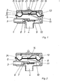
- Fig. 1 das lungengesteuerte Ventil im Schließzustand,
- Fig. 2 den Durchflußzustand,
- Fig. 3 den Sperrzustand.
- 1 shows the lung-controlled valve in the closed state,
- 2 shows the flow state,
- Fig. 3 shows the locked state.
Es sind die in den Figuren 1 bis 3 dargestellten Betriebszustände zu unterscheiden:A distinction must be made between the operating states shown in FIGS. 1 to 3:
Das lungengesteuerte Ventil besitzt ein Ventilgehäuse 1 mit einem Atemgasstutzen 3 für die Zufuhr so-The lung-controlled valve has a
wie einem Abgangsstutzen 4 zur Atemschutzmaske und ist mit einem Deckel 2 abgeschlossen. Das Ventilge- häuse 1 ist zum Deckel 2 hin durch eine Steuermembran 5 getrennt, dabei oberhalb dieser zum Deckel 2 hin eine Außenkammer 24 und unterhalb eine Atmungskammer 6 bildend, deren Druck dem Innendruck der Atemschutzmaske entspricht. Der Atemgasstutzen 3 ist von der Atmungskammer 6 durch ein lungengesteuertes Einlaßventil 7,8 für das Atemgas, aus Ventilsitz 7 und Ventilkörper 8 bestehend, abgetrennt. Der Ventilkörper 8 wird durch eine Schließfeder 9 in Schließrichtung vorgespannt und ist über eine Betätigungsvorrichtung mit der Steuermembran 5 in Kontakt. Dabei ist eine Schubstange 10 mit dem kürzeren Hebelarm eines einarmig ausgebildeten Steuerhebels 11 verbunden. Der Steuerhebel 11 ist im Ventilgehäuse 1 gelagert und liegt mit seinem längeren Hebelarm der Steuermembran 5 an.like a
Die Steuermembran 5 trägt außen einen topfförmigen Haltekragen 12. Hier liegt der längere Hebel eines einarmigen Überdruckhebels 13 an. Dieser ist im Deckel 2 gelagert und wird über seinen kürzeren Hebel von einer halbkreisförmigen Feder 14 gegen die Steuermembran 5 vorgespannt. Dem Überdruckhebel 13 gegenüber ist die Feder 14 in einem Lager 15 im Deckel 2 gehalten.The
Der Überdruckhebel 13 besitzt einen Sperrnocken 16. Diesem gegenüber ist im Deckel 2 das Schubende 23 eines längsbeweglichen Sperrschiebers 17, der am anderen Ende in eine Sperrnase 18 ausläuft, vorhanden. Der Sperrschieber 17 kann über einen Griff 19, der durch einen Schlitz 20 nach außen geführt ist, verschoben werden. Eine Hemmfeder 21 sorgt für zügigen Gang. Beiderseits der Sperrnase 18 des Sperrschiebers 17 trägt der Deckel 2 außerhalb des Haltekragens 12 je eine Anlage 22.The
t Bei dem hier dargestellten Schließzustand herrscht in der Atemschutzmaske und damit auch in der Atmungskammer 6 ein Überdruck, der die Steuermembran 5 gegen die vom Überdruckhebel 13 übertragene Kraft der Feder 14 emporgehoben hat. Die Schließfeder 9 hat über die Schubstange 10 den Steuerhebel 11 der Steuermembran 5 nachgeführt und dabei auch das Einlaßventil 7,8 geschlossen. Der Zufluß des Atemgases ist unterbrochen.In the closed state shown here, there is an overpressure in the breathing mask and thus also in the
Mit einem Einatemzug vermindert sich der Druck in der Atemmaske und der Atmungskammer 6. Dadurch verschiebt der Überdruckhebel 13 unter der Kraft der Feder 14 über die Steuermembran 5,den Steuerhebel 11 und die Schubstange 10 den Ventilkörper 8 in eine geöffnete Stellung. Das Atemgas fließt in die Atemschutzmaske. Mit dem Ende des Einatemzuges baut sich in der Atemschutzmaske aus dem zuströmenden Atemgas wieder ein höherer Überdruck auf, der die Steuermembran 5 und die übrigen Teile wieder in die Lage nach Fig. l bringt. Das Einlaßventil 7,8 schließt wieder.With an inhalation, the pressure in the breathing mask and the
Soll die Atemschutzmaske abgesetzt und trotz des dann fehlenden Überdruckes in der Atmungskammer 6 ein unkontrolliertes Abströmen des Atemgases vermieden werden, dann muß das Einlaßventil 7,8 geschlossen bleiben. Dazu ermöglicht das lungengesteuerte Ventil eine Sperrstellung. Für diese wird der Sperrschieber 17 von Hand an seinem Griff 19 nach rechts verschoben. Sein Schubende 23 hebt dabei über den-Sperrnocken 16 den Überdruckhebel 13 gegen die Kraft der Feder 14 empor und entspannt die Steuermembran 5. Sie hebt sich, da vom Überdruckhebel 13 entlastet, unter der Wirkung der Schließfeder 9. Dabei tritt der Haltekragen 12 in den zwischen den Anlagen 22 des Deckels 2 und der Sperrnase 18 des Sperrschiebers 17 gebildeten Spalt. Nach dem Loslassen des Griffes 19 wird der Sperrschieber 17 durch die Feder 14 über den Sperrnocken 16 in Richtung auf seine Ausgangslage zurückgeschoben und klemmt den Haltekragen 12 im Spalt 12 fest. Diese Sperrstellung wird ohne weiteres Zutun aufrechterhalten. Das Einlaßventil 7,8 hatte sich bereits, ausgelöst durch das Heben der Steuermembran 5, geschlossen.If the respiratory mask is to be removed and an uncontrolled outflow of the breathing gas is to be avoided in spite of the lack of excess pressure in the
Zur Inbetriebnahme aus der Sperrstellung genügt nach dem Aufsetzen der Atemschutzmaske ein tiefer Atemzug. Dieser bewegt die Steuermembran 5 in Richtung zur Atmungskammer 6 und zieht damit den Haltekragen 12 aus dem Spalt heraus. Dadurch wird unmittelbar mit dem gleichzeitigen Öffnen des Einlaßventils 7,8 der Durchflußzustand nach Fig. 2 wieder erreicht. Gleichzeitig schiebt der Sperrnocken 16 den Sperrschieber 17 ganz in die Ausgangsstellung zurück, so daß der weitere Betrieb wieder im Wechsel zwischen Durchfluß- und Schließzustand nach Fig. 1 und 2 verläuft.To start up from the locked position, a deep breath is sufficient after putting on the respirator. This moves the
Claims (4)
Applications Claiming Priority (2)
| Application Number | Priority Date | Filing Date | Title |
|---|---|---|---|
| DE3245717 | 1982-12-10 | ||
| DE3245717A DE3245717C1 (en) | 1982-12-10 | 1982-12-10 | Lung-controlled valve for overpressure operation in the mask interior |
Publications (2)
| Publication Number | Publication Date |
|---|---|
| EP0111754A1 true EP0111754A1 (en) | 1984-06-27 |
| EP0111754B1 EP0111754B1 (en) | 1987-05-06 |
Family
ID=6180305
Family Applications (1)
| Application Number | Title | Priority Date | Filing Date |
|---|---|---|---|
| EP83111402A Expired EP0111754B1 (en) | 1982-12-10 | 1983-11-15 | Respiratory apparatus for positive pressure ventilation |
Country Status (4)
| Country | Link |
|---|---|
| US (1) | US4572176A (en) |
| EP (1) | EP0111754B1 (en) |
| JP (1) | JPS59115055A (en) |
| DE (1) | DE3245717C1 (en) |
Cited By (2)
| Publication number | Priority date | Publication date | Assignee | Title |
|---|---|---|---|---|
| EP0371209A2 (en) * | 1988-11-28 | 1990-06-06 | Auergesellschaft Gmbh | Pulmonarily actuated valve |
| EP0442273A2 (en) * | 1990-02-16 | 1991-08-21 | Decisions Investments Corp. | Pressure balancing a closed ecological system |
Families Citing this family (17)
| Publication number | Priority date | Publication date | Assignee | Title |
|---|---|---|---|---|
| DE3401383A1 (en) * | 1984-01-17 | 1985-07-25 | Drägerwerk AG, 2400 Lübeck | RESPIRATORY MASK WITH OVERPRESSURE IN THE MASK INTERIOR |
| US4683881A (en) * | 1985-10-30 | 1987-08-04 | U.S.D. Corp. | Breathing regulator mouthpiece |
| DE3539668A1 (en) * | 1985-11-08 | 1987-05-21 | Draegerwerk Ag | Lung controlled diaphragm valve for respirator masks |
| FR2644750A1 (en) * | 1989-03-21 | 1990-09-28 | Spirotech Ind Commerc | DEVICE FOR SUPPLYING RESPIRATORY GAS FOR A PLUNGER |
| JPH06191481A (en) * | 1992-12-22 | 1994-07-12 | Zexel Corp | Mouth piece for semi-closed type breather |
| GB9301959D0 (en) * | 1993-02-01 | 1993-03-17 | Sabre Safety Ltd | A valve for use in breathing apparatus |
| GB9319580D0 (en) * | 1993-09-22 | 1993-11-10 | Racal Health & Safety Ltd | Valves |
| GB2315116B (en) * | 1993-09-22 | 1998-03-25 | Racal Health & Safety Ltd | Valves |
| US5551474A (en) * | 1995-06-20 | 1996-09-03 | Chuang; Rung-Chao | Gas flow direct pressure regulator |
| GB9619459D0 (en) * | 1996-09-18 | 1996-10-30 | Jackson Peter J | Breathing apparatus |
| FR2781381B1 (en) * | 1998-07-24 | 2000-09-29 | Intertechnique Sa | ON-DEMAND REGULATOR FOR RESPIRATORY SYSTEM |
| ITGE20010028A1 (en) * | 2001-03-23 | 2002-09-23 | Htm Sport Spa | DISPENSER FOR UNDERWATER RESPIRATORY APPLIANCES. |
| DE102004052173B3 (en) * | 2004-10-27 | 2006-01-12 | Dräger Safety AG & Co. KGaA | Respirator for normal pressure and overpressure operation |
| GB0509369D0 (en) * | 2005-05-07 | 2005-06-15 | Foss Nicholas J | A breathing apparatus demand valve |
| JP5528899B2 (en) * | 2010-04-28 | 2014-06-25 | 興研株式会社 | Supply valve |
| US9278235B1 (en) * | 2012-03-12 | 2016-03-08 | Lynn H. Phillips | Adaptive demand oxygen delivery system |
| EP3397353B1 (en) * | 2015-12-30 | 2022-05-04 | Scott Technologies, Inc. | Respirator mask with air-saver switch |
Citations (2)
| Publication number | Priority date | Publication date | Assignee | Title |
|---|---|---|---|---|
| GB1019986A (en) * | 1962-12-21 | 1966-02-09 | Robertshaw Controls Co | Breathing demand regulator |
| EP0021803A1 (en) * | 1979-06-21 | 1981-01-07 | Chubb Panorama Limited | Valves and breathing apparatus incorporating such valves |
Family Cites Families (6)
| Publication number | Priority date | Publication date | Assignee | Title |
|---|---|---|---|---|
| US986344A (en) * | 1910-07-14 | 1911-03-07 | Reliance Engineering & Mfg Company Of Chicago | Automatic gas-regulator. |
| US1824072A (en) * | 1930-09-22 | 1931-09-22 | Chipley D Bullard | Automatic safety valve |
| US2406888A (en) * | 1944-06-06 | 1946-09-03 | Scott Aviation Corp | Breathing apparatus |
| US3180356A (en) * | 1963-01-07 | 1965-04-27 | American Radiator & Standard | Combination pressure regulator and shut-off valve |
| DE2620170A1 (en) * | 1976-05-07 | 1977-11-17 | Draegerwerk Ag | Lung action controlled air supply respirator - has dosing valve assembly controlled by lever attached to diaphragm |
| SE428760B (en) * | 1979-10-09 | 1983-07-25 | Aga Ab | Breathing mask |
-
1982
- 1982-12-10 DE DE3245717A patent/DE3245717C1/en not_active Expired
-
1983
- 1983-10-19 US US06/543,317 patent/US4572176A/en not_active Expired - Fee Related
- 1983-11-15 EP EP83111402A patent/EP0111754B1/en not_active Expired
- 1983-12-09 JP JP58231599A patent/JPS59115055A/en active Granted
Patent Citations (2)
| Publication number | Priority date | Publication date | Assignee | Title |
|---|---|---|---|---|
| GB1019986A (en) * | 1962-12-21 | 1966-02-09 | Robertshaw Controls Co | Breathing demand regulator |
| EP0021803A1 (en) * | 1979-06-21 | 1981-01-07 | Chubb Panorama Limited | Valves and breathing apparatus incorporating such valves |
Cited By (6)
| Publication number | Priority date | Publication date | Assignee | Title |
|---|---|---|---|---|
| EP0371209A2 (en) * | 1988-11-28 | 1990-06-06 | Auergesellschaft Gmbh | Pulmonarily actuated valve |
| EP0371209A3 (en) * | 1988-11-28 | 1991-12-18 | Auergesellschaft Gmbh | Pulmonarily actuated valve |
| EP0442273A2 (en) * | 1990-02-16 | 1991-08-21 | Decisions Investments Corp. | Pressure balancing a closed ecological system |
| EP0442273A3 (en) * | 1990-02-16 | 1992-04-22 | Space Biospheres Venture | Pressure balancing a closed ecological system |
| US5279081A (en) * | 1990-02-16 | 1994-01-18 | Space Biospheres Ventures | Pressure balancing a closed ecological system |
| US5377458A (en) * | 1990-02-16 | 1995-01-03 | Decisions Team, Inc. | Pressure balancing a closed ecological system |
Also Published As
| Publication number | Publication date |
|---|---|
| JPH0150419B2 (en) | 1989-10-30 |
| DE3245717C1 (en) | 1984-06-07 |
| US4572176A (en) | 1986-02-25 |
| EP0111754B1 (en) | 1987-05-06 |
| JPS59115055A (en) | 1984-07-03 |
Similar Documents
| Publication | Publication Date | Title |
|---|---|---|
| EP0111754B1 (en) | Respiratory apparatus for positive pressure ventilation | |
| DE3015760C2 (en) | Lung-controlled compressed gas breathing apparatus with positive pressure in the breathing mask | |
| DE3229240C2 (en) | Breathing apparatus suitable for overpressure operation | |
| DE2541303C3 (en) | Hand-operated lung ventilation device with a self-expanding bladder | |
| DE1910979A1 (en) | Valve device, especially for use in anesthetic gas delivery systems | |
| CH624013A5 (en) | ||
| DE3401383A1 (en) | RESPIRATORY MASK WITH OVERPRESSURE IN THE MASK INTERIOR | |
| DE3004594A1 (en) | WARNING SIGNAL DEVICE FOR RESPIRATORY DEVICES | |
| DE2646338C3 (en) | Lung-controlled diaphragm valve for compressed gas breathing apparatus | |
| DE1286910B (en) | Lung-controlled breathing gas supply device | |
| DE2620170A1 (en) | Lung action controlled air supply respirator - has dosing valve assembly controlled by lever attached to diaphragm | |
| DE102005058401B3 (en) | Automatic lung regulator for compressed air respiration device, has base housing and diaphragm, which is controlled by human breathing, where rocker arm has control mechanics for regulating breathing air supply to respirator mask | |
| DE1931903A1 (en) | Ventilation device | |
| DE102012214860B3 (en) | Breathing apparatus | |
| DE1491698C3 (en) | Ventilator or anesthesia ventilator | |
| DE3137530C2 (en) | Door operator | |
| DE1063904B (en) | Fast acting device for actuating a valve | |
| DE2203453A1 (en) | WARNING DEVICE FOR VENTILATION DEVICES (RESPIRATORS) | |
| DE1491633C (en) | Ventilator | |
| AT234533B (en) | Pressure regulator with tire inflation connection | |
| DE701631C (en) | Lung operated control device for breathing apparatus, especially high altitude breathing apparatus | |
| AT159002B (en) | Oxygen distribution piece for lung-automatic breathing devices. | |
| DE1131998B (en) | Compressed gas breathing apparatus with a breathing gas supply valve that is lung-controlled by a membrane | |
| DE1898765U (en) | CIRCULAR RESPIRATORY DEVICE. | |
| DE1168946B (en) | Control valve for a compressed air brake of rail vehicles |
Legal Events
| Date | Code | Title | Description |
|---|---|---|---|
| PUAI | Public reference made under article 153(3) epc to a published international application that has entered the european phase |
Free format text: ORIGINAL CODE: 0009012 |
|
| 17P | Request for examination filed |
Effective date: 19831128 |
|
| AK | Designated contracting states |
Designated state(s): FR GB NL SE |
|
| GRAA | (expected) grant |
Free format text: ORIGINAL CODE: 0009210 |
|
| AK | Designated contracting states |
Kind code of ref document: B1 Designated state(s): FR GB NL SE |
|
| ET | Fr: translation filed | ||
| PLBE | No opposition filed within time limit |
Free format text: ORIGINAL CODE: 0009261 |
|
| STAA | Information on the status of an ep patent application or granted ep patent |
Free format text: STATUS: NO OPPOSITION FILED WITHIN TIME LIMIT |
|
| 26N | No opposition filed | ||
| PGFP | Annual fee paid to national office [announced via postgrant information from national office to epo] |
Ref country code: FR Payment date: 19891013 Year of fee payment: 7 |
|
| PGFP | Annual fee paid to national office [announced via postgrant information from national office to epo] |
Ref country code: GB Payment date: 19891031 Year of fee payment: 7 |
|
| PG25 | Lapsed in a contracting state [announced via postgrant information from national office to epo] |
Ref country code: SE Effective date: 19891116 |
|
| PGFP | Annual fee paid to national office [announced via postgrant information from national office to epo] |
Ref country code: NL Payment date: 19891130 Year of fee payment: 7 |
|
| PG25 | Lapsed in a contracting state [announced via postgrant information from national office to epo] |
Ref country code: GB Effective date: 19901115 |
|
| PG25 | Lapsed in a contracting state [announced via postgrant information from national office to epo] |
Ref country code: NL Effective date: 19910601 |
|
| GBPC | Gb: european patent ceased through non-payment of renewal fee | ||
| NLV4 | Nl: lapsed or anulled due to non-payment of the annual fee | ||
| PG25 | Lapsed in a contracting state [announced via postgrant information from national office to epo] |
Ref country code: FR Effective date: 19910731 |
|
| REG | Reference to a national code |
Ref country code: FR Ref legal event code: ST |
|
| EUG | Se: european patent has lapsed |
Ref document number: 83111402.0 Effective date: 19900705 |