EP1387527A1 - Identification des routeurs et des chemins du réseau - Google Patents
Identification des routeurs et des chemins du réseau Download PDFInfo
- Publication number
- EP1387527A1 EP1387527A1 EP02255321A EP02255321A EP1387527A1 EP 1387527 A1 EP1387527 A1 EP 1387527A1 EP 02255321 A EP02255321 A EP 02255321A EP 02255321 A EP02255321 A EP 02255321A EP 1387527 A1 EP1387527 A1 EP 1387527A1
- Authority
- EP
- European Patent Office
- Prior art keywords
- network
- paths
- routers
- router
- communications
- Prior art date
- Legal status (The legal status is an assumption and is not a legal conclusion. Google has not performed a legal analysis and makes no representation as to the accuracy of the status listed.)
- Withdrawn
Links
Images


Classifications
-
- H—ELECTRICITY
- H04—ELECTRIC COMMUNICATION TECHNIQUE
- H04L—TRANSMISSION OF DIGITAL INFORMATION, e.g. TELEGRAPHIC COMMUNICATION
- H04L45/00—Routing or path finding of packets in data switching networks
- H04L45/02—Topology update or discovery
- H04L45/04—Interdomain routing, e.g. hierarchical routing
-
- H—ELECTRICITY
- H04—ELECTRIC COMMUNICATION TECHNIQUE
- H04L—TRANSMISSION OF DIGITAL INFORMATION, e.g. TELEGRAPHIC COMMUNICATION
- H04L45/00—Routing or path finding of packets in data switching networks
- H04L45/02—Topology update or discovery
-
- H—ELECTRICITY
- H04—ELECTRIC COMMUNICATION TECHNIQUE
- H04L—TRANSMISSION OF DIGITAL INFORMATION, e.g. TELEGRAPHIC COMMUNICATION
- H04L45/00—Routing or path finding of packets in data switching networks
- H04L45/26—Route discovery packet
-
- H—ELECTRICITY
- H04—ELECTRIC COMMUNICATION TECHNIQUE
- H04L—TRANSMISSION OF DIGITAL INFORMATION, e.g. TELEGRAPHIC COMMUNICATION
- H04L45/00—Routing or path finding of packets in data switching networks
- H04L45/02—Topology update or discovery
- H04L45/03—Topology update or discovery by updating link state protocols
Definitions
- This invention relates to methods and apparatus for identifying routers, the associated interconnecting communications links and the paths taken by packets traversing those links in a communications network, such as a packet network using the Internet Protocol (IP).
- IP Internet Protocol
- the invention is particularly applicable to networks that use link-state routing protocols such as Open Shortest Path First (OSPF) or Intermediate system-Intermediate system (IS-IS), or any equivalent thereof.
- OSPF Open Shortest Path First
- IS-IS Intermediate system-Intermediate system
- ISPs Internet service providers
- QoS quality of service
- SLAs service level agreements
- MPLS Multi-Protocol Label Switching
- RFC Request for Comments
- a common theme among these technologies is their use of packet classification at the ingress point where a data packet first enters a discrete network (generally referred to in Internet terminology as an autonomous system). Conversely, the same packet will often be declassified at the egress point of that network so that the next network/autonomous system to receive the packet can, if it wishes, reclassify the packet in its own way.
- the classification ensures each packet receives the appropriate treatment when routed through a network.
- the treatment that a packet will receive as it passes through the network will differ depending upon the type of classification given to the packet at the ingress router.
- the intermediate routers coerce routing of the packet onto a different logical path through the network away from the predetermined default path that the packet would normally take if it were unclassified.
- At least one default path is defined for each source and destination within the network. This default path is typically the least-cost path as defined by the Interior Gateway Protocol (IGP) cost metric for each interconnection (described hereinafter in the context of OSPF with reference to Figures 4 to 7).
- IGP Interior Gateway Protocol
- a logical path is therefore an alternative non-default path taken by any packet that receives different routing (packet forwarding) treatment.
- a logical path may for example be a separate physical path from the one that would typically be taken by the packet if it were unclassified.
- a logical path may be defined by different queuing treatment at the intermediate routers. In either example, a classified packet will receive a different set of treatments, depending upon the classification received, giving the packet a different set of transmission characteristics as compared to the same packet were it routed on the default path.
- Each logical path has a set of assigned properties that determine the transmission characteristics for the packets that traverse the path, such as how much bandwidth on the physical interconnection is reserved for that logical path, the level of service ("bronze”, “silver” or “gold”), the maximum permissible jitter, or any specific routers through which the logical path must pass.
- a network operator applying traffic engineering may decide to transmit videoconference traffic that is sensitive to jitter via a dedicated logical path through its MPLS-enabled network. That path is different from other default paths which non-videoconference traffic will take. Despite having potentially more router hops the dedicated path (in this case a separate physical path) carries no other traffic and can therefore easily accommodate the combined voice and video load without introducing unwanted jitter. All other traffic takes the default path, e.g. the route with the smallest overall cost metric as defined by the IGP. Whichever route is taken, all traffic eventually arrives at the egress router and the packets are then declassified ready to be passed to the next network. Without this load balancing all network packets would be routed using the default path and at peak times this may cause the network to become overloaded and discard or delay packets, making the videoconference unusable and causing problems for other data traffic users.
- the traffic-engineering process can be applied at many different levels, for example for different customers, for different services or for combinations of both. Equally, other traffic-management tools such as QoS and SLA mechanisms that have different business objectives could be employed. Both QoS and SLAs require packet classification at the ingress and egress points and both result in other routing policies and the use of logical paths that are different from the default (usually the least-cost) path to route traffic concurrently within the network.
- Many traffic-engineering techniques involve monitoring of the network's operation, for example to audit conformance to agreed QoS or SLA criteria and to trigger timely remedial action or (less desirably) compensation if the criteria are not attained.
- a problem for network management systems attempting such monitoring of traffic-managed networks is to discover where packets enter and leave the network and whether the classification and subsequent treatment of the packet is correct. The network management system should detect incorrect packet classification which could cause traffic to be routed incorrectly, or failure of an internal router which could cause all traffic to follow the same path irrespective of classification, in either case resulting in packets being delayed or discarded and perhaps breaching an SLA.
- the overall Internet is divided into many administrative domains.
- an Internet service provider might constitute a single administrative domain.
- Each administrative domain forms part of the Internet by entering into agreements with neighbouring domains (other ISPs etc.) to form peering or transit relationships to carry each other's traffic and enable the connectivity expected by users.
- An administrative domain contains one or more autonomous systems (ASs).
- An AS is a set of routers typically under a single technical administration (e.g. an ISP), which:
- the Internet consists of many ASs in many administrative domains. At each connection between each AS there are “edge” routers and each edge router has the potential to implement some form of traffic management.
- a large ISP may have many ingress and egress routers interacting with many other ISPs and have many different end customers. Each ingress and egress router could be classifying and routing traffic using many different policies. The enormous challenges involved in deploying, monitoring and managing traffic-management technologies is readily apparent.
- the routing table is generated for example by means of the OSPF link-state protocol described in RFC 2328 (and referred to hereinafter as the OSPF protocol).
- the information contained within the router's link-state database describes the topology to an extent sufficient for that router's operational requirements; such data could in principle be extracted from the routers and be exploited to produce a complete topology description.
- Unfortunately, using current technologies the required data it is not accessible in a manner that satisfies the necessary requirements of scale, accuracy and timeliness whilst ensuring that network integrity is maintained.
- SNMP Simple Network Management Protocol
- a network topology description obtained by using the invention can assist network operators to administer networks deploying traffic management techniques such as MPLS and Differentiated Services, or can be used in deploying core MPLS-enabled IP networks (see RFC 2917), Voice over IP services (also known as Internet Telephony), SLAs and QoS mechanisms.
- traffic management techniques such as MPLS and Differentiated Services
- core MPLS-enabled IP networks see RFC 2917
- Voice over IP services also known as Internet Telephony
- SLAs also known as Internet Telephony
- QoS mechanisms QoS mechanisms.
- the invention facilitates monitoring of the different logical paths and any associated transmission characteristics implemented over the various physical interconnections, routers and sub-networks present in the network.
- a method for identifying a network-wide set of paths potentially taken by packets in a communications network comprising the steps of:
- Network-wide in this context means that the network description produced is not focused on any particular router or other node in the network.
- OSPF for example notionally produces in each router a tree description of paths through the network, with that router as the root of the tree, as a transient step towards generating a desired routing table. Paths between routers that are not needed to forward packets from this "root" router are not included in the tree.
- the present invention generates a description of the network topology in which all routers are equally significant, and in a typical implementation provides a comprehensive view of all paths, not just the default path, between all routers.
- apparatus for identifying a network-wide set of paths potentially taken by packets in a communications network comprising:
- FIG. 1 a notional fragment of the Internet is shown comprising an autonomous system AS1 and portions of two other autonomous systems AS2 and AS3 connected to it.
- the system AS1 contains two edge routers 10 and 12 which provide external connections, to the systems AS2 and AS3 respectively, and three internal routers 14, 16 and 18 which are connected solely to other routers within their own AS.
- the systems AS2 and AS3 likewise include edge routers 20 and 30 respectively, providing connection to the system AS1, as well as internal routers 22, 24, 30 and 34.
- Each AS requires forwarding information, both local to the AS and global between ASs, so that data packets can be routed through the nodes or routers to the correct destinations.
- the routers (and routes) are configured either statically or dynamically using a class of protocols called Exterior Gateway Protocols, e.g. the Border Gateway Protocol (BGP) described in RFC 1771.
- Border Gateway Protocol BGP
- the routers (and routes) are configured either statically or dynamically using a class of protocols called Interior Gateway Protocols (IGPs), such as OSPF, IS-IS or Routing Information Protocol (RIP).
- OSPF Interior Gateway Protocol
- IS-IS Routing Information Protocol
- RIP Routing Information Protocol
- each router is responsible for distributing and maintaining a database describing the topology of an area or zone forming the whole or part of the AS containing that router. This database is known as the link-state database.
- the router On start up, the router is only aware of its own local state, its connected interfaces and networks in accordance with information that is pre-configured by the router's administrator. The process of learning and distributing further network state information, such as connectivity, is achieved by exchanging special data packets defined by the OSPF protocol with other routers within the AS.
- adjacent routers Initially “adjacencies" are formed with neighbouring routers using, for example, packet multicast techniques.
- An adjacency is a relationship formed with each of a router's active neighbours for the purpose of exchanging routing information.
- the adjacent routers exchange information about their state using OSPF link-state description packets formatted in accordance with the protocol. This process continues until both routers share a common view of the topology of their zone of the AS, thereby building a link-state database in each router.
- each router in the AS executes the same algorithm in conjunction with its own copy of the link-state database, to construct a unique routing table comprising a tree of least-cost paths, as defined by the IGP metric, from itself as root to each destination.
- the resultant least cost paths become the default routes taken by all unclassified packets traversing the network.
- sets of networks within the AS can be grouped together into routing areas or zones.
- the topology of a zone is not shared with the rest of the AS containing that zone, to provide a significant reduction in routing traffic. Between zones summary packets are exchanged to ensure inter-zone connectivity.
- each router repeats the information exchange and route calculation process if a change in its network zone occurs.
- a change might involve the addition or removal of a link or router, or a change in a link's costs.
- the packets are, in the absence of new updates, re-broadcast periodically, normally every hour.
- the invention implements passive discovery of the network topology within an AS using a link-state IGP such as OSPF or IS-IS, and creation of an annotated representation of that topology to facilitate the subsequent discovery of a network-wide set of paths through that network.
- the annotated representation describes the AS by means of a directed graph, in which vertices represent routers or networks and edges represent links connected to the routers.
- the annotations indicate discovered data about the router or network represented by each vertex. In the case of routers the annotations indicate associated IP address, a set of interfaces denoted by IP address, and type or function (intra-zone, inter-zone or inter-autonomous system).
- IP address For networks the associated network addresses and netmask, denoted by IP address, and network type (stub, transit or external) are shown.
- Transit networks are those capable of carrying data traffic that is neither locally originated nor locally destined.
- Stub networks are analogous to cul-de-sacs and external networks are destinations to other networks outside the AS.
- FIG. 2 A visual representation of an example of a graph produced in accordance with the invention is shown in Figure 2.
- the edges of the graph connect the individual vertices.
- An edge connects two routers when they are attached via a physical point-to-point link whilst an edge connecting a router to a network indicates that the router has an interface on the network.
- Each edge is annotated with the cost of using that interface for packet forwarding, as defined by the IGP. In OSPF this is known as the link metric.
- the topology discovery process is passive in the sense that the required information is obtained without interacting actively with the routers or other network elements and without generating additional network traffic.
- at least one probe or monitor 40 is connected to the AS at a point where the OSPF packets are present.
- the probe could for example be a low-cost computer, such as a "personal computer”, running a dedicated software program and connected to the AS via an Ethernet card.
- the "logical" point of connection to the network is chosen to ensure that OSPF packets broadcast by the routers traverse that point. Physically, this connection point may be, for example, a port on a router, or a tap into a link between two routers or from a sub-network via a hub or switch.
- OSPF OSPF terms a connection is required at any point in the network traversed by OSPF packets.
- the software program opens a connection in "promiscuous mode" onto the network link or segment of the chosen network zone. Promiscuous mode allows the probe to receive the required OSPF packets irrespective of their LAN destination address. The received packets are allowed to continue their journey through the network without interference (rather than being received and removed from the network).
- the probe 40 does not implement a state machine as described in RFC 2328 to establish an adjacency with any router, as that would require the probe to become an active participant in the OSPF routing protocol, thereby creating spurious link-state database entries in that zone's other routers. Instead the probe 40 remains passive and relies on the flooding process of OSPF packets by the routers in the zone or AS. The probe 40 waits for OSPF packets to arrive on the monitored interface, rather than requesting them using the normal OSPF mechanisms.
- a topology derivation procedure (described below and illustrated in Figures 8 to 13) is executed upon the receipt of every OSPF packet, to build up the desired topology description incrementally.
- the start-up procedure requires the default link-state refresh interval, normally one hour, to have elapsed before a complete topology description is determined. Thereafter by continuing to track the OSPF packets the probe can keep the topology description in step with the state of the network.
- the number of probes required for an AS depends upon the size of the AS and how it is organised. A single probe can generate a complete annotated topology for the zone to which it is connected.
- An OSPF network always has at least one zone, which is known as the backbone. Connection to this backbone is preferred. Experience indicates that many networks are hierarchical in design and a single probe connected to the backbone will provide a very useful annotated topology. To discover a complete annotated topology for a multizone AS, a connection to each active zone is required. However, even a single connection will provide, in addition to the complete annotated topology of the chosen zone, summary information for the networks in other zones in the AS, plus any connections to external networks via the AS's edge routers.
- Each probe 40 monitors the packets traversing the link to which it is connected, and makes copies of selected types of packets described below. It then extracts data from these copies and processes the data to yield information for the annotated topology.
- OSPF protocol Five types of packet are defined in the OSPF protocol, as shown in the following table. For the purposes of the present invention two of these OSPF packet types are used, Hello packets and Link State Update packets, types 1 and 4 respectively. Type Description 1 Hello 2 Database Description 3 Link State Request 4 Link State Update 5 Link State Acknowledgement
- Hello packets are present on OSPF networks, for example on broadcast media such as Ethernets, and are transmitted most frequently, appearing at regular intervals on a given network segment.
- Hello packets can therefore be used to supply the probe 40 with an accurate indication of network time.
- An accurate time stamp is applied to Hello packets on their arrival at the probe.
- a probe based upon a personal computer could obtain an accurate indication of time either from its internal clock or from a Global Positioning System (GPS) receiver in conjunction with the Network Time Protocol (NTP).
- GPS Global Positioning System
- NTP Network Time Protocol
- This form of timer mechanism is a convenient way of providing a timebase for ensuring obsolete information is purged from the probe 40.
- any other form of timer mechanism that can provide an accurate indication of passage of time will suffice.
- the Link State Update packets contain one or more Link State Advertisements (LSAs), which describe the state of either a router (including the state of the router's interfaces and adjacencies) or a network.
- LSAs Link State Advertisements
- the collection of LSAs for a zone comprises the link-state database.
- LSAs are broadcast whenever a change in the network configuration occurs, and at regular intervals to ensure that stale information is not present in the network.
- Each LSA has a header portion (shown in Figure 3) that contains both a key (comprising a combination of fields in the header) and age information that give a unique identity to the LSA within the AS.
- the process of determining if an LSA should be accepted into the link-state database is described in RFC 2328, sections 13.1 and 13.2, and is used by the probe 40 to determine if an LSA it receives is newer than an existing LSA that it already has, and whether that LSA should be accepted into its own link-state database.
- the probe's internal clock is updated and the new time value is used to increment the age field of every LSA in the link-state database. If an LSA's age value thus becomes greater than the OSPF standard architectural constant MaxAge, conventionally set to one hour, the LSA is removed from the link state database (as shown in Figure 8). This process provides a safeguard ensuring that stale LSAs are removed from the probe's link-state database, so that if an updated LSA is missed by the probe or lost due to a temporary link failure, the topology description provided by the probe 40 will not be unduly corrupted.
- the probe's annotated description of the current network topology must be created or refreshed.
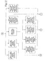
- the procedure for accomplishing this will now be described, with reference to Figures 8 to 13.
- the precise sequence of most of the steps involved is not critical, although step 6 must be performed last.
- the topology could be entirely re-calculated for every link-state database change, or just incrementally in respect of the most recent LSA changes processed. Both approaches are equally valid and the method that proves simpler to implement or more appropriate in a specific implementation can be chosen. In the example described below identifying the vertices of the topology first is convenient and conforms to normal graph construction techniques.
- Step 1 ( Figure 9): Identify the active sub-networks within the zone and the active routers in those sub-networks; this is accomplished using the LSAs that contain information about the network elements within the current zone, specifically Type 2 Network-LSAs and a subset of Type 1 Router-LSAs.
- Network-LSAs specify the routers that are attached to a sub-network that supports more than one router.
- the Network Mask field in a Network-LSA (see Figure 5) describes the size, or range, of the address space of the sub-network, and the IP address in the Link State Identifier field of the LSA's header ( Figure 3) identifies the first IP address in the sub-network. Lists of active routers on that sub-network are also provided, the routers being denoted by IP address in the Attached Router field ( Figure 5).
- Each LSA contains one entry for each and every active router on the sub-network.
- Router-LSAs can be sub-divided depending upon the type of link being described, and each Router-LSA may describe several links of different types.
- the types of connections are identified as follows: Type Description 1 Point-to-point connection to another router 2 Connection to a transit network 3 Connection to a stub network 4 Virtual link Only those Router-LSAs containing information on type 3 links to a stub network are considered in this step.
- each Link Identifier field Figure 4
- Link Data field give the IP address and network mask for a connection to a stub network on the router identified by the Advertising Router field of the LSA's header.
- the penultimate router on a sub-network fails so that the sub-network no longer has two or more routers the corresponding Network-LSA may not be actively withdrawn from the link-state database.
- the Network-LSA is still present, it is superseded by a new type 3 Router-LSA containing an entry describing a connection to a stub network. Therefore, in order to ensure only active routers on active sub-networks are considered in this step, the information contained in these two types of LSAs are combined so that a router defined by an entry in a type 3 Router-LSA takes precedence over information about the same router defined in a Network LSA.
- Step 2 ( Figure 9): Specify the topology's internal network vertices.
- a vertex is created for each active network in the list of active sub-networks derived in step 1.
- the vertex is annotated with the IP address and the network mask thus specifying the identity and address range of the sub-network represented by the vertex.
- These vertices are also annotated with the type 'internal network'.
- Step 3 ( Figure 9): Specify the topology's router vertices and their associated interfaces:
- Step 3.2 The type 1 Router-LSAs containing entries describing links that are point-to-point connections are analysed. As before the router IP address is added to the list of vertices and the IP addresses of the router's interfaces identified by the Link Data field are also added.
- Step 3.3 A similar process is employed for the type 4 Router-LSAs containing entries describing virtual links (virtual links are described in RFC 2328, sections 3.1 and 15).
- Step 3.4 Next the type 3 Router-LSAs, containing information about connections to stub networks, are analysed. The process is the same as that for type 2 Router-LSAs containing entries describing the connections to transit networks. However, in this case the router address itself is added as the associated router interface.
- the Link Data field for this type of Router-LSA entry does not describe the router's interface, but describes the network mask of the connected stub network. The IP address interface for the router's interface cannot therefore be determined. For the purposes of specifying the connections, as described later, the start point for this type of link is considered to be the router itself.
- Step 3.5 ( Figure 10): The specified router vertices are annotated with their associated types.
- the router types are marked according to the E and B flags in the VEB field of the Router-LSA ( Figure 4). If the B flag is set then the router is marked as inter-area; if the E flag is set the router is marked as inter-AS or inter-network; otherwise the vertex is marked as intra-area.
- Step 3.6 (Figure 11): For each ASExternal-LSA a router vertex is added, if it does not already exist, as identified by the Advertising Router field of the LSA header, with an associated interface as identified by the IP address in the 'Forwarding Address' field ( Figure 7). The vertex is annotated as an 'inter-AS router'. Similarly, for each Summary-LSA a check is made that a vertex exists for the router identified by the IP address in the Advertising Router field, and that it is annotated as being an 'intra-area router'. This step has two purposes: to check the integrity of the data and to speed the discovery process on probe start-up, during the period where a complete topology has not yet been obtained.
- Step 4.1 ( Figure 12): Specify the topology's inter-area network vertices.
- the type 3 and type 4 Summary-LSAs are considered. These LSAs describe connections to inter-area destinations comprising either networks (for type 3 Summary-LSAs) or inter-area routers (for type 4 Summary-LSAs).
- a network vertex identified by the IP address Advertising Router field and the Network Mask field ( Figure 6) is added to the list of vertices. These vertices are annotated with the type 'summary network'.
- Step 4.2 Specify the topology's inter-AS network vertices.
- the type 5 ASExternal-LSAs are used to specify a set of external vertices that represent routes to networks external to the network containing the probe 40. These are routes whose existence has been made known via either pre-configured static route descriptions or via an Exterior Gateway Protocol such as BGP-4. For each of these external routes the OSPF routers will issue an ASExternal-LSA.
- For each LSA a vertex is added to the vertex list for the network identified by the IP address in the Link State Identifier field of the LSA's header and the Network Mask ( Figure 7). The vertex is annotated with the type 'external network'.
- Step 5 ( Figures 12 and 13): Specify the edges in the network:
- Step 5.2 Specify the stub edges.
- Router-LSAs containing entries that describe connections to stub networks are used to specify edges between the relevant router vertices and network vertices with only one entry and exit point.
- an edge is added starting at the router's interface; in this instance the interface has the same address as the router itself (in effect addressing the router directly) and ending at a sub-network.
- the edge start is denoted by the Adverting Router field and the destination is the sub-network as defined by the Link Identifier and Link Data fields.
- the sub-network address is denoted by the IP address in the Link Identifier field and the network mask by the Link Data.
- the edge is annotated with the cost of traversing the link defined in the Metric/Cost field.
- Step 5.3 Specify the point-to-point edges.
- Router-LSAs describing point-to-point and virtual links are used to specify edges that directly interconnect router vertices. Virtual links are described in RFC 2328 sections 3.1 and 15 and for the purposes of generating a topology they can be handled in the same way as point-to-point links.
- Step 5.4 Specify the inter-area edges.
- Summary-LSAs are used to specify edges connecting router vertices to vertices describing any inter-area destinations. There are two types, type 3 which describe destinations that are IP networks and type 4 which describe destinations that are other inter-area routers.
- For each type 3 Summary-LSA an edge is added from the router's interface (in this instance having the same address as the router itself, in effect addressing the router directly) to the inter-area sub-network as defined by the Link State Identifier field and the Network Mask field.
- the Network Mask field is not meaningful and must be zero, and the Link State Identifier is the IP address of the inter-AS router.
- the edge is annotated with the cost of traversing the link as defined in the Metric/Cost field ( Figure 6).
- Step 5.5 Specify the inter-AS edges.
- ASExternal-LSAs are used to specify edges connecting router vertices to vertices describing any external destinations outside the AS.
- an edge is added from the router interface denoted by the Forwarding Address field ( Figure 7) to the external network defined by the Link State Identifier field in the LSA's header and the Network Mask field ( Figure 7).
- the edge is annotated with the cost of traversing the link defined by the E bit field and the Metric/Cost field. If the E-bit is unset then the metric, or cost, is defined in the same units as the other internal link metrics of the other edges. If the E-bit is set then the cost of the link is considered larger than any other internal link state path.
- Step 6 Maintain a graph of viable paths.
- the probe 40 must eliminate any out-of-date information, thus ensuring that only viable network paths are reported to a traffic-management or other application using the topology information.
- the probe's link state database may contain LSAs that arrived prior to a network outage or failure that caused a partition in the network. Fresh LSA updates from any router that resides on the network on the far side of the partition failure point will not have been able to reach the probe 40 where they would be used to remove the stale information.
- the probe 40 must eliminate the vertices and edges representing affected routers, networks and links.
- FIG 14 shows the resultant network configuration.
- the probe 40 will continue to receive updates from the routers 10 and 14 on its side of the failure or 'network partition'. However the router 12 lying beyond the partition cannot communicate the change to either of the routers 10 and 14. Consequently the link-state databases in the routers 10 and 14 and the probe 40 will continue to contain LSAs sent from router 12. However the information in these LSAs can no longer be considered reliable as it is from outside the probe's current known routing zone.
- the purpose of the probe 40 is to create a description of all possible and viable network paths, so this description should not include portions of the network beyond the point where the failed routers 16 and 18 are situated.
- each vertex in the graph is assessed by systematically inspecting all the vertices using a recursive procedure starting at the vertex representing the point where the probe 40 is connected to the network.
- the start vertex for the recursive algorithm could either be a router or a network depending upon which element is logically closest to the probe 40. For example, if the probe is connected directly via a tap on a point-to-point connection then the start point is the logically nearest router. Or, if the probe is connected on a transit sub-network then the sub-network should be used. A transit sub-network provides multiple reachable connections to the overall network via each of its connected routers, and these multiple connections must be considered during any reach-ability calculations.
- the resultant graph can be exported to an external application (e.g. for traffic management) and includes only the active interconnected vertices currently known to the probe 40.
- the graph can be exported by the probe 40 to one or more external applications via an appropriate form of inter-process communication.
- RPC Remote Procedure Call mechanism
- CORBA Common Object Request Broker Architecture
- RMI Java Remote Method Invocations
- the software for the probe 40 could also be embedded directly into application software to create a simple, small, lightweight, portable system that could be transported around the network by the operator as required.
- the annotated graph data could be made available so that an application is made aware of each change as it occurs. This is sometimes referred to as a 'publish and subscribe' mechanism whereby the application subscribes to the changes as they are published. Alternatively, and more simply, a new topology could be delivered to an application on demand.
- the exported topology information could take several forms but will include some type of listing of the active vertices and active edges.
- the listing of active vertices typically includes: the vertex identity denoted by the IP address and network mask or prefix length; the type of network element represented by the vertex, for example, network, inter-AS, inter-zone and intra-zone, and the intra-zone and the zone to which they belong. Also included could be the list of interfaces, denoted by IP address.
- the list of edges typically includes the vertices to which they are connected, denoted by IP address and network prefix and the cost or metric of using the link represented by the edge. Also included in the list of edges could be the interface used on the router, also denoted by IP address.
- edges and vertices that become inactive or a network change can be removed from the topology description by specifying the vertices in terms of IP address and network prefix. Similarly edges to be removed can be identified in terms of the two connecting vertices.
- annotation information such as edge metric or vertex type, can also be supplied but is not strictly necessary.
- An application makes use of the annotated graph data to determine the set of current active logical paths by, for example, extracting a list of those vertices providing any inter-AS connectivity. Vertices of this type comprise the ingress and egress points of the network and are the most likely places where traffic classification would be applied as described above.
- the application can directly query the routers represented by those vertices to determine if in fact traffic classification is present; one common mechanism that could be used for such a query is SNMP (RFC 1157).
- SNMP and the associated Management Information Bases (MIBs) for the chosen traffic management systems are available on the majority of routers and provide a widely accepted mechanism for access to this type of network management data.
- the internal router vertices could also be searched if there is a likelihood of any internal traffic classification being present on the network. This is less likely but in some situations may occur.
- LSP MPLS Label Switched Path
- the discovered topology data can be used to determine the network-wide set of paths, including the set of default paths for the topology. It is important to note that multiple logical paths from different source routers may potentially traverse a single interconnection. As a consequence the network-wide set of paths must be considered when determining alternative logical paths. Failure to consider the network-wide set of paths may lead to over-specification and congestion on a router, sub-network or interconnection that services multiple logical paths from different source/ingress routers. The network-wide set of paths is required to ensure the validity of these calculations.
- the network operator can, for example, use the combined information, including the set of network-wide paths and their associated costs/metrics through the AS, in conjunction with the overlaid requested traffic management information (about the LSP) to monitor the logical non-default path deployment.
- This combined information provides a valuable aid to the network operator, for example in designing new paths, LSP provisioning, and ensuring that the network is performing to design specification.
- the application will calculate that the default path from the router 10 to the router 12 is via the router 18.
- An active MPLS LSP is discovered between the routers 10 and 18 that requires a reserved bandwidth equating to 75% utilisation of the link maximum capacity. This LSP has been installed at the request of the manager of AS3 who requires a guaranteed level of bandwidth for connection to AS2.
- a second path is also discovered between the routers 10 and 12 via the routers 14 and 16, that is being used for another purpose; this path requires 20% of the bandwidth on those links.
- the application determines that the first LSP is on the default path, and that the combined load of the first and second LSPs does not equate to more than the available maximum capacity. The application can therefore recommend that an alternative path for the first LSP would be via the router 14 and the router 16, rather than via the default path through the router 18.
- a mechanism to inform the external application of any change to the LSP may help the operator to mitigate the impacts of such a failure by providing an immediate warning of the LSP change.
- One such mechanism that allows routers to provide feedback is the SNMP trap mechanism.
- An SNMP trap once set, will inform an external application of a change in the target MIB data.
- the new LSP, or any changes to the characteristics of the LSP can then be overlaid over the changed topology once again providing near-real time feedback of LSP behaviour.
- the annotated topology provided by the probe 40 is therefore able to assist operators in various network management tasks including those described above.
- the described process could also be applied, but is not limited to, other forms of traffic management and other technologies that employ routing over separate logical paths via packet classification at ingress and egress routers, as alternatives to typical least-cost path routing, such as Differentiated Services, Virtual Private Networks (VPNs), Voice over IP, SLAs and QoS mechanisms.
- VPNs Virtual Private Networks
- SLAs Voice over IP
Priority Applications (6)
| Application Number | Priority Date | Filing Date | Title |
|---|---|---|---|
| EP02255321A EP1387527A1 (fr) | 2002-07-30 | 2002-07-30 | Identification des routeurs et des chemins du réseau |
| EP03771204A EP1527556A2 (fr) | 2002-07-30 | 2003-07-25 | Identification de routeurs et de chemins de reseau |
| US10/521,777 US20060056328A1 (en) | 2002-07-30 | 2003-07-25 | Identifying network rotuters and paths |
| JP2004523982A JP2005535174A (ja) | 2002-07-30 | 2003-07-25 | パスの集合の識別装置及び識別方法 |
| CN038143798A CN1663176A (zh) | 2002-07-30 | 2003-07-25 | 标识网络路由器和路径 |
| PCT/GB2003/003308 WO2004012393A2 (fr) | 2002-07-30 | 2003-07-25 | Identification de routeurs et de chemins de reseau |
Applications Claiming Priority (1)
| Application Number | Priority Date | Filing Date | Title |
|---|---|---|---|
| EP02255321A EP1387527A1 (fr) | 2002-07-30 | 2002-07-30 | Identification des routeurs et des chemins du réseau |
Publications (1)
| Publication Number | Publication Date |
|---|---|
| EP1387527A1 true EP1387527A1 (fr) | 2004-02-04 |
Family
ID=30011248
Family Applications (2)
| Application Number | Title | Priority Date | Filing Date |
|---|---|---|---|
| EP02255321A Withdrawn EP1387527A1 (fr) | 2002-07-30 | 2002-07-30 | Identification des routeurs et des chemins du réseau |
| EP03771204A Withdrawn EP1527556A2 (fr) | 2002-07-30 | 2003-07-25 | Identification de routeurs et de chemins de reseau |
Family Applications After (1)
| Application Number | Title | Priority Date | Filing Date |
|---|---|---|---|
| EP03771204A Withdrawn EP1527556A2 (fr) | 2002-07-30 | 2003-07-25 | Identification de routeurs et de chemins de reseau |
Country Status (5)
| Country | Link |
|---|---|
| US (1) | US20060056328A1 (fr) |
| EP (2) | EP1387527A1 (fr) |
| JP (1) | JP2005535174A (fr) |
| CN (1) | CN1663176A (fr) |
| WO (1) | WO2004012393A2 (fr) |
Cited By (13)
| Publication number | Priority date | Publication date | Assignee | Title |
|---|---|---|---|---|
| EP1705850A1 (fr) * | 2005-03-21 | 2006-09-27 | Rf Monolithics, Inc. | Appareil et procédé pour collecter d'information de routage dans un réseau basé sur une topologie maillée |
| EP1727322A1 (fr) * | 2005-05-24 | 2006-11-29 | Agilent Technologies, Inc. | Poursuite de la topologie de gestion de trafic dans un système autonome |
| WO2007069960A1 (fr) * | 2005-12-16 | 2007-06-21 | Telefonaktiebolaget Lm Ericsson (Publ) | Cartographie inter-domaine |
| WO2007093742A2 (fr) * | 2006-02-16 | 2007-08-23 | France Telecom | Procede d'estimation d'une distance entre deux terminaux appartenant a un reseau de recouvrement superpose a au moins un reseau sous-jacent |
| EP1864449A2 (fr) * | 2005-03-28 | 2007-12-12 | Cisco Technology, Inc. | Procede et appareil permettant de creer et d'actualiser un organe d'archivage de points de test pour le diagnostic du niveau de service de reseaux prives virtuels en reseau |
| US7684347B2 (en) | 2004-12-23 | 2010-03-23 | Solera Networks | Method and apparatus for network packet capture distributed storage system |
| CN101247267B (zh) * | 2008-03-19 | 2010-09-29 | 中兴通讯股份有限公司 | 网管系统中三层虚拟专用网络拓扑自动发现的方法及装置 |
| CN102811144A (zh) * | 2012-08-16 | 2012-12-05 | 北京傲天动联技术有限公司 | Nms拓扑发现性能测试系统及其方法 |
| US8521732B2 (en) | 2008-05-23 | 2013-08-27 | Solera Networks, Inc. | Presentation of an extracted artifact based on an indexing technique |
| US8625642B2 (en) | 2008-05-23 | 2014-01-07 | Solera Networks, Inc. | Method and apparatus of network artifact indentification and extraction |
| US8666985B2 (en) | 2011-03-16 | 2014-03-04 | Solera Networks, Inc. | Hardware accelerated application-based pattern matching for real time classification and recording of network traffic |
| EP2924930A2 (fr) | 2014-03-25 | 2015-09-30 | Telefonaktiebolaget L M Ericsson (PUBL) | Découverte de chemin dans des réseaux de transport de données basée sur l'inférence statistique |
| EP2988451A1 (fr) * | 2014-08-22 | 2016-02-24 | Vodafone IP Licensing limited | Procédé et système de mise en correspondance de configurations différentes |
Families Citing this family (53)
| Publication number | Priority date | Publication date | Assignee | Title |
|---|---|---|---|---|
| JP2003099341A (ja) * | 2001-09-20 | 2003-04-04 | Canon Inc | ネットワークデバイス管理装置、管理システム及び管理方法、並びにネットワークデバイス |
| US7698366B2 (en) * | 2004-02-12 | 2010-04-13 | Avaya, Inc. | Method and apparatus for facilitating the transportation of medical images on a communication network |
| US20050198269A1 (en) * | 2004-02-13 | 2005-09-08 | Champagne Andrew F. | Method and system for monitoring border gateway protocol (BGP) data in a distributed computer network |
| US20060029035A1 (en) * | 2004-03-25 | 2006-02-09 | Chase Christopher J | Method and apparatus for selecting routes for distribution within IP networks |
| US7620033B2 (en) * | 2004-05-21 | 2009-11-17 | Alcatel-Lucent Usa Inc. | Method for optimal path selection in traversal of packets through network address translators |
| US7965620B2 (en) * | 2004-05-25 | 2011-06-21 | Telcordia Licensing Company, Llc | Method, computer product and system for correlating events in a network |
| US20060039288A1 (en) * | 2004-08-17 | 2006-02-23 | National Applied Research Laboratories National Center For High-Performance Computing | Network status monitoring and warning method |
| JP4634456B2 (ja) | 2004-09-09 | 2011-02-16 | アバイア インコーポレーテッド | ネットワーク・トラフィックのセキュリティのための方法およびシステム |
| US8572234B2 (en) * | 2004-11-30 | 2013-10-29 | Hewlett-Packard Development, L.P. | MPLS VPN fault management using IGP monitoring system |
| US8549176B2 (en) | 2004-12-01 | 2013-10-01 | Cisco Technology, Inc. | Propagation of routing information in RSVP-TE for inter-domain TE-LSPs |
| US20060182129A1 (en) * | 2005-02-16 | 2006-08-17 | Mutch Karl N | Distributed markup and processing apparatus and method |
| KR100714690B1 (ko) * | 2005-04-07 | 2007-05-04 | 삼성전자주식회사 | 네트워크를 구성하는 노드들과 브리지의 위상을 검출하는방법 및 장치 |
| US8228818B2 (en) | 2005-06-24 | 2012-07-24 | At&T Intellectual Property Ii, Lp | Systems, methods, and devices for monitoring networks |
| US7467154B2 (en) * | 2005-06-29 | 2008-12-16 | Microsoft Corporation | Producing a locally optimal path through a lattice by overlapping search |
| US20070110034A1 (en) * | 2005-11-14 | 2007-05-17 | Broadcom Corporation, A California Corporation | Pathways analysis and control in packet and circuit switched communication networks |
| US7668173B2 (en) * | 2005-12-01 | 2010-02-23 | Azalea Networks | Method and system for an adaptive wireless routing protocol in a mesh network |
| JP4681472B2 (ja) * | 2006-02-24 | 2011-05-11 | 富士通株式会社 | トポロジ情報収集プログラム、トポロジ情報収集装置およびトポロジ情報収集方法 |
| US9043487B2 (en) * | 2006-04-18 | 2015-05-26 | Cisco Technology, Inc. | Dynamically configuring and verifying routing information of broadcast networks using link state protocols in a computer network |
| US8161185B2 (en) * | 2006-04-24 | 2012-04-17 | Cisco Technology, Inc. | Method and apparatus for assigning IPv6 link state identifiers |
| US7929524B2 (en) * | 2006-09-29 | 2011-04-19 | Cisco Technology, Inc. | Apparatus and method to hide transit only multi-access networks in OSPF |
| CN101192951B (zh) * | 2006-11-29 | 2011-04-20 | 华为技术有限公司 | IPv6网络链路利用率测量方法、测量装置及IPv6网络路由器 |
| US8391354B2 (en) * | 2007-05-14 | 2013-03-05 | Broadcom Corporation | Method and system for transforming uncompressed video traffic to network-aware ethernet traffic with A/V bridging capabilities and A/V bridging extensions |
| US8238338B2 (en) * | 2007-09-14 | 2012-08-07 | Cisco Technology, Inc. | Interior gateway protocol summarization preserving internet protocol reachability information |
| US20090097418A1 (en) * | 2007-10-11 | 2009-04-16 | Alterpoint, Inc. | System and method for network service path analysis |
| US20090161658A1 (en) * | 2007-12-19 | 2009-06-25 | Solar Winds.Net | Method for selecting VOIP call path to monitor |
| US8400452B2 (en) * | 2008-05-08 | 2013-03-19 | Motorola Solutions, Inc. | Method and system for segmented propagation visualization |
| US9264341B2 (en) * | 2009-07-24 | 2016-02-16 | Broadcom Corporation | Method and system for dynamic routing and/or switching in a network |
| US8289961B2 (en) * | 2009-08-20 | 2012-10-16 | Telefonaktiebolaget L M Ericsson (Publ) | Link state identifier collision handling |
| WO2011077609A1 (fr) * | 2009-12-25 | 2011-06-30 | パナソニック株式会社 | Système de reconnaissance de position de réseau et dispositif de reconnaissance de position de terminal |
| JP2010124512A (ja) * | 2010-03-11 | 2010-06-03 | Cloud Scope Technologies Inc | ネットワーク情報提示装置及び方法 |
| JP5604928B2 (ja) * | 2010-03-26 | 2014-10-15 | 富士通株式会社 | 監視装置および監視プログラム |
| US9210046B2 (en) * | 2011-03-14 | 2015-12-08 | Hewlett Packard Enterprise Development Lp | Zone-based network traffic analysis |
| US8976711B2 (en) * | 2011-10-07 | 2015-03-10 | Futurewei Technologies, Inc. | Simple topology transparent zoning in network communications |
| JP5771832B2 (ja) * | 2012-02-14 | 2015-09-02 | 株式会社日立製作所 | 伝送システム、管理計算機、及び論理パス構築方法 |
| US11159804B1 (en) * | 2012-09-13 | 2021-10-26 | Arris Enterprises Llc | QoE feedback based intelligent video transport stream tuning |
| US9350640B2 (en) * | 2013-02-25 | 2016-05-24 | Futurewei Technologies, Inc. | Constructing a topology-transparent zone |
| US9379964B2 (en) * | 2013-03-11 | 2016-06-28 | Futurewei Technologies, Inc. | Discovering a topology—transparent zone |
| CN104168197A (zh) * | 2013-05-16 | 2014-11-26 | 宇宙互联有限公司 | 传输管理装置、系统及方法 |
| US20150074260A1 (en) * | 2013-09-11 | 2015-03-12 | Cisco Technology, Inc. | Auto discovery and topology rendering in substation networks |
| US9660897B1 (en) * | 2013-12-04 | 2017-05-23 | Juniper Networks, Inc. | BGP link-state extensions for segment routing |
| CN104125154B (zh) * | 2014-08-12 | 2017-09-26 | 华为技术有限公司 | 网络拓扑发现方法和设备 |
| US9838246B1 (en) | 2014-09-30 | 2017-12-05 | Juniper Networks, Inc. | Micro-loop prevention using source packet routing |
| US9929949B2 (en) * | 2015-06-29 | 2018-03-27 | Google Llc | Systems and methods for inferring network topology and path metrics in wide area networks |
| CN105100713B (zh) * | 2015-07-10 | 2018-04-06 | 华洋通信科技股份有限公司 | 基于ospf协议虚拟化的煤矿应用业务流分离方法 |
| US10701152B2 (en) * | 2015-09-24 | 2020-06-30 | Hewlett Packard Enterprise Development Lp | Memory system management |
| CN105577426B (zh) * | 2015-12-10 | 2018-03-20 | 北京匡恩网络科技有限责任公司 | 不完全信息下基于网络探针的网络拓扑图自动发现方法 |
| CN107301504B (zh) * | 2017-06-12 | 2018-06-15 | 合肥工业大学 | 基于混合蛙跳—路径重连的生产运输协同调度方法和系统 |
| CN109274605B (zh) * | 2017-07-18 | 2021-06-08 | 中国科学院声学研究所 | 一种适用于分组交换网络的同步传输方法 |
| CN109309616B (zh) * | 2017-07-27 | 2022-03-01 | 中兴通讯股份有限公司 | 基于isis协议的通告方法及装置 |
| CN113596059B (zh) * | 2021-08-19 | 2023-06-20 | 中国电子科技集团公司电子科学研究院 | 一种在标识网络中实现实时三层网络隔离的方法及系统 |
| CN114244761B (zh) * | 2021-12-08 | 2023-10-31 | 中盈优创资讯科技有限公司 | 一种基于is-is的设备自动发现方法及装置 |
| US11792301B1 (en) * | 2022-09-22 | 2023-10-17 | Amazon Technologies, Inc. | Parallelized automated creation of proxy manifests |
| US20240106695A1 (en) * | 2022-09-28 | 2024-03-28 | Level 3 Communications, Llc | Name-Based Routing Through Networks |
Citations (5)
| Publication number | Priority date | Publication date | Assignee | Title |
|---|---|---|---|---|
| US5917808A (en) * | 1997-01-17 | 1999-06-29 | Fluke Corporation | Method of identifying device types on a local area network using passive monitoring |
| EP1098491A2 (fr) * | 1999-11-08 | 2001-05-09 | Agilent Technologies Inc. | Systéme et méthode pour identifier les unités reliées de données de protocole |
| US6252856B1 (en) * | 1996-12-03 | 2001-06-26 | Nortel Networks Limited | Method and apparatus for minimizing calculations required to construct multicast trees |
| WO2002039673A1 (fr) * | 2000-11-07 | 2002-05-16 | Telefonaktiebolaget Lm Ericsson (Publ) | Surveillance scalaire en temps reel de la qualite de service et analyse de satisfaction abonne en fonction du service dans des reseaux ip |
| GB2371442A (en) * | 2000-11-01 | 2002-07-24 | Agilent Technologies Inc | Monitoring communication network configuration by probing and characterising network data streams |
Family Cites Families (15)
| Publication number | Priority date | Publication date | Assignee | Title |
|---|---|---|---|---|
| US5398012A (en) * | 1992-11-24 | 1995-03-14 | International Business Machines Corporation | Distributed processing of route selection across networks and subnetworks |
| US5682479A (en) * | 1995-05-05 | 1997-10-28 | Silicon Graphics, Inc. | System and method for network exploration and access |
| US5987521A (en) * | 1995-07-10 | 1999-11-16 | International Business Machines Corporation | Management of path routing in packet communications networks |
| US5699347A (en) * | 1995-11-17 | 1997-12-16 | Bay Networks, Inc. | Method and apparatus for routing packets in networks having connection-oriented subnetworks |
| US5854899A (en) * | 1996-05-09 | 1998-12-29 | Bay Networks, Inc. | Method and apparatus for managing virtual circuits and routing packets in a network/subnetwork environment |
| US5996021A (en) * | 1997-05-20 | 1999-11-30 | At&T Corp | Internet protocol relay network for directly routing datagram from ingress router to egress router |
| US6275470B1 (en) * | 1999-06-18 | 2001-08-14 | Digital Island, Inc. | On-demand overlay routing for computer-based communication networks |
| US7035934B1 (en) * | 2000-03-23 | 2006-04-25 | Verizon Corporate Services Group Inc. | System and method for improving traffic analysis and network modeling |
| US6836465B2 (en) * | 2001-11-29 | 2004-12-28 | Ipsum Networks, Inc. | Method and system for path identification in packet networks |
| US7042834B1 (en) * | 2000-07-28 | 2006-05-09 | Cisco Technology, Inc. | Method and system for routing communications among computer networks |
| US6744739B2 (en) * | 2001-05-18 | 2004-06-01 | Micromuse Inc. | Method and system for determining network characteristics using routing protocols |
| US6990111B2 (en) * | 2001-05-31 | 2006-01-24 | Agilent Technologies, Inc. | Adaptive path discovery process for routing data packets in a multinode network |
| US7277383B2 (en) * | 2001-10-05 | 2007-10-02 | Samsung Electronics Co., Ltd. | Redundancy mechanization protocol for a massively parallel router |
| US7120118B2 (en) * | 2001-10-18 | 2006-10-10 | Intel Corporation | Multi-path analysis for managing machine communications in a network |
| US7239613B1 (en) * | 2002-07-30 | 2007-07-03 | Nortel Networks Limited | Selective purging of routing data packets in a network |
-
2002
- 2002-07-30 EP EP02255321A patent/EP1387527A1/fr not_active Withdrawn
-
2003
- 2003-07-25 US US10/521,777 patent/US20060056328A1/en not_active Abandoned
- 2003-07-25 EP EP03771204A patent/EP1527556A2/fr not_active Withdrawn
- 2003-07-25 CN CN038143798A patent/CN1663176A/zh active Pending
- 2003-07-25 WO PCT/GB2003/003308 patent/WO2004012393A2/fr not_active Application Discontinuation
- 2003-07-25 JP JP2004523982A patent/JP2005535174A/ja active Pending
Patent Citations (5)
| Publication number | Priority date | Publication date | Assignee | Title |
|---|---|---|---|---|
| US6252856B1 (en) * | 1996-12-03 | 2001-06-26 | Nortel Networks Limited | Method and apparatus for minimizing calculations required to construct multicast trees |
| US5917808A (en) * | 1997-01-17 | 1999-06-29 | Fluke Corporation | Method of identifying device types on a local area network using passive monitoring |
| EP1098491A2 (fr) * | 1999-11-08 | 2001-05-09 | Agilent Technologies Inc. | Systéme et méthode pour identifier les unités reliées de données de protocole |
| GB2371442A (en) * | 2000-11-01 | 2002-07-24 | Agilent Technologies Inc | Monitoring communication network configuration by probing and characterising network data streams |
| WO2002039673A1 (fr) * | 2000-11-07 | 2002-05-16 | Telefonaktiebolaget Lm Ericsson (Publ) | Surveillance scalaire en temps reel de la qualite de service et analyse de satisfaction abonne en fonction du service dans des reseaux ip |
Cited By (19)
| Publication number | Priority date | Publication date | Assignee | Title |
|---|---|---|---|---|
| US7684347B2 (en) | 2004-12-23 | 2010-03-23 | Solera Networks | Method and apparatus for network packet capture distributed storage system |
| US7855974B2 (en) | 2004-12-23 | 2010-12-21 | Solera Networks, Inc. | Method and apparatus for network packet capture distributed storage system |
| US7606169B2 (en) | 2005-03-21 | 2009-10-20 | Rf Monolithics, Inc. | System and method for collecting routing information in a mesh network |
| EP1705850A1 (fr) * | 2005-03-21 | 2006-09-27 | Rf Monolithics, Inc. | Appareil et procédé pour collecter d'information de routage dans un réseau basé sur une topologie maillée |
| EP1864449A4 (fr) * | 2005-03-28 | 2011-09-28 | Cisco Tech Inc | Procede et appareil permettant de creer et d'actualiser un organe d'archivage de points de test pour le diagnostic du niveau de service de reseaux prives virtuels en reseau |
| EP1864449A2 (fr) * | 2005-03-28 | 2007-12-12 | Cisco Technology, Inc. | Procede et appareil permettant de creer et d'actualiser un organe d'archivage de points de test pour le diagnostic du niveau de service de reseaux prives virtuels en reseau |
| EP1727322A1 (fr) * | 2005-05-24 | 2006-11-29 | Agilent Technologies, Inc. | Poursuite de la topologie de gestion de trafic dans un système autonome |
| WO2007069960A1 (fr) * | 2005-12-16 | 2007-06-21 | Telefonaktiebolaget Lm Ericsson (Publ) | Cartographie inter-domaine |
| WO2007093742A2 (fr) * | 2006-02-16 | 2007-08-23 | France Telecom | Procede d'estimation d'une distance entre deux terminaux appartenant a un reseau de recouvrement superpose a au moins un reseau sous-jacent |
| WO2007093742A3 (fr) * | 2006-02-16 | 2007-12-27 | France Telecom | Procede d'estimation d'une distance entre deux terminaux appartenant a un reseau de recouvrement superpose a au moins un reseau sous-jacent |
| CN101247267B (zh) * | 2008-03-19 | 2010-09-29 | 中兴通讯股份有限公司 | 网管系统中三层虚拟专用网络拓扑自动发现的方法及装置 |
| US8521732B2 (en) | 2008-05-23 | 2013-08-27 | Solera Networks, Inc. | Presentation of an extracted artifact based on an indexing technique |
| US8625642B2 (en) | 2008-05-23 | 2014-01-07 | Solera Networks, Inc. | Method and apparatus of network artifact indentification and extraction |
| US8666985B2 (en) | 2011-03-16 | 2014-03-04 | Solera Networks, Inc. | Hardware accelerated application-based pattern matching for real time classification and recording of network traffic |
| CN102811144A (zh) * | 2012-08-16 | 2012-12-05 | 北京傲天动联技术有限公司 | Nms拓扑发现性能测试系统及其方法 |
| CN102811144B (zh) * | 2012-08-16 | 2015-02-04 | 北京傲天动联技术股份有限公司 | Nms拓扑发现性能测试系统及其方法 |
| EP2924930A2 (fr) | 2014-03-25 | 2015-09-30 | Telefonaktiebolaget L M Ericsson (PUBL) | Découverte de chemin dans des réseaux de transport de données basée sur l'inférence statistique |
| US9331951B2 (en) | 2014-03-25 | 2016-05-03 | Telefonaktiebolaget L M Ericsson (Publ) | Path discovery in data transport networks based on statistical inference |
| EP2988451A1 (fr) * | 2014-08-22 | 2016-02-24 | Vodafone IP Licensing limited | Procédé et système de mise en correspondance de configurations différentes |
Also Published As
| Publication number | Publication date |
|---|---|
| EP1527556A2 (fr) | 2005-05-04 |
| WO2004012393A2 (fr) | 2004-02-05 |
| CN1663176A (zh) | 2005-08-31 |
| WO2004012393A3 (fr) | 2004-03-18 |
| US20060056328A1 (en) | 2006-03-16 |
| JP2005535174A (ja) | 2005-11-17 |
Similar Documents
| Publication | Publication Date | Title |
|---|---|---|
| EP1387527A1 (fr) | Identification des routeurs et des chemins du réseau | |
| Filsfils et al. | Segment routing architecture | |
| EP1727322A1 (fr) | Poursuite de la topologie de gestion de trafic dans un système autonome | |
| US7436838B2 (en) | Automatic prioritization of BGP next-hop in IGP | |
| US7978708B2 (en) | Automatic route tagging of BGP next-hop routes in IGP | |
| US8625420B2 (en) | System and method for increasing granularity of prefix control in a computer network | |
| King et al. | The Application of the Path Computation Element Architecture to the Determination of a Sequence of Domains in MPLS and GMPLS | |
| US7522603B2 (en) | Technique for efficiently routing IP traffic on CE-CE paths across a provider network | |
| US7814227B2 (en) | Computation of a shortest inter-domain TE-LSP across a set of autonomous systems | |
| EP1859561B1 (fr) | Algorithme pour selection de peripheriques de secours de fournisseur | |
| US7619982B2 (en) | Active probe path management | |
| JP4109692B2 (ja) | ラベルスイッチネットワークにおけるセッション確立方法及びラベルスイッチノード | |
| JP2007129702A (ja) | Vpnトポロジの準リアルタイム更新を発見及び提供する方法及びシステム | |
| CN101288266A (zh) | 自治系统间流量工程标签交换路径路由信息的动态检索 | |
| JP6193473B2 (ja) | コンピュータ実施方法、コンピュータプログラム製品及びコンピュータ | |
| US7702765B1 (en) | Techniques for automatically creating an iBGP mesh | |
| US7779123B2 (en) | System and method for building network model in network management application | |
| JP2000278264A (ja) | データネットワーク監視方法 | |
| Talaulikar | RFC 9552: Distribution of Link-State and Traffic Engineering Information Using BGP | |
| Romeral et al. | Multi-domain G/MPLS recovery paths using PCE | |
| Htira et al. | STAMP: Towards A Scalable Topology Announcement and Management Protocol |
Legal Events
| Date | Code | Title | Description |
|---|---|---|---|
| PUAI | Public reference made under article 153(3) epc to a published international application that has entered the european phase |
Free format text: ORIGINAL CODE: 0009012 |
|
| AK | Designated contracting states |
Kind code of ref document: A1 Designated state(s): AT BE BG CH CY CZ DE DK EE ES FI FR GB GR IE IT LI LU MC NL PT SE SK TR |
|
| AX | Request for extension of the european patent |
Extension state: AL LT LV MK RO SI |
|
| AKX | Designation fees paid | ||
| REG | Reference to a national code |
Ref country code: DE Ref legal event code: 8566 |
|
| STAA | Information on the status of an ep patent application or granted ep patent |
Free format text: STATUS: THE APPLICATION IS DEEMED TO BE WITHDRAWN |
|
| 18D | Application deemed to be withdrawn |
Effective date: 20040805 |