EP1387462A2 - Co-generated power supply system - Google Patents
Co-generated power supply system Download PDFInfo
- Publication number
- EP1387462A2 EP1387462A2 EP03254832A EP03254832A EP1387462A2 EP 1387462 A2 EP1387462 A2 EP 1387462A2 EP 03254832 A EP03254832 A EP 03254832A EP 03254832 A EP03254832 A EP 03254832A EP 1387462 A2 EP1387462 A2 EP 1387462A2
- Authority
- EP
- European Patent Office
- Prior art keywords
- power
- storage battery
- load
- commercial
- power source
- Prior art date
- Legal status (The legal status is an assumption and is not a legal conclusion. Google has not performed a legal analysis and makes no representation as to the accuracy of the status listed.)
- Granted
Links
Images


Classifications
-
- H—ELECTRICITY
- H02—GENERATION; CONVERSION OR DISTRIBUTION OF ELECTRIC POWER
- H02M—APPARATUS FOR CONVERSION BETWEEN AC AND AC, BETWEEN AC AND DC, OR BETWEEN DC AND DC, AND FOR USE WITH MAINS OR SIMILAR POWER SUPPLY SYSTEMS; CONVERSION OF DC OR AC INPUT POWER INTO SURGE OUTPUT POWER; CONTROL OR REGULATION THEREOF
- H02M3/00—Conversion of DC power input into DC power output
- H02M3/22—Conversion of DC power input into DC power output with intermediate conversion into AC
- H02M3/24—Conversion of DC power input into DC power output with intermediate conversion into AC by static converters
- H02M3/28—Conversion of DC power input into DC power output with intermediate conversion into AC by static converters using discharge tubes with control electrode or semiconductor devices with control electrode to produce the intermediate AC
- H02M3/325—Conversion of DC power input into DC power output with intermediate conversion into AC by static converters using discharge tubes with control electrode or semiconductor devices with control electrode to produce the intermediate AC using devices of a triode or a transistor type requiring continuous application of a control signal
- H02M3/335—Conversion of DC power input into DC power output with intermediate conversion into AC by static converters using discharge tubes with control electrode or semiconductor devices with control electrode to produce the intermediate AC using devices of a triode or a transistor type requiring continuous application of a control signal using semiconductor devices only
- H02M3/33569—Conversion of DC power input into DC power output with intermediate conversion into AC by static converters using discharge tubes with control electrode or semiconductor devices with control electrode to produce the intermediate AC using devices of a triode or a transistor type requiring continuous application of a control signal using semiconductor devices only having several active switching elements
- H02M3/33576—Conversion of DC power input into DC power output with intermediate conversion into AC by static converters using discharge tubes with control electrode or semiconductor devices with control electrode to produce the intermediate AC using devices of a triode or a transistor type requiring continuous application of a control signal using semiconductor devices only having several active switching elements having at least one active switching element at the secondary side of an isolation transformer
- H02M3/33584—Bidirectional converters
-
- H—ELECTRICITY
- H02—GENERATION; CONVERSION OR DISTRIBUTION OF ELECTRIC POWER
- H02J—ELECTRIC POWER NETWORKS; CIRCUIT ARRANGEMENTS OR SYSTEMS FOR SUPPLYING OR DISTRIBUTING ELECTRIC POWER; SYSTEMS FOR STORING ELECTRIC ENERGY
- H02J3/00—Circuit arrangements for AC mains or AC distribution networks
- H02J3/38—Arrangements for feeding a single network from two or more generators or sources in parallel; Arrangements for feeding already energised networks from additional generators or sources in parallel
-
- H—ELECTRICITY
- H02—GENERATION; CONVERSION OR DISTRIBUTION OF ELECTRIC POWER
- H02J—ELECTRIC POWER NETWORKS; CIRCUIT ARRANGEMENTS OR SYSTEMS FOR SUPPLYING OR DISTRIBUTING ELECTRIC POWER; SYSTEMS FOR STORING ELECTRIC ENERGY
- H02J7/00—Circuit arrangements for charging or discharging batteries or for supplying loads from batteries
- H02J7/34—Parallel operation in networks using both storage and other DC sources, e.g. providing buffering
-
- H—ELECTRICITY
- H02—GENERATION; CONVERSION OR DISTRIBUTION OF ELECTRIC POWER
- H02J—ELECTRIC POWER NETWORKS; CIRCUIT ARRANGEMENTS OR SYSTEMS FOR SUPPLYING OR DISTRIBUTING ELECTRIC POWER; SYSTEMS FOR STORING ELECTRIC ENERGY
- H02J2101/00—Supply or distribution of decentralised, dispersed or local electric power generation
- H02J2101/40—Hybrid power plants, i.e. a plurality of different generation technologies being operated at one power plant
-
- H—ELECTRICITY
- H02—GENERATION; CONVERSION OR DISTRIBUTION OF ELECTRIC POWER
- H02J—ELECTRIC POWER NETWORKS; CIRCUIT ARRANGEMENTS OR SYSTEMS FOR SUPPLYING OR DISTRIBUTING ELECTRIC POWER; SYSTEMS FOR STORING ELECTRIC ENERGY
- H02J2207/00—Details of circuit arrangements for charging or discharging batteries or supplying loads from batteries
- H02J2207/20—Charging or discharging characterised by the power electronics converter
-
- H—ELECTRICITY
- H02—GENERATION; CONVERSION OR DISTRIBUTION OF ELECTRIC POWER
- H02J—ELECTRIC POWER NETWORKS; CIRCUIT ARRANGEMENTS OR SYSTEMS FOR SUPPLYING OR DISTRIBUTING ELECTRIC POWER; SYSTEMS FOR STORING ELECTRIC ENERGY
- H02J2207/00—Details of circuit arrangements for charging or discharging batteries or supplying loads from batteries
- H02J2207/40—Details of circuit arrangements for charging or discharging batteries or supplying loads from batteries adapted for charging from various sources, e.g. AC, DC or multivoltage
-
- H—ELECTRICITY
- H02—GENERATION; CONVERSION OR DISTRIBUTION OF ELECTRIC POWER
- H02J—ELECTRIC POWER NETWORKS; CIRCUIT ARRANGEMENTS OR SYSTEMS FOR SUPPLYING OR DISTRIBUTING ELECTRIC POWER; SYSTEMS FOR STORING ELECTRIC ENERGY
- H02J9/00—Circuit arrangements for emergency or stand-by power supply, e.g. for emergency lighting
- H02J9/04—Circuit arrangements for emergency or stand-by power supply, e.g. for emergency lighting in which the distribution system is disconnected from the normal source and connected to a standby source
- H02J9/06—Circuit arrangements for emergency or stand-by power supply, e.g. for emergency lighting in which the distribution system is disconnected from the normal source and connected to a standby source with automatic change-over, e.g. UPS systems
- H02J9/067—Circuit arrangements for emergency or stand-by power supply, e.g. for emergency lighting in which the distribution system is disconnected from the normal source and connected to a standby source with automatic change-over, e.g. UPS systems using multi-primary transformers, e.g. transformer having one primary for each AC energy source and a secondary for the loads
-
- Y—GENERAL TAGGING OF NEW TECHNOLOGICAL DEVELOPMENTS; GENERAL TAGGING OF CROSS-SECTIONAL TECHNOLOGIES SPANNING OVER SEVERAL SECTIONS OF THE IPC; TECHNICAL SUBJECTS COVERED BY FORMER USPC CROSS-REFERENCE ART COLLECTIONS [XRACs] AND DIGESTS
- Y02—TECHNOLOGIES OR APPLICATIONS FOR MITIGATION OR ADAPTATION AGAINST CLIMATE CHANGE
- Y02E—REDUCTION OF GREENHOUSE GAS [GHG] EMISSIONS, RELATED TO ENERGY GENERATION, TRANSMISSION OR DISTRIBUTION
- Y02E10/00—Energy generation through renewable energy sources
- Y02E10/50—Photovoltaic [PV] energy
- Y02E10/56—Power conversion systems, e.g. maximum power point trackers
-
- Y—GENERAL TAGGING OF NEW TECHNOLOGICAL DEVELOPMENTS; GENERAL TAGGING OF CROSS-SECTIONAL TECHNOLOGIES SPANNING OVER SEVERAL SECTIONS OF THE IPC; TECHNICAL SUBJECTS COVERED BY FORMER USPC CROSS-REFERENCE ART COLLECTIONS [XRACs] AND DIGESTS
- Y02—TECHNOLOGIES OR APPLICATIONS FOR MITIGATION OR ADAPTATION AGAINST CLIMATE CHANGE
- Y02E—REDUCTION OF GREENHOUSE GAS [GHG] EMISSIONS, RELATED TO ENERGY GENERATION, TRANSMISSION OR DISTRIBUTION
- Y02E10/00—Energy generation through renewable energy sources
- Y02E10/70—Wind energy
- Y02E10/76—Power conversion electric or electronic aspects
-
- Y—GENERAL TAGGING OF NEW TECHNOLOGICAL DEVELOPMENTS; GENERAL TAGGING OF CROSS-SECTIONAL TECHNOLOGIES SPANNING OVER SEVERAL SECTIONS OF THE IPC; TECHNICAL SUBJECTS COVERED BY FORMER USPC CROSS-REFERENCE ART COLLECTIONS [XRACs] AND DIGESTS
- Y02—TECHNOLOGIES OR APPLICATIONS FOR MITIGATION OR ADAPTATION AGAINST CLIMATE CHANGE
- Y02P—CLIMATE CHANGE MITIGATION TECHNOLOGIES IN THE PRODUCTION OR PROCESSING OF GOODS
- Y02P80/00—Climate change mitigation technologies for sector-wide applications
- Y02P80/20—Climate change mitigation technologies for sector-wide applications using renewable energy
-
- Y—GENERAL TAGGING OF NEW TECHNOLOGICAL DEVELOPMENTS; GENERAL TAGGING OF CROSS-SECTIONAL TECHNOLOGIES SPANNING OVER SEVERAL SECTIONS OF THE IPC; TECHNICAL SUBJECTS COVERED BY FORMER USPC CROSS-REFERENCE ART COLLECTIONS [XRACs] AND DIGESTS
- Y02—TECHNOLOGIES OR APPLICATIONS FOR MITIGATION OR ADAPTATION AGAINST CLIMATE CHANGE
- Y02P—CLIMATE CHANGE MITIGATION TECHNOLOGIES IN THE PRODUCTION OR PROCESSING OF GOODS
- Y02P90/00—Enabling technologies with a potential contribution to greenhouse gas [GHG] emissions mitigation
- Y02P90/40—Fuel cell technologies in production processes
Definitions
- the present invention relates to a novel co-generated power supply system, which is useful for co-generated power supply in combination of natural energy and stable energy such as a fuel cell and power storage energy during off-peak periods such as nighttime, and especially, which can efficiently supply electric power to a load by connecting a plurality of alternating current (AC) and direct current (DC) energy sources to each other via an electronic transformer, a diode and an OR circuit.
- AC alternating current
- DC direct current
- Examples of household electric appliances which currently prevail in Japan and can be safely used with both AC and DC supplies include a light bulb, an inverter type fluorescent lamp and an electric tool, and further, there can be used, in principle, inverter types of an air-conditioner, a refrigerator, a microwave oven, a vacuum cleaner, a personal computer and a facsimile except for some types in which a voltage doubler rectifying circuit or an AC protective circuit is incorporated.
- a dimmer, a space heating appliance and an automatic rice cooker of a thyristor phase control system cannot be used with the DC under current circumstances.
- the appliance only for the AC and the household electric appliance for both of the AC and the DC must be used by separating indoor wiring systems (i.e., sockets) independently of each other.
- the DC power generation energy always is reversely converted into the commercial AC through an inverter in the conventional system, and then, is converted into the DC again within an actual load, and further, is converted into a high frequency inverter or a variable frequency AC power, so as to drive an electric motor or a compressor, thereby increasing a conversion loss.
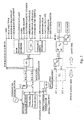
- Fig. 1 is a diagram illustrating the classification of suitability of AC and DC power supply of conventional household electric appliances in a low-tension power distribution system in the case where AC and DC energy sources are used in a co-generated power supply system, and the relationship between the suitability and conversion efficiency.
- ⁇ 1 , ⁇ 2 and ⁇ 3 represent the efficiency in the case where a fluorescent lamp is lighted by the solar cell; and
- ⁇ 1 , ⁇ 2 , ⁇ 3 and ⁇ 4 represent the efficiency in the case where a personal computer or a facsimile is operated.
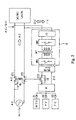
- Fig. 2 is a diagram illustrating a conventional example of a solar cell and a wind turbine generator in a low-tension power distribution system in the case where electric power is supplied directly to a load from AC and DC energy sources.
- electric power is supplied directly to both of a commercial AC power source and a load via a system linking inverter (popularly called a power conditioner) in the solar cell; in contrast, in the wind turbine generator, since the time fluctuations in generated electric power are sharp, the generated electric power is stored in a storage battery, and then, Systems are linked via a bidirectional converter having both of electric charging and discharging functions. In this manner, the solar cell and the wind turbine generator have been configured in systems independent of each other.
- a system linking inverter popularly called a power conditioner
- an effective power generation time during the daytime ranges from 6 hours to 8 hours even on a bright day.
- a weekly or monthly rate of a power generation time in the wind turbine generator greatly depends on seasons or regions, the average rate of the power generation time in Japan is assumed to be smaller than the rate of the power generation time in the solar cell. This is a factor that the solar cell and the wind turbine generator have not prevailed in comparison with in Europe or the U.S.
- control equipment such as an inverter is provided for each electric power of the energy generating source of a low operating rate in the above-described manner, the cost of the entire system is increased, thereby leading to one factor of inhibition of a popular use.
- the efficiency can be enhanced by the amount of removed efficiency ⁇ 1 of the inverter in comparison with the prior art illustrated in Fig. 1.
- the efficiency ⁇ 1 of the DC-AC inverter of several kilowatt or less including an insulating function is about 90% and the efficiency ⁇ 1 ' of the electronic transformer of the same capacity is about 94% to 95%, resulting in ⁇ 1 ⁇ ⁇ 1 '.
- the system of the present invention can still achieve better efficiency.
- Fig. 4 is a diagram illustrating a co-generated power supply system in an embodiment according to the present invention.
- DC power sources include a wind turbine generator WTG (Wind Turbine Generator), a solar cell PV (Photo Voltaic) and a fuel cell FC (Fuel Cell) whose rated voltages are made equal to a rated voltage of a storage battery B (Battery).
- WTG Wind Turbine Generator
- PV Photo Voltaic
- FC Fuel Cell
- the co-generated power supply system is configured such that AC power from a commercial AC power source Utility is supplied to a load Lac/dc operable with both AC and DC supplies until the storage battery B is fully charged by the DC power sources WTG, PV and FC; DC power from the storage battery B is supplied to the load Lac/dc for both of the AC and the DC when the storage battery B has been fully charged; and AC power from the commercial AC power source Utility is supplied to the load Lac/dc as the storage battery B proceeds to be discharged and approaches the terminal period of discharging.
- the DC power supply and the AC power supply are designed to be switched by a control circuit, not illustrated.
- the storage battery B is electrically charged normally by the wind turbine generator WTG and the solar cell PV. In the case of insufficient generated electric power, the storage battery B is electrically charged by the fuel cell FC during the daytime; in contrast, the storage battery B is electrically charged via a charger CHG1 during off-peak periods, e.g. the nighttime, that is, in a time period in which an electric charge (tariff) is lower than that during peak periods, e.g. the daytime.
- a charger CHG1 during off-peak periods, e.g. the nighttime, that is, in a time period in which an electric charge (tariff) is lower than that during peak periods, e.g. the daytime.
- a switch SW is opened in response to a command from a control circuit, and an AC relay RL is restored to switch the AC power source to the DC power source, thereby sequentially supplying the DC power to the load Lac/dc.
- the switch SW is closed in response to a command from the control circuit, the AC power is supplied again by the commercial AC power source Utility.
- Fig. 5 is a diagram illustrating a co-generated power supply system in another embodiment according to the present invention.
- the co-generated power supply system in the embodiment illustrated in Fig. 5 comprises a bidirectional DC-DC converter Conv and a two-winding electronic transformer 2.
- the two-winding electronic transformer 2 includes a high frequency transformer HFT having the function of matching and insulating a voltage on a side of a storage battery and a voltage on a side of a load; modulation/demodulation semiconductor switches SW3 and SW2 which are connected to a coil on the side of the storage battery and a coil on the side of the load and are operated at 10 kHz to 50 kHz; and a filter F2 connected onto the side of the load.
- the two-winding electronic transformer 2 is used for both AC and DC and has two bidirectional input/output terminals 2a and 2b.
- One bidirectional input/output terminal 2a is connected to an output side of a DC power source; in contrast, the other bidirectional input/output terminal 2b is connected in a T-shaped manner between a commercial AC power source Utility and a load Lac/dc operable with both AC and DC supplies.
- AC power from the commercial AC power source Utility is supplied to the load Lac/dc not via the two-winding electronic transformer 2 until a storage battery B is fully charged by DC power sources WTG, PV and FC; DC power from the DC power sources WTG, PV and FC and the storage battery B is supplied to the load Lac/dc via the two-winding electronic transformer 2 when the storage battery B has been fully charged or the commercial AC power source Utility fails; the electric power is replenished from the fuel cell FC when the storage battery B is being discharged; the AC power is supplied to the load Lac/dc from the commercial AC power source Utility in an off-peak period for the electric power supply, and further, the storage battery B is electrically charged by the bidirectional function of the two-winding electronic transformer 2 and the AC/DC converting function.
- the fluctuations in voltage of the storage battery B are adjusted by the voltage adjusting function of the bidirectional DC-DC converter Conv irrespective of the electric charging or discharging time, such that the voltage can be stably supplied to the load Lac/dc.
- the two-winding electronic transformer 2 can transmit bidirectional energy forward and backward by the bidirectional function and the AC/DC converting function, so that it can function as a charger (i.e., corresponding to the charger CHG illustrated in Fig. 1) for the off-peak electric power in association with the bidirectional DC-DC converter Conv.
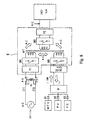
- Fig. 6 is a diagram illustrating a co-generated power supply system in a further embodiment according to the present invention.
- the co-generated power supply system in the embodiment illustrated in Fig. 6 comprises a three-winding electronic transformer 3 having three bidirectional input/output terminals 3a, 3b and 3c for both of an AC and a DC in order to insulate between a commercial AC power source Utility and a load Lac/dc operable with both AC and DC supplies and adjust fluctuations in power source voltage, wherein DC power sources WTG, PV and FC and a storage battery B, the commercial AC power source Utility and the load Lac/dc are connected In a mutually insulating manner.
- the three-winding electronic transformer 3 includes a high frequency transformer HFT having the function of matching and insulating a voltage on the side of the storage battery and a voltage on the side of the load; modulation/demodulation semiconductor switches SW1, SW3 and SW2 which are operated at 10 kHz to 50 kHz and are connected to a coil on the side of the commercial AC power source, a coil on the side of the storage battery and a coil on the side of the load and; and filters F1 and F2 connected onto the side of the commercial AC power source and the side of the load.
- HFT high frequency transformer
- SW1, SW3 and SW2 which are operated at 10 kHz to 50 kHz and are connected to a coil on the side of the commercial AC power source, a coil on the side of the storage battery and a coil on the side of the load and
- filters F1 and F2 connected onto the side of the commercial AC power source and the side of the load.
- AC power from the commercial AC power source Utility is supplied to the load Lac/dc via the three-winding electronic transformer 3 until the storage battery B is fully charged by the DC power sources WTG, PV and FC; DC power from the DC power sources WTG, PV and FC and the storage battery B is supplied to the load Lac/dc for both of the AC and the DC via the three-winding electronic transformer 3 when the storage battery B has been fully charged or the commercial AC power source Utility fails; the electric power is replenished from the fuel cell FC when the storage battery B is being discharged; the AC power from the commercial AC power source Utility is supplied to the load Lac/dc in an off-peak period for the electric power supply, and further, the storage battery B is charged by the bidirectional function of the three-winding electronic transformer 3 and the AC/DC converting function.
- the voltage can be adjusted by a pulse width modulation (PWM) control or a pulse phase modulation (PPM) control of the modulation/demodulation semiconductor switches SW1 and SW2, thereby stably supplying a load voltage with respect to the fluctuations in the commercial AC power source Utility and the DC power sources WTG, PV and FC, and simultaneously, charging can be achieved by the off-peak electric power via the modulation/demodulation semiconductor switches SW1 and SW3.
- PWM pulse width modulation
- PPM pulse phase modulation
- the circuit is configured such that the AC power and the DC power are switched over via contacts CT1, CT2 and CT3 of an AC relay RL, so that the electric power is supplied to the load Lac/dc for both of the AC and the DC, and further, energy of each of the wind turbine generator WTG, the solar cell PV and the fuel cell FC is consumed on the side of the load without any reverse flow of the AC current (i.e., system linkage) on the side of the commercial AC power source via the storage battery B.
- the AC current i.e., system linkage
- Figs. 7 and 8 are diagrams illustrating co-generated power supply systems in still further embodiments according to the present invention.
- a storage battery B and a bidirectional DC-DC converter Conv are connected directly to each other, thereby achieving a reverse flow of the AC current.
- the reverse flow of off-peak electric power is not allowed in accordance with an electric charging contract in Japan.
- the reverse flow of the AC current is allowed.
- the reverse flow of the AC current is allowed in any case from the viewpoint of pure technique.
- AC power from a commercial AC power source Utility is supplied to an AC only load Lac via neither the bidirectional DC-DC converter Conv nor a two-winding electronic transformer 4 in Fig. 7 while via a three-winding electronic transformer 5 in Fig. 8 until a storage battery B is fully charged by DC power sources WTG, PV and FC.
- DC power from the DC power sources WTG, PV and FC and the storage battery B is supplied to the load Lac by converting the DC power into a single-phase full-wave rectification waveform by half cycle sinusoidal wave modulation in the bidirectional DC-DC converter Conv, alternately reversing a high frequency modulation phase of two or two pairs of, i.e., four unidirectional semiconductor switches, not illustrated, which constitute a modulation/demodulation semiconductor switch SW3 connected onto the side of the storage battery in a high frequency transformer HFT in a two-winding electronic transformer 4 illustrated in Fig. 7 or a three-winding electronic transformer 5 illustrated in Fig.
- the DC power is converted into the AC power by the energy bidirectional transmitting characteristics of the two-winding electronic transformer 4 illustrated in Fig. 7 or the three-winding electronic transformer 5 illustrated in Fig. 8 when the storage battery B has been almost fully charged at a light load and the commercial AC power source does not fail, for automatic phase synchronization on the side of the commercial AC power source so as to achieve a reverse flow of the AC current.
- Fig. 9 illustrates an example of operation of an inverter at the time of charging of off-peak electric power
- Fig. 10 illustrates an example of operation of an inverter in the case of a reverse flow of the DC current from the storage battery B to the load Lac/dc operable with both AC and DC supplies or the commercial AC power source Utility.
- switches S7 and S8 and diodes D7 and D8 constituting the bidirectional DC-DC converter Conv are designated by the same reference characters in a circuit device in Figs. 11 to 14, described later. Other reference characters are the same as those in Figs. 4 to 8.
- the modulation/demodulation semiconductor switch SW3 (see Fig. 7) on the side of the storage battery inside of the two-winding electronic transformer 4 can be actually constituted of two unidirectional semiconductor switches S5 and S6, as illustrated later in Fig. 13, or two pairs of (i.e., four) unidirectional semiconductor switches, not illustrated, in the case of a bridge.
- the modulation/demodulation semiconductor switch SW2 (see Fig. 7) on the side of the load can be constituted of two switches S3 and S4, as illustrated in Fig. 13.
- the modulation/demodulation semiconductor switch SW3 on the side of the storage battery is constituted of the two unidirectional semiconductor switches S5 and S6, a DC output voltage 6 of a two-phase half-wave is generated (see Figs. 9 and 13) at both ends of a capacitor C6 of the bidirectional DC-DC converter Conv in the case of the sinusoidal wave AC in the switches S3 and S4 on the side of the load and the side of the commercial AC power source (see Fig. 13) by switching the drive phase of a modulation wave of the unidirectional semiconductor switches SS and S6 (see Fig. 13) per half cycle of a commercial frequency.
- a boost type power factor correction i.e., a PFC -IC
- the other switch S7 is stopped, so that the storage battery B is electrically charged by the energy accumulated in a choke coil CH via the diode D7.
- the electric charging voltage of the storage battery B becomes higher than an output maximum amplitude of the two-winding electronic transformer 4 because of a boost operation, thereby achieving sufficient charging.
- the switch S7 is driven in response to a PWM signal whose sinusoidal wave is modulated, thereby generating a two-phase half-wave or single-phase full-wave rectification output 6 on the output side of the filter consisting of the choke coil CH and the capacitor C6.
- the resultant output is modulated at a high frequency (10 kHz to 50kHz) by the unidirectional semiconductor switches S5 and S6 (see Figs. 7 and 13) of the modulation/demodulation semiconductor switch SW3.
- the drive phase of the modulation pulse is reversed per half cycle of the commercial frequency on the side of the unidirectional semiconductor switches S5 and S6 (see Figs. 7 and 13) such that the sinusoidal wave is achieved on the side of the switches S3 and S4 (see Figs. 7 and 13) of the modulation/demodulation semiconductor switch SW2.
- the sinusoidal wave AC output can be taken out on the output side of the two-winding electronic transformer 4, that is, the side of the load and the side of the commercial AC power source.
- the system consisting of the commercial AC power source Utility, the AC only load Lac and the storage battery B is completely insulated by the use of the three-winding electronic transformer 5 illustrated in Fig. 8, the high frequency transformer HFT can achieve an envelope modulated operation at every sinusoidal wave commercial AC frequency in a winding turn ratio which can match with each voltage value, whereby the AC only load in the prior art can be used.
- Fig. 11 is a specific example of the embodiment illustrated in Fig. 5. Reference characters used here are the same as those used in Fig. 5, and therefore, a description will be given of only additional reference characters.
- reference character TM designates a timer for AC/DC power supply and off-peak electric power charging, and it is controlled by a control circuit CONT-2.
- Reference character CONT-1 denotes a control circuit for a wind turbine generator WTG.
- the control circuit CONT-1 is a generally known control circuit for performing rectification in the case where the wind turbine generator WTG is operated by an AC, like in a generator for an automobile while for performing voltage adjustment as it is in the case where the wind turbine generator WTG is operated by a DC.
- Reference characters S3 and S4 designate bidirectional semiconductor switches, in which two unidirectional semiconductor switches are connected back to back (ie., Back to Back Connection) for switching the AC and the DC, as enlarged in Fig. 11.
- Reference characters S5 to S8 denote unidirectional semiconductor switches; D5 to D8, internal or external diodes; C1 to C6, capacitors; CH, a choke coil; and N2 to N4, coils for a high frequency transformer HFT.
- the unidirectional semiconductor switches S5 to S7 are stopped, and a DC voltage is generated across the capacitor C6 via the bidirectional semiconductor switches S3 and S4, the high frequency transformer HFT and the diodes D5 and D6.
- a storage battery B can be charged by adjusting the DC voltage via the unidirectional semiconductor switch S8 and the diode D7.
- AC power is supplied to a load Lac/dc operable with both AC and DC supplies.
- a solar cell during the daytime or wind turbine generator irrespective of a time zone may be mainly used while the charging by the use of the commercial AC power source Utility may be auxiliary or may not be performed.
- the AC power supply is immediately switched to DC power supply from DC power sources WTG, PV and FC and the storage battery B owing to restoration of an AC relay RL, and then, the DC power is supplied onto the side of the load through a two -winding electronic transformer 2, so that the load Lac/dc can be continued to be operated.
- the unidirectional semiconductor switch S8 is stopped, and therefore, the DC voltage is controlled, that is, is adjusted to be decreased by the unidirectional semiconductor switch S7 and the diode D8.
- the fuel cell FC is operated according to the discharging of the storage battery B, thereby continuing the discharging.
- a switch SW is turned off by the timer TM in response to a command from the control circuit CONT-2 in the case where the storage battery B has been fully charged even without any failure, so that the AC power supply is switched to the DC power supply, thus achieving a co-generated power supply by the natural energy and the fuel cell.
- Fig. 12 is a specific example of the embodiment illustrated in Fig. 6.
- an electronic transformer is a type of three-windings, for insulating each of power sources from a load and stabilizing fluctuations of a commercial AC power source Utility by a PWM or PPM control, as described above. Explanation will be made below on schematic operation of a three-winding electronic transformer 3 in this case.
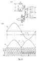
- Figs. 15A to 15C are waveform diagrams illustrating the schematic operation of the three-winding electronic transformer 3.
- a waveform on the left in Fig. 15A illustrates an input commercial AC voltage after passing through a filter F1, that is, a terminal voltage on a side of an AC input of the three-winding electronic transformer 3.
- This input waveform is subjected to high-frequency ring modulation by a half bridge circuit consisting of capacitors C1 and C2 and switches S1 and S2, as illustrated at the center of Fig. 15A, and then, is added to a primary coil N1 in a high frequency transformer HFT.
- a voltage twice a voltage generated in the secondary coil N2 is demodulated by another half bridge consisting of switches S3 and S4 and capacitors C3 and C4 (which is operated as a voltage-doubler circuit in this case).
- the switches S1 and S3 and the switches S2 and S4 are driven at the same timing.
- a sinusoidal AC waveform representing an original signal is reproduced on the side of demodulation as it is by the high frequency modulation/demodulation technique, and therefore, only the transformer is reduced in size and weight by high frequency modulation, thus enhancing the efficiency in comparison with a commercial transformer.
- a high frequency AC generated in coils N3 and N4 should be rectified by diodes D5 and D6, and then, a storage battery B can be charged by a bidirectional DC-DC converter Conv at the same time.
- a high frequency rectangular wave signal is generated by a push-pull type inverter circuit with the coils N3 and N4 and semiconductor switches S5 and S6 in the high frequency transformer HFT.
- a rectangular wave voltage generated in the coil N2 by the switches S3 and S4 becomes a DC having a double voltage value by the voltage-doubler circuit, and thus, DC power is supplied to a load Lac/dc for both of an AC and a DC. That is to say, the electronic transformer operated by the high frequency modulation/demodulation can convert the voltage irrespective of the AC and the DC.
- Fig. 15B illustrates, at the center thereof, a voltage in the high frequency transformer HFT in the case where a DC input is added to the coils N3 and N4.
- Fig. 15C illustrates one example, in which the switches S3 and S4 on the side of the secondary coil are subjected to a known PWM control so as to adjust the voltage on the side of the load.
- the AC modulation/demodulation has been illustrated, it is understood that the control should be performed in completely the same manner also in the case of the DC input.
- Figs. 13 and 14 are more specific examples of the embodiments illustrated in Figs. 7 and 8, respectively.
- the limitation of the load Lac/dc operable with both AC and DC supplies illustrated in Figs. 11 and 12 is eliminated, and thus, importance is put on integrity with existing equipment only for an AC.
- a reverse flow of the AC current can be achieved on a side of a commercial AC power source Utility from a DC source through an electronic transformer.
- Fig. 13 illustrates the case where a commercial AC power source Utility and an AC only load Lac are connected to each other via a two-winding electronic transformer 4 only on a side of a storage battery B.
- Fig. 14 illustrates the case where DC power sources WTG, PV and FC, a storage battery B and a commercial AC power source Utility and an AC only load Lac are connected to each other via a three-winding electronic transformer 5 in a mutually insulating manner.
- a great difference from the cases illustrated in Figs. 11 and 12 is in that unidirectional semiconductor switches S5 and S6 are operated at the time of both charging and discharging in the cases illustrated in Figs. 13 and 14. Furthermore, as illustrated in Figs. 9 and 10, the voltage of a storage battery and a two -phase half-wave or single-phase full-wave rectification output 6 are converted both forward and backward in the bidirectional DC-DC converter Conv, and then, AC modulation or demodulation conversion is performed in the unidirectional semiconductor switches S5 and S6, so that operation always is performed only with an AC modulation component inside of the two- winding electronic transformer 4 or the three-winding electronic transformer 5. In this manner, an AC output can be taken out at all times on the side of the AC only load irrespective of the AC power supply or the DC power supply.
- the drive pulse phase of switches S1 to S6 in the three-winding electronic transformer 5 is alternately reversed for a positive half cycle and a negative half cycle of the commercial AC power source Utility, as illustrated in, for example, Figs. 16A and 16B, so that voltages v 1 and v 2 are operated in an AC sinusoidal waveform at all times. While a DC input/output of a single-phase full-wave or two-phase half-wave is generated at a v 3 terminal in a DC circuit, an AC modulation operation can be performed with a change in magnetic flux in the three-winding electronic transformer 5, as illustrated in Fig. 15A, as described above.
- the two-winding electronic transformer 4 illustrated in Fig. 13 corresponds to that in the case where there is no coil N1 in Fig. 16, and therefore, it is understood that the other operation should be utterly the same.
- a reverse flow of the current can be achieved from the side of the storage battery onto the side of the commercial AC power source through the two-winding electronic transformer 4 and the three-winding electronic transformer 5 unless the commercial AC power source Utility fails.
- an oscillator for an inverter operation at the time of a failure should be built in the system.
- a novel co-generated power supply system in which the electric power of a natural energy system having many fluctuation factors is combined with a stable electric power such as off-peak electric power or a fuel cell, so that the stable electric power is supplied to the load via the electronic transformer commonly used at a usage rate of almost 100%, thus reducing the cost and enhancing the performance as the entire system, so as to spread and prevail the co-generated power supply and save the energy.
Landscapes
- Engineering & Computer Science (AREA)
- Power Engineering (AREA)
- Supply And Distribution Of Alternating Current (AREA)
- Charge And Discharge Circuits For Batteries Or The Like (AREA)
- Fuel Cell (AREA)
- Photovoltaic Devices (AREA)
Abstract
Description
Claims (7)
- A co-generated power supply system for delivering a co-generated power supply to a load operable with both AC and DC supplies by the use of at least one of a wind turbine generator, a solar cell and a fuel cell, a storage battery and a commercial AC power source, wherein:the wind turbine generator, the solar cell and the fuel cell are used as DC power sources, the rated voltage of each being matched to the rated voltage of the storage battery;AC power from the commercial AC power source is supplied to the load until the storage battery is fully charged by the DC power sources;DC power from the storage battery is supplied to the load when the storage battery has been fully charged; andthe AC power from the commercial AC power source is supplied to the load as the storage battery approaches the terminal period of discharging.
- A co-generated power supply system for delivering a co-generated power supply to a load operable with both AC and DC supplies either via or not via a two-winding electronic transformer by the use of at least one of a wind turbine generator, a solar cell and a fuel cell, a storage battery and a commercial AC power source, wherein:the wind turbine generator, the solar cell and the fuel cell are used as DC power sources, the rated voltage of each being matched to the rated voltage of the storage battery;the two-winding electronic transformer has two bidirectional input/output terminals for both of the AC and the DC;one of the bidirectional input/output terminals in the two-winding electronic transformer is connected to an output side of a DC power source while the other bidirectional input/output terminal is connected in a T-shaped manner between the commercial AC power source and the load;AC power from the commercial AC power source is supplied to the load not via the two-winding electronic transformer until the storage battery is fully charged by the DC power sources;DC power from the DC power sources and the storage battery is supplied to the load via the two-winding electronic transformer when the storage battery has been fully charged or the commercial AC power source fails;the electric power is replenished from the fuel cell when the storage battery is being discharged; andthe AC power is supplied to the load from the commercial AC power source in an off-peak period for the power supply, and further, the storage battery is charged by the bidirectional function and the AC/DC converting function of the two-winding electronic transformer.
- A co-generated power supply system for delivering a co-generated power supply to a load operable with both AC and DC supplies via a three-winding electronic transformer by the use of at least one of a wind turbine generator, a solar cell and a fuel cell, a storage battery and a commercial AC power source, wherein:the wind turbine generator, the solar cell and the fuel cell are used as DC power sources, the rated voltage of each being matched to the rated voltage of the storage battery;the three-winding electronic transformer has three bidirectional input/output terminals for both of the AC and the DC;the DC power sources and the storage battery, the commercial AC power source and the load are connected in a mutually insulating manner via the three-winding electronic transformer;AC power from the commercial AC power source is supplied to the load via the three-winding electronic transformer until the storage battery is fully charged by the DC power sources;DC power from the DC power sources and the storage battery is supplied to the load via the three-winding electronic transformer when the storage battery has been fully charged or the commercial AC power source fails;the electric power is replenished from the fuel cell when the storage battery is being discharged; andthe AC power from the commercial AC power source is supplied to the load in an off-peak period for the electric power supply, and further, the storage battery is charged by the bidirectional function and the AC/DC converting function of the three-winding electronic transformer.
- A co-generated power supply system for delivering a co-generated power supply to a load operable only on an AC supply either via or not via a bidirectional DC-DC converter and a two-winding electronic transformer by the use of at least one of a wind turbine generator, a solar cell and a fuel cell, a storage battery and a commercial AC power source, wherein:the wind turbine generator, the solar cell and the fuel cell are used as DC power sources, the rated voltage of each being matched to the rated voltage of the storage battery;the two-winding electronic transformer has two bidirectional input/output terminals for both of the AC and the DC and also has a high frequency transformer and modulation/demodulation semiconductor switches provided at the storage battery side and the load side of the high frequency transformer;one of the bidirectional input/output terminals in the two-winding electronic transformer is connected to an output side of the DC power source while the other bidirectional input/output terminal is connected in a T-shaped manner between the commercial AC power source and the AC only load;AC power from the commercial AC power source is supplied to the AC only load via neither the bidirectional DC-DC converter nor the two-winding electronic transformer until the storage battery is fully charged by the DC power sources;DC power from the DC power source and the storage battery is supplied to the AC only load when the storage battery has been fully charged or the commercial AC power source fails by converting the DC power from the DC power source and the storage battery into a single-phase full-wave rectification waveform by half cycle sinusoidal wave modulation in the bidirectional DC-DC converter, alternately reversing a high frequency modulation phase of two or two pairs of unidirectional semiconductor switches, which constitute the modulation/demodulation semiconductor switch disposed on the side of the storage battery in a high frequency transformer in the two-winding electronic transformer, per half cycle of a commercial frequency, and then, demodulating to take out a sinusoidal wave AC output by the modulation/demodulation semiconductor switch disposed on the side of the load in the high frequency transformer in the two-winding electronic transformer;the electric power is replenished from the fuel cell when the storage battery is being discharged;the AC power from the commercial AC power source is supplied to the AC only load in an off-peak period for the electric power supply, and further, the storage battery is charged by the bidirectional function and the AC/DC converting function of the two-winding electronic transformer and a boost type rectifying operation at a high power factor of the bidirectional DC-DC converter at the time of charging; andthe DC power is converted into the AC power by the effect of the energy bidirectional transmitting characteristics of the two-winding electronic transformer when the storage battery has been almost fully charged at a light load and the commercial AC power source does not fail, for automatic phase synchronization on the commercial AC power source side so as to achieve a reverse flow of the AC current.
- A co-generated power supply system for delivering a co-generated power supply to a load operable only on an AC supply via a bidirectional DC-DC converter and a three-winding electronic transformer by the use of at least one of a wind turbine generator, a solar cell and a fuel cell, a storage battery and a commercial AC power source, wherein:the wind turbine generator, the solar cell and the fuel cell are used as DC power sources, the rated voltage of each being matched to the rated voltage of the storage battery;the three-winding electronic transformer has three bidirectional input/output terminals for both of the AC and the DC and also has a high frequency transformer and modulation/demodulation semiconductor switches provided at the commercial AC power source side, the storage battery side and the load side of the high frequency transformer;the DC power sources, the storage battery, the commercial AC power source and the AC only load are connected in a mutually insulating manner via the three-winding electronic transformer;AC power from the commercial AC power source is supplied to the AC only load via the three-winding electronic transformer until the storage battery is fully charged by the DC power sources;DC power from the DC power sources and the storage battery is supplied to the AC only load when the storage battery has been fully charged or the commercial AC power source fails by converting the DC power from the DC power source and the storage battery into a single-phase full-wave rectification waveform by half cycle sinusoidal wave modulation in the bidirectional DC-DC converter, alternately reversing a high frequency modulation phase of two or two pairs of unidirectional semiconductor switches, which constitute the modulation/demodulation semiconductor switch disposed on the side of the storage battery in a high frequency transformer in the three-winding electronic transformer, per half cycle of a commercial frequency, and then, demodulating to take out a sinusoidal wave AC output by the modulation/demodulation semiconductor switch disposed on the side of the load in the high frequency transformer in the three-winding electronic transformer;the electric power is replenished from the fuel cell when the storage battery is being discharged;the AC power from the commercial AC power source is supplied to the AC only load in an off-peak period for the electric power supply, and fur ther, the storage battery is charged by the bidirectional function and the AC/DC converting function of the three-winding electronic transformer and a boost type rectifying operation at a high power factor of the bidirectional DC-DC converter at the time of electric charging; andthe DC power is converted into the AC power by the energy bidirectional transmitting characteristics of the three-winding electronic transformer when the storage battery has been almost fully charged at a light load and the commercial AC power source does not fail, for automatic phase synchronization on the side of the commercial AC power source so as to achieve a reverse flow of the AC current.
- The co-generated power supply system as claimed in any one of claims 1 to 5, wherein compressed hydrogen for the fuel cell can be reserved.
- A multi-source power supply system for supplying electrical power to a load, said system comprising one or more stable power sources and one or more fluctuating power sources and operable in at least two modes wherein in said first mode a or the stable power source is used to supply power to the load whilst a or the fluctuating power source charges a battery; and wherein in said second mode the battery supplies power to the load.
Applications Claiming Priority (4)
| Application Number | Priority Date | Filing Date | Title |
|---|---|---|---|
| JP2002224787 | 2002-08-01 | ||
| JP2002224787 | 2002-08-01 | ||
| JP2003280883A JP3825020B2 (en) | 2002-08-01 | 2003-07-28 | Distributed power supply system |
| JP2003280883 | 2003-07-28 |
Publications (3)
| Publication Number | Publication Date |
|---|---|
| EP1387462A2 true EP1387462A2 (en) | 2004-02-04 |
| EP1387462A3 EP1387462A3 (en) | 2007-04-11 |
| EP1387462B1 EP1387462B1 (en) | 2010-03-17 |
Family
ID=30117509
Family Applications (1)
| Application Number | Title | Priority Date | Filing Date |
|---|---|---|---|
| EP20030254832 Expired - Lifetime EP1387462B1 (en) | 2002-08-01 | 2003-08-01 | Co-generated power supply system |
Country Status (5)
| Country | Link |
|---|---|
| US (2) | US7449798B2 (en) |
| EP (1) | EP1387462B1 (en) |
| JP (1) | JP3825020B2 (en) |
| CN (1) | CN100544157C (en) |
| DE (1) | DE60331708D1 (en) |
Cited By (21)
| Publication number | Priority date | Publication date | Assignee | Title |
|---|---|---|---|---|
| WO2005099006A1 (en) * | 2004-03-31 | 2005-10-20 | Daikin Industries, Ltd. | Fuel cell power generating refrigeration system |
| NL1031646C2 (en) * | 2006-04-20 | 2007-10-23 | Nedap Nv | Modular bidirectional bus system for exchanging energy between modules. |
| US7346462B2 (en) | 2006-03-29 | 2008-03-18 | General Electric Company | System, method, and article of manufacture for determining parameter values associated with an electrical grid |
| US7378820B2 (en) | 2005-12-19 | 2008-05-27 | General Electric Company | Electrical power generation system and method for generating electrical power |
| CN100414809C (en) * | 2006-06-28 | 2008-08-27 | 贵州首朗新能源有限公司 | Intelligent Control System of Renewable Energy and Mains Power |
| EP1974435A2 (en) * | 2006-01-19 | 2008-10-01 | Renault s.a.s. | Electrical management device for vehicle power supply |
| US7505833B2 (en) | 2006-03-29 | 2009-03-17 | General Electric Company | System, method, and article of manufacture for controlling operation of an electrical power generation system |
| WO2009031002A3 (en) * | 2007-09-03 | 2009-05-07 | Energifera S R L | System for simultaneously producing electric and thermal energy |
| US20100052423A1 (en) * | 2008-09-02 | 2010-03-04 | Hitachi Computer Peripherals Co., Ltd. | Bidirectional dc-dc converter and control method thereof |
| WO2010074351A3 (en) * | 2008-12-26 | 2010-09-02 | Hitachi Koki Co., Ltd. | Charging device for portable power tool |
| EP2284973A1 (en) * | 2009-08-06 | 2011-02-16 | SMA Solar Technology AG | Reverse current sensor for solar modules connected in parallel |
| CN102484426A (en) * | 2009-09-30 | 2012-05-30 | 东芝照明技术株式会社 | DC power supply feeding system |
| CN102497001A (en) * | 2011-11-14 | 2012-06-13 | 上海新奥能源科技有限公司 | Electrical energy system and operation method thereof |
| GB2506015A (en) * | 2012-08-31 | 2014-03-19 | Grid Energy Ltd Off | Mobile Electrical Power Module |
| EP2733836A3 (en) * | 2012-11-16 | 2014-12-03 | Boltier R&D | Alternating current (AC)-direct current (DC) power booster and AC-DC power control module for AC and DC illuminations |
| CN104463342A (en) * | 2013-09-19 | 2015-03-25 | 通用电气公司 | System and method to minimize grid spinning reserve losses |
| EP2278679A3 (en) * | 2009-05-20 | 2016-03-16 | General Electric Company | Power generator distributed inverter |
| EP2698908A3 (en) * | 2012-08-14 | 2017-12-20 | Boltier R&D | AC-DC power supply device and switching mode power supply device |
| CN107785987A (en) * | 2016-08-25 | 2018-03-09 | 伊顿制造(格拉斯哥)有限合伙莫尔日分支机构 | On-Line UPS |
| CN114301079A (en) * | 2021-12-30 | 2022-04-08 | 国网湖南省电力有限公司 | Energy storage control method, equipment and medium participating in peak-shaving frequency-modulation cross application of power grid |
| EP3987651A4 (en) * | 2019-06-18 | 2023-08-02 | 10644137 Canada Inc. | Hybrid-energy apparatus, system, and method therefor |
Families Citing this family (145)
| Publication number | Priority date | Publication date | Assignee | Title |
|---|---|---|---|---|
| WO2004023625A1 (en) * | 2002-09-04 | 2004-03-18 | Hitachi, Ltd. | Power supply system and power supply method upon interruption of electric service |
| US7102251B2 (en) | 2003-08-22 | 2006-09-05 | Distributed Power, Inc. | Bi-directional multi-port inverter with high frequency link transformer |
| WO2005041384A1 (en) * | 2003-10-27 | 2005-05-06 | Mitsubishi Denki Kabushiki Kaisha | Power supply apparatus |
| US7564149B2 (en) * | 2004-07-21 | 2009-07-21 | Kasemsan Siri | Sequentially-controlled solar array power system with maximum power tracking |
| US20060071554A1 (en) * | 2004-09-27 | 2006-04-06 | Mcnamara James L | Electrical power distribution system and method thereof |
| WO2006047715A2 (en) * | 2004-10-27 | 2006-05-04 | Nextek Power Systems, Inc. | Portable hybrid applications for ac/dc load sharing |
| US20060158037A1 (en) * | 2005-01-18 | 2006-07-20 | Danley Douglas R | Fully integrated power storage and supply appliance with power uploading capability |
| JP2006217780A (en) * | 2005-02-07 | 2006-08-17 | Yamaha Motor Co Ltd | Inverter type AC power generator |
| JP2006280179A (en) * | 2005-03-30 | 2006-10-12 | Honda Motor Co Ltd | DC stabilized power supply |
| US20060261783A1 (en) * | 2005-05-23 | 2006-11-23 | Paul Gamboa | Electronic battery module (EBM) with bidirectional DC-DC converter |
| US7274975B2 (en) | 2005-06-06 | 2007-09-25 | Gridpoint, Inc. | Optimized energy management system |
| JP2007020319A (en) * | 2005-07-08 | 2007-01-25 | Yamaha Motor Co Ltd | DC power supply |
| TW200713776A (en) * | 2005-09-26 | 2007-04-01 | Hipro Electronic Co Ltd | Dual-input power supply |
| NO20054704D0 (en) * | 2005-10-13 | 2005-10-13 | Sway As | Method and method for wind turbines and propulsion systems with magnetically stable main bearing and load control system |
| US20070093280A1 (en) * | 2005-10-24 | 2007-04-26 | Mckay Christopher A | Mobile power distribution system and method thereof |
| JP5401003B2 (en) * | 2006-01-27 | 2014-01-29 | シャープ株式会社 | Solar power system |
| JP5372313B2 (en) * | 2006-02-03 | 2013-12-18 | Jx日鉱日石エネルギー株式会社 | Power supply system having fuel cell device |
| US20070228836A1 (en) * | 2006-03-30 | 2007-10-04 | Ralph Teichmann | Power generation system and method |
| US8103389B2 (en) | 2006-05-18 | 2012-01-24 | Gridpoint, Inc. | Modular energy control system |
| US20070273214A1 (en) * | 2006-05-23 | 2007-11-29 | Wang Kon-King M | System and method for connecting power sources to a power system |
| US7893346B2 (en) * | 2006-09-28 | 2011-02-22 | Jack Nachamkin | Integrated voltaic energy system |
| WO2008112592A1 (en) * | 2007-03-09 | 2008-09-18 | Anthem Orthopaedics Llc | Implantable medicament delivery device and delivery tool and method for use therewith |
| WO2009062227A1 (en) * | 2007-11-14 | 2009-05-22 | Renergyx Pty Limited | Electrical energy and distribution system |
| JP5081596B2 (en) * | 2007-12-04 | 2012-11-28 | シャープ株式会社 | Power supply system |
| US7915760B2 (en) * | 2007-12-12 | 2011-03-29 | Evans Sr Bruce Jonathan | Electric power conservation system for storing electric power for use during off-peak hours |
| US20090180765A1 (en) * | 2008-01-14 | 2009-07-16 | Ming-Hsiang Yeh | Multiple-power-selection heat storage device |
| US20090179493A1 (en) * | 2008-01-14 | 2009-07-16 | Ming-Hsiang Yeh | Power selection system for heater |
| US20090178421A1 (en) * | 2008-01-14 | 2009-07-16 | Ming-Hsiang Yeh | Air conditioning system with multiple power selections |
| US20090178423A1 (en) * | 2008-01-14 | 2009-07-16 | Ming-Hsiang Yeh | Power selection system for air conditioner |
| JP4784652B2 (en) * | 2008-02-26 | 2011-10-05 | パナソニック電工株式会社 | Power supply device |
| JP2009219310A (en) * | 2008-03-12 | 2009-09-24 | Nippon Telegr & Teleph Corp <Ntt> | Power supply device |
| WO2009124191A2 (en) * | 2008-04-02 | 2009-10-08 | Infinite Power Solutions, Inc. | Passive over/under voltage control and protection for energy storage devices associated with energy harvesting |
| TW200943668A (en) * | 2008-04-08 | 2009-10-16 | Princeton Technology Corp | Wind power charging device |
| JP4401418B2 (en) * | 2008-04-18 | 2010-01-20 | シャープ株式会社 | Bi-directional DC / DC converter and power conditioner |
| US20090284074A1 (en) * | 2008-05-19 | 2009-11-19 | Ming-Hsiang Yeh | Inverter |
| US8138624B2 (en) * | 2008-06-23 | 2012-03-20 | Ming-Hsiang Yeh | Conversion device for automobile |
| US8212406B2 (en) * | 2008-12-26 | 2012-07-03 | Yaroslav A. Pichkur | System, socket and plug apparatus for DC power distribution and usage |
| US8319373B2 (en) | 2008-12-26 | 2012-11-27 | Pichkur Yaroslav A | System, socket and plug apparatus for DC power distribution and usage |
| US20100183443A1 (en) * | 2009-01-16 | 2010-07-22 | Steve Thorne | Integrated wind turbine and solar energy collector |
| US8248230B2 (en) * | 2009-02-20 | 2012-08-21 | Redwood Systems, Inc. | Smart power device |
| CN201378812Y (en) * | 2009-02-23 | 2010-01-06 | 中山大洋电机股份有限公司 | Power supply control device and ventilation device applying same |
| US8546977B2 (en) * | 2009-04-22 | 2013-10-01 | Lsi Corporation | Voltage based switching of a power supply system current |
| KR20170132341A (en) | 2009-04-30 | 2017-12-01 | 유니버시티 오브 플로리다 리서치 파운데이션, 인크. | Single wall carbon nanotube based air cathodes |
| JP5303032B2 (en) * | 2009-06-25 | 2013-10-02 | パナソニック株式会社 | Power supply |
| JP2011015501A (en) * | 2009-06-30 | 2011-01-20 | Panasonic Electric Works Co Ltd | Power distribution system |
| US8853989B2 (en) * | 2009-07-09 | 2014-10-07 | Toyota Jidosha Kabushiki Kaisha | Fuel cell system and motor driving method |
| JP5465949B2 (en) * | 2009-08-07 | 2014-04-09 | 本田技研工業株式会社 | Power supply system |
| AP2012006150A0 (en) | 2009-09-12 | 2012-04-30 | Fenix Internat Inc | Method and apparatus for charging a battery. |
| KR101649268B1 (en) * | 2009-10-14 | 2016-08-18 | 삼성전자주식회사 | Switching mode power supply and fusing apparatus |
| EP2336835A1 (en) * | 2009-12-15 | 2011-06-22 | Siemens Aktiengesellschaft | Method and assembly for predictive controlling room temperatures in a building using cost information of different energy sources |
| KR20110080958A (en) * | 2010-01-07 | 2011-07-13 | 삼성전자주식회사 | Standby power supply method, standby power supply device, battery charging method for supplying standby power of visual display device and visual display device applying the same |
| US8575779B2 (en) | 2010-02-18 | 2013-11-05 | Alpha Technologies Inc. | Ferroresonant transformer for use in uninterruptible power supplies |
| CN101771294B (en) | 2010-03-05 | 2012-08-15 | 矽力杰半导体技术(杭州)有限公司 | Integrated drive control circuit and control method thereof |
| JP5110110B2 (en) | 2010-03-18 | 2012-12-26 | 株式会社デンソー | Vehicle power supply |
| CN102223136A (en) * | 2010-04-15 | 2011-10-19 | 冬雷 | Non-energy-storing motor-driven system for complementary power supply of wind power generation and electrical network |
| US20110278932A1 (en) * | 2010-05-13 | 2011-11-17 | Eaton Corporation | Uninterruptible power supply systems and methods using isolated interface for variably available power source |
| US20120074786A1 (en) | 2010-05-13 | 2012-03-29 | Eaton Corporation | Uninterruptible power supply systems and methods using isolated interface for variably available power source |
| US11404880B2 (en) * | 2010-05-28 | 2022-08-02 | Christopher Pawlik | Systems and methods for generating and conserving power |
| US9793752B1 (en) * | 2010-06-28 | 2017-10-17 | Amazon Technologies, Inc. | Reserve power system for data center |
| CN101892959B (en) * | 2010-08-16 | 2012-05-23 | 李绪祯 | Portable wind-power and solar photovoltaic complementary power station |
| US8812164B2 (en) * | 2010-10-12 | 2014-08-19 | Engineered Electric Company | Portable cogeneration system incorporating renewable energy sources |
| US8957543B2 (en) | 2010-10-15 | 2015-02-17 | Nextek Power Systems, Inc. | Arrangement for and method of dynamically managing electrical power between an electrical power source and an electrical load |
| US9660471B2 (en) | 2010-10-15 | 2017-05-23 | Nextek Power Systems, Inc. | Arrangement for and method of dynamically managing electrical power between an electrical power source and an electrical load |
| US9030048B2 (en) * | 2010-10-18 | 2015-05-12 | Alpha Technologies Inc. | Uninterruptible power supply systems and methods for communications systems |
| US9774198B2 (en) * | 2010-11-08 | 2017-09-26 | Brandon Culver | Wind and solar powered heat trace with homeostatic control |
| WO2012063409A1 (en) | 2010-11-10 | 2012-05-18 | パナソニック株式会社 | Operation planning method, operation planning device, method for operating heat pump hot-water supply system, and method for operating heat pump hot-water supply and heating system |
| RU2013132367A (en) * | 2010-12-17 | 2015-01-27 | Юниверсити Оф Флорида Рисеч Фаундэйшн, Инк. | OXIDATION AND GENERATION OF HYDROGEN ON CARBON FILMS |
| CN102687364A (en) * | 2010-12-27 | 2012-09-19 | 松下电器产业株式会社 | Operation planning method and method for operating heat-pump hot-water supply heating system |
| TW201228173A (en) * | 2010-12-29 | 2012-07-01 | Chung Hsin Elec & Mach Mfg | Power supply system and fuel cell backup power system thereof |
| CA2825483C (en) | 2011-01-23 | 2019-11-12 | Alpha Technologies Services, Inc. | Switching systems and methods for use in uninterruptible power supplies |
| CN102638061B (en) * | 2011-02-12 | 2014-12-03 | 中国人民解放军总后勤部建筑工程研究所 | General charging controller for wind-light-diesel combined power supply system and control method thereof |
| SG193937A1 (en) | 2011-04-04 | 2013-11-29 | Univ Florida | Nanotube dispersants and dispersant free nanotube films therefrom |
| CN102185373A (en) * | 2011-05-19 | 2011-09-14 | 珠海泰坦科技股份有限公司 | Distributed DC uninterrupted power supply system |
| KR101243192B1 (en) | 2011-08-02 | 2013-03-25 | 한국전기연구원 | Method and System for controlling output of wind power generation equipment |
| DE102011080996B4 (en) * | 2011-08-16 | 2024-02-15 | Tridonic Gmbh & Co Kg | Operation of a lamp with autonomous energy storage |
| US9037443B1 (en) | 2011-10-16 | 2015-05-19 | Alpha Technologies Inc. | Systems and methods for solar power equipment |
| JP5578161B2 (en) * | 2011-11-29 | 2014-08-27 | 株式会社安川電機 | Power system |
| CN102624073B (en) * | 2012-03-31 | 2014-06-04 | 天津海腾太阳能科技有限公司 | Solar inverter power supply |
| US9627905B2 (en) * | 2012-05-04 | 2017-04-18 | Jesse Green | Jumper cable |
| US9876375B2 (en) * | 2012-05-04 | 2018-01-23 | Jesse Green | Jumper cable |
| US9234916B2 (en) | 2012-05-11 | 2016-01-12 | Alpha Technologies Inc. | Status monitoring cables for generators |
| CN102810857B (en) * | 2012-07-09 | 2014-10-29 | 华中科技大学 | Power quality regulator for series direct current power system |
| KR20140023125A (en) | 2012-08-17 | 2014-02-26 | 엘지전자 주식회사 | Energy storage device, device for managing power, mobile termianl and method for operating the same |
| JP6103874B2 (en) * | 2012-10-12 | 2017-03-29 | 株式会社日立情報通信エンジニアリング | Power supply device and its operation method |
| US9711967B1 (en) * | 2012-11-06 | 2017-07-18 | Reliance Conrtols Corporation | Off grid backup inverter automatic transfer switch |
| CN103825294A (en) * | 2012-11-19 | 2014-05-28 | 周锡卫 | Energy storage inverter suitable for distributed new energy electric power |
| CN103023320B (en) | 2012-11-23 | 2014-09-03 | 矽力杰半导体技术(杭州)有限公司 | High-efficiency bidirectional direct current converter and control method thereof |
| GB2516414A (en) * | 2013-05-28 | 2015-01-28 | Meb Engineering & Commercial Services Ltd | Residential Domestic Uninterruptable Power Supply |
| CN103414360B (en) * | 2013-07-31 | 2015-10-28 | 邱志锋 | Combination switch power supply |
| US20160233679A1 (en) * | 2013-10-18 | 2016-08-11 | State Grid Corporation Of China | A method and system for control of smoothing the energy storage in wind phtovolatic power fluctuation based on changing rate |
| JP2017504547A (en) | 2013-11-20 | 2017-02-09 | ユニバーシティー オブ フロリダ リサーチ ファウンデーション,インコーポレイテッドUniversity Of Florida Research Foundation,Inc. | Reduction of carbon dioxide with carbon-containing materials |
| US9871406B1 (en) | 2013-12-18 | 2018-01-16 | Amazon Technologies, Inc. | Reserve power system transfer switches for data center |
| BR112018004887A2 (en) | 2015-09-13 | 2018-10-09 | Alpha Technologies Inc. | power control systems and methods. |
| US10381867B1 (en) | 2015-10-16 | 2019-08-13 | Alpha Technologeis Services, Inc. | Ferroresonant transformer systems and methods with selectable input and output voltages for use in uninterruptible power supplies |
| CN107069978B (en) | 2015-12-03 | 2022-06-28 | 松下知识产权经营株式会社 | Converters and Controllers |
| JP6817563B2 (en) * | 2015-12-14 | 2021-01-20 | パナソニックIpマネジメント株式会社 | Power transmission system and controller |
| US20170187200A1 (en) * | 2015-12-28 | 2017-06-29 | Dialog Semiconductor (Uk) Limited | Charger Communication by Load Modulation |
| CN107046370B (en) | 2016-02-09 | 2020-05-26 | 松下知识产权经营株式会社 | Converter, power transmission system and controller |
| CN107046379B (en) | 2016-02-09 | 2020-07-10 | 松下知识产权经营株式会社 | Converter, power transmission system and controller |
| CN107294414B (en) | 2016-04-08 | 2020-09-18 | 松下知识产权经营株式会社 | Power conversion device |
| CN106026152B (en) * | 2016-05-19 | 2017-06-06 | 合肥工业大学 | A kind of electric automobile accesses the discharge and recharge dispatching method of micro-capacitance sensor |
| CN107437889B (en) | 2016-05-26 | 2020-06-12 | 松下知识产权经营株式会社 | Power conversion circuit and power transmission system |
| US20200057098A1 (en) * | 2016-11-15 | 2020-02-20 | Electrolux Appliances Aktiebolag | Monitoring arrangement for domestic or commercial electrical appliances |
| CN106786532B (en) * | 2016-12-27 | 2023-11-14 | 爱恒能源科技(上海)有限公司 | Intelligent power optimization distributor |
| CN106602554B (en) * | 2016-12-27 | 2019-08-02 | 爱恒能源科技(上海)有限公司 | A Method for Intelligent Optimal Distribution of Electric Power |
| CA3069966A1 (en) | 2017-07-14 | 2019-01-17 | Alpha Technologies Services, Inc. | Voltage regulated ac power supply systems and methods |
| US12199466B2 (en) * | 2017-08-25 | 2025-01-14 | Schneider Electric It Corporation | Uninterruptible power supply system and method |
| US11342833B2 (en) * | 2017-10-25 | 2022-05-24 | Hubbell Incorporated | Switch for a lighting system |
| US11332030B2 (en) | 2018-07-03 | 2022-05-17 | Daihen Corporation | Power system interconnection system, and method of installing power system interconnection system |
| EP3626489A1 (en) | 2018-09-19 | 2020-03-25 | Thermo King Corporation | Methods and systems for energy management of a transport climate control system |
| EP3626490A1 (en) | 2018-09-19 | 2020-03-25 | Thermo King Corporation | Methods and systems for power and load management of a transport climate control system |
| US11034213B2 (en) | 2018-09-29 | 2021-06-15 | Thermo King Corporation | Methods and systems for monitoring and displaying energy use and energy cost of a transport vehicle climate control system or a fleet of transport vehicle climate control systems |
| US11273684B2 (en) | 2018-09-29 | 2022-03-15 | Thermo King Corporation | Methods and systems for autonomous climate control optimization of a transport vehicle |
| CN111010038B (en) * | 2018-10-05 | 2024-10-18 | 株式会社电装 | Power conversion equipment |
| JP7353008B2 (en) * | 2018-10-05 | 2023-09-29 | 株式会社デンソー | power converter |
| US10870333B2 (en) | 2018-10-31 | 2020-12-22 | Thermo King Corporation | Reconfigurable utility power input with passive voltage booster |
| US10926610B2 (en) | 2018-10-31 | 2021-02-23 | Thermo King Corporation | Methods and systems for controlling a mild hybrid system that powers a transport climate control system |
| US11059352B2 (en) | 2018-10-31 | 2021-07-13 | Thermo King Corporation | Methods and systems for augmenting a vehicle powered transport climate control system |
| US10875497B2 (en) | 2018-10-31 | 2020-12-29 | Thermo King Corporation | Drive off protection system and method for preventing drive off |
| US11022451B2 (en) | 2018-11-01 | 2021-06-01 | Thermo King Corporation | Methods and systems for generation and utilization of supplemental stored energy for use in transport climate control |
| US11554638B2 (en) | 2018-12-28 | 2023-01-17 | Thermo King Llc | Methods and systems for preserving autonomous operation of a transport climate control system |
| EP3906174B1 (en) | 2018-12-31 | 2024-05-29 | Thermo King LLC | Methods and systems for providing feedback for a transport climate control system |
| EP3906175A1 (en) | 2018-12-31 | 2021-11-10 | Thermo King Corporation | Methods and systems for providing predictive energy consumption feedback for powering a transport climate control system using external data |
| US11072321B2 (en) | 2018-12-31 | 2021-07-27 | Thermo King Corporation | Systems and methods for smart load shedding of a transport vehicle while in transit |
| ES2982673T3 (en) | 2018-12-31 | 2024-10-17 | Thermo King Llc | Methods and systems for reporting and mitigating a suboptimal event occurring in a transport HVAC control system |
| EP3906173B1 (en) | 2018-12-31 | 2024-05-22 | Thermo King LLC | Methods and systems for providing predictive energy consumption feedback for powering a transport climate control system |
| US11135931B2 (en) * | 2019-05-28 | 2021-10-05 | GM Global Technology Operations LLC | System for charging a battery electric vehicle or a plugin hybrid vehicle using a mobile fuel cell |
| EP3756914B1 (en) | 2019-06-28 | 2023-09-27 | Thermo King LLC | Climate controlled vehicle, transport climate control equipment, method of retrofitting a vehicle and method of operation |
| US12107457B2 (en) * | 2019-09-02 | 2024-10-01 | Ravisekhar Nadimpalli Raju | System to provide AC or DC power to electronic equipment |
| US11214118B2 (en) | 2019-09-09 | 2022-01-04 | Thermo King Corporation | Demand-side power distribution management for a plurality of transport climate control systems |
| US11376922B2 (en) | 2019-09-09 | 2022-07-05 | Thermo King Corporation | Transport climate control system with a self-configuring matrix power converter |
| CN112467720A (en) | 2019-09-09 | 2021-03-09 | 冷王公司 | Optimized power distribution for a transport climate control system between one or more power supply stations |
| US11203262B2 (en) | 2019-09-09 | 2021-12-21 | Thermo King Corporation | Transport climate control system with an accessory power distribution unit for managing transport climate control loads |
| US11135894B2 (en) | 2019-09-09 | 2021-10-05 | Thermo King Corporation | System and method for managing power and efficiently sourcing a variable voltage for a transport climate control system |
| ES2992855T3 (en) | 2019-09-09 | 2024-12-19 | Thermo King Llc | Prioritized power delivery for facilitating transport climate control |
| US11420495B2 (en) | 2019-09-09 | 2022-08-23 | Thermo King Corporation | Interface system for connecting a vehicle and a transport climate control system |
| US10985511B2 (en) | 2019-09-09 | 2021-04-20 | Thermo King Corporation | Optimized power cord for transferring power to a transport climate control system |
| US11458802B2 (en) | 2019-09-09 | 2022-10-04 | Thermo King Corporation | Optimized power management for a transport climate control energy source |
| US11489431B2 (en) | 2019-12-30 | 2022-11-01 | Thermo King Corporation | Transport climate control system power architecture |
| US11287868B1 (en) | 2020-07-15 | 2022-03-29 | Amazon Technologies, Inc. | Facility power backstopping system for power monitoring and power loss prevention |
| MA64632B2 (en) * | 2021-08-17 | 2025-08-29 | Envision Energy Co., Ltd. | EMERGENCY POWER SUPPLY AND ITS OPERATING METHOD |
| CN116937658A (en) * | 2022-03-31 | 2023-10-24 | 中国电力科学研究院有限公司 | Mobile integrated hydrogen energy power supply guarantee system and method |
| DE102022116671A1 (en) * | 2022-07-04 | 2024-01-04 | Sma Solar Technology Ag | POWER CONVERTER, METHOD FOR OPERATING A POWER CONVERTER AND SYSTEM COMPRISING A DC ENERGY SOURCE, A DC NETWORK AND A POWER CONVERTER |
| FR3144436B1 (en) * | 2022-12-22 | 2025-01-10 | Commissariat Energie Atomique | Uninterruptible Power Supply Circuit |
| LU508591B1 (en) * | 2024-10-18 | 2026-04-20 | Skeleton Tech Gmbh | Auxiliary redundant power supply for an energy storage system and energy storage system |
Family Cites Families (16)
| Publication number | Priority date | Publication date | Assignee | Title |
|---|---|---|---|---|
| US5172009A (en) * | 1991-02-25 | 1992-12-15 | Regents Of The University Of Minnesota | Standby power supply with load-current harmonics neutralizer |
| JPH06141469A (en) | 1992-10-27 | 1994-05-20 | Syst Pointo:Kk | Hybrid switchboard |
| JP3029185B2 (en) * | 1994-04-12 | 2000-04-04 | キヤノン株式会社 | Islanding prevention device, distributed power generation device and power generation system using the same |
| JPH0951638A (en) * | 1995-08-03 | 1997-02-18 | Japan Storage Battery Co Ltd | Distributed power supply |
| WO1997047070A1 (en) * | 1996-06-06 | 1997-12-11 | I-Hits Laboratory Corporation | Ac/ac converter |
| JP3805844B2 (en) * | 1996-12-05 | 2006-08-09 | 株式会社アイ・ヒッツ研究所 | Uninterruptible power supply |
| US6198178B1 (en) * | 1999-12-21 | 2001-03-06 | International Power Systems, Inc. | Step wave power converter |
| US6184593B1 (en) * | 1999-07-29 | 2001-02-06 | Abb Power T&D Company Inc. | Uninterruptible power supply |
| AU2001271241A1 (en) * | 2000-03-20 | 2001-10-03 | Alpha Technologies, Inc. | Uninterruptible power supplies employing fuel cells |
| US6522955B1 (en) * | 2000-07-28 | 2003-02-18 | Metallic Power, Inc. | System and method for power management |
| DE10044096A1 (en) * | 2000-09-07 | 2002-04-04 | Aloys Wobben | Off-grid and method for operating an off-grid |
| US6639328B2 (en) * | 2000-12-19 | 2003-10-28 | Capstone Turbine Corporation | Microturbine/capacitor power distribution system |
| JP4570245B2 (en) * | 2000-12-27 | 2010-10-27 | シャープ株式会社 | Distributed power system |
| US6630622B2 (en) * | 2001-01-15 | 2003-10-07 | Annemarie Hvistendahl Konold | Combined solar electric power and liquid heat transfer collector panel |
| US20040044442A1 (en) * | 2001-12-28 | 2004-03-04 | Bayoumi Deia Salah-Eldin | Optimized dispatch planning of distributed resources in electrical power systems |
| US20030160454A1 (en) * | 2002-02-25 | 2003-08-28 | John Manolis | Renewabel gravity, wind and solar energy engine |
-
2003
- 2003-07-28 JP JP2003280883A patent/JP3825020B2/en not_active Expired - Lifetime
- 2003-07-31 US US10/630,692 patent/US7449798B2/en not_active Expired - Fee Related
- 2003-08-01 EP EP20030254832 patent/EP1387462B1/en not_active Expired - Lifetime
- 2003-08-01 DE DE60331708T patent/DE60331708D1/en not_active Expired - Lifetime
- 2003-08-01 CN CNB031525393A patent/CN100544157C/en not_active Expired - Fee Related
-
2008
- 2008-09-15 US US12/232,308 patent/US20090085404A1/en not_active Abandoned
Cited By (36)
| Publication number | Priority date | Publication date | Assignee | Title |
|---|---|---|---|---|
| WO2005099006A1 (en) * | 2004-03-31 | 2005-10-20 | Daikin Industries, Ltd. | Fuel cell power generating refrigeration system |
| US7614245B2 (en) | 2004-03-31 | 2009-11-10 | Daikin Industries, Ltd. | Fuel cell power generation refrigerating system |
| US7560906B2 (en) | 2005-12-19 | 2009-07-14 | General Electric Company | Electrical power generation system |
| EP1798837A3 (en) * | 2005-12-19 | 2015-12-09 | General Electric Company | Electrical power generation system and method for generating electrical power |
| US7378820B2 (en) | 2005-12-19 | 2008-05-27 | General Electric Company | Electrical power generation system and method for generating electrical power |
| EP1974435A2 (en) * | 2006-01-19 | 2008-10-01 | Renault s.a.s. | Electrical management device for vehicle power supply |
| CN101047316B (en) * | 2006-03-29 | 2012-01-11 | 通用电气公司 | System, method, and article for determining parameter values associated with an electrical grid |
| US7346462B2 (en) | 2006-03-29 | 2008-03-18 | General Electric Company | System, method, and article of manufacture for determining parameter values associated with an electrical grid |
| US7505833B2 (en) | 2006-03-29 | 2009-03-17 | General Electric Company | System, method, and article of manufacture for controlling operation of an electrical power generation system |
| EP1848085A3 (en) * | 2006-04-20 | 2010-01-13 | N.V. Nederlandsche Apparatenfabriek NEDAP | Modular bidirectional bus system for exchanging energy between modules |
| NL1031646C2 (en) * | 2006-04-20 | 2007-10-23 | Nedap Nv | Modular bidirectional bus system for exchanging energy between modules. |
| CN100414809C (en) * | 2006-06-28 | 2008-08-27 | 贵州首朗新能源有限公司 | Intelligent Control System of Renewable Energy and Mains Power |
| WO2009031002A3 (en) * | 2007-09-03 | 2009-05-07 | Energifera S R L | System for simultaneously producing electric and thermal energy |
| US20100052423A1 (en) * | 2008-09-02 | 2010-03-04 | Hitachi Computer Peripherals Co., Ltd. | Bidirectional dc-dc converter and control method thereof |
| EP2159908A3 (en) * | 2008-09-02 | 2011-09-14 | Hitachi Computer Peripherals Co., Ltd. | Bidirectional DC-DC converter and control method thereof |
| TWI401875B (en) * | 2008-09-02 | 2013-07-11 | Hitachi Comp Peripherals Co | Bidirectional DC - DC converter and its control method |
| TWI497893B (en) * | 2008-09-02 | 2015-08-21 | Hitachi Info & Telecomm Eng | Bidirectional DC - DC converter and its control method |
| US8629661B2 (en) | 2008-09-02 | 2014-01-14 | Hitachi Information & Telecommunication Engineering, Ltd. | Bidirectional DC-DC converter and control method thereof |
| US8378646B2 (en) | 2008-09-02 | 2013-02-19 | Hitachi Computer Peripherals Co., Ltd. | Bidirectional dc-dc converter and control method thereof |
| WO2010074351A3 (en) * | 2008-12-26 | 2010-09-02 | Hitachi Koki Co., Ltd. | Charging device for portable power tool |
| EP2278679A3 (en) * | 2009-05-20 | 2016-03-16 | General Electric Company | Power generator distributed inverter |
| CN102484368A (en) * | 2009-08-06 | 2012-05-30 | 艾思玛太阳能技术股份公司 | Reverse current sensor |
| EP2284973A1 (en) * | 2009-08-06 | 2011-02-16 | SMA Solar Technology AG | Reverse current sensor for solar modules connected in parallel |
| WO2011015476A3 (en) * | 2009-08-06 | 2012-02-02 | Sma Solar Technology Ag | Reverse current sensor |
| CN102484368B (en) * | 2009-08-06 | 2015-07-22 | 艾思玛太阳能技术股份公司 | Reverse current sensor |
| CN102484426A (en) * | 2009-09-30 | 2012-05-30 | 东芝照明技术株式会社 | DC power supply feeding system |
| CN102484426B (en) * | 2009-09-30 | 2015-05-13 | 东芝照明技术株式会社 | DC power supply feeding system |
| CN102497001A (en) * | 2011-11-14 | 2012-06-13 | 上海新奥能源科技有限公司 | Electrical energy system and operation method thereof |
| EP2698908A3 (en) * | 2012-08-14 | 2017-12-20 | Boltier R&D | AC-DC power supply device and switching mode power supply device |
| EP3780372A1 (en) * | 2012-08-14 | 2021-02-17 | Boltier R&D | Ac-dc switching mode power supply device |
| GB2506015A (en) * | 2012-08-31 | 2014-03-19 | Grid Energy Ltd Off | Mobile Electrical Power Module |
| EP2733836A3 (en) * | 2012-11-16 | 2014-12-03 | Boltier R&D | Alternating current (AC)-direct current (DC) power booster and AC-DC power control module for AC and DC illuminations |
| CN104463342A (en) * | 2013-09-19 | 2015-03-25 | 通用电气公司 | System and method to minimize grid spinning reserve losses |
| CN107785987A (en) * | 2016-08-25 | 2018-03-09 | 伊顿制造(格拉斯哥)有限合伙莫尔日分支机构 | On-Line UPS |
| EP3987651A4 (en) * | 2019-06-18 | 2023-08-02 | 10644137 Canada Inc. | Hybrid-energy apparatus, system, and method therefor |
| CN114301079A (en) * | 2021-12-30 | 2022-04-08 | 国网湖南省电力有限公司 | Energy storage control method, equipment and medium participating in peak-shaving frequency-modulation cross application of power grid |
Also Published As
| Publication number | Publication date |
|---|---|
| US7449798B2 (en) | 2008-11-11 |
| CN100544157C (en) | 2009-09-23 |
| CN1494190A (en) | 2004-05-05 |
| EP1387462A3 (en) | 2007-04-11 |
| US20090085404A1 (en) | 2009-04-02 |
| JP2004080987A (en) | 2004-03-11 |
| EP1387462B1 (en) | 2010-03-17 |
| DE60331708D1 (en) | 2010-04-29 |
| US20040066094A1 (en) | 2004-04-08 |
| JP3825020B2 (en) | 2006-09-20 |
Similar Documents
| Publication | Publication Date | Title |
|---|---|---|
| EP1387462B1 (en) | Co-generated power supply system | |
| US8106535B2 (en) | Power conditioner | |
| US5929538A (en) | Multimode power processor | |
| US20050105224A1 (en) | Inverter apparatus connected to a plurality of direct current power sources and dispersed-power-source system having inverter apparatus linked to commercial power system to operate | |
| US12160137B2 (en) | Online interactive uninterruptible power supply and method for control thereof | |
| JP5290349B2 (en) | DC power supply system and control method thereof | |
| Ryu et al. | Test bed implementation of 380V DC distribution system using isolated bidirectional power converters | |
| WO2002005403A1 (en) | Grid-linked power supply | |
| JP4180086B2 (en) | Distributed power supply system | |
| KR102379157B1 (en) | Integrated dc/dc and ac/dc converter system | |
| JP2008283841A (en) | Dc voltage power supply system for residence | |
| US11811329B2 (en) | Remotely programmable multi mode bidirectional power converter | |
| Vinusha et al. | Improved power quality of single phase on-board charger with wide voltage conversion range | |
| KR101162221B1 (en) | An apparatus of preventing over-charging/over-discharging for an energy storage and a method thereof | |
| JP3810887B2 (en) | Auxiliary power supply combined power supply system | |
| KR200485327Y1 (en) | Stand-alone and grid-connected type photovoltaic power generator using low-voltage battery | |
| Rawabi | Design and Development of Bridge-less PFC Converter based EV charger | |
| GB2189097A (en) | Solar power systems | |
| JP2746136B2 (en) | DC power supply | |
| CN222888060U (en) | Green energy storage and circulation high-precision bidirectional converter | |
| KR101458467B1 (en) | Resonant battery charging device, charging method thereof and self generator including the same | |
| US20260058485A1 (en) | Devices, systems, and methods for connecting a direct-current energy storage to an alternating current load | |
| Karthick et al. | Battery Management In Grid Into Vehicle Integration For Smart Electric Vehicles | |
| Sharmela et al. | Interleaved Luo Converter-Fed Electric Vehicle Battery Charger Integrated with Renewable Energy | |
| JPH04308432A (en) | Dc power supply system |
Legal Events
| Date | Code | Title | Description |
|---|---|---|---|
| PUAI | Public reference made under article 153(3) epc to a published international application that has entered the european phase |
Free format text: ORIGINAL CODE: 0009012 |
|
| AK | Designated contracting states |
Kind code of ref document: A2 Designated state(s): AT BE BG CH CY CZ DE DK EE ES FI FR GB GR HU IE IT LI LU MC NL PT RO SE SI SK TR |
|
| AX | Request for extension of the european patent |
Extension state: AL LT LV MK |
|
| PUAL | Search report despatched |
Free format text: ORIGINAL CODE: 0009013 |
|
| AK | Designated contracting states |
Kind code of ref document: A3 Designated state(s): AT BE BG CH CY CZ DE DK EE ES FI FR GB GR HU IE IT LI LU MC NL PT RO SE SI SK TR |
|
| AX | Request for extension of the european patent |
Extension state: AL LT LV MK |
|
| RAP1 | Party data changed (applicant data changed or rights of an application transferred) |
Owner name: I-HITS LABORATORY |
|
| 17P | Request for examination filed |
Effective date: 20070727 |
|
| 17Q | First examination report despatched |
Effective date: 20070926 |
|
| AKX | Designation fees paid |
Designated state(s): DE FR GB |
|
| GRAP | Despatch of communication of intention to grant a patent |
Free format text: ORIGINAL CODE: EPIDOSNIGR1 |
|
| GRAS | Grant fee paid |
Free format text: ORIGINAL CODE: EPIDOSNIGR3 |
|
| GRAA | (expected) grant |
Free format text: ORIGINAL CODE: 0009210 |
|
| AK | Designated contracting states |
Kind code of ref document: B1 Designated state(s): DE FR GB |
|
| REG | Reference to a national code |
Ref country code: GB Ref legal event code: FG4D |
|
| REF | Corresponds to: |
Ref document number: 60331708 Country of ref document: DE Date of ref document: 20100429 Kind code of ref document: P |
|
| PLBE | No opposition filed within time limit |
Free format text: ORIGINAL CODE: 0009261 |
|
| STAA | Information on the status of an ep patent application or granted ep patent |
Free format text: STATUS: NO OPPOSITION FILED WITHIN TIME LIMIT |
|
| 26N | No opposition filed |
Effective date: 20101220 |
|
| GBPC | Gb: european patent ceased through non-payment of renewal fee |
Effective date: 20100801 |
|
| REG | Reference to a national code |
Ref country code: FR Ref legal event code: ST Effective date: 20110502 |
|
| REG | Reference to a national code |
Ref country code: DE Ref legal event code: R119 Ref document number: 60331708 Country of ref document: DE Effective date: 20110301 |
|
| PG25 | Lapsed in a contracting state [announced via postgrant information from national office to epo] |
Ref country code: FR Free format text: LAPSE BECAUSE OF NON-PAYMENT OF DUE FEES Effective date: 20100831 Ref country code: DE Free format text: LAPSE BECAUSE OF NON-PAYMENT OF DUE FEES Effective date: 20110301 |
|
| PG25 | Lapsed in a contracting state [announced via postgrant information from national office to epo] |
Ref country code: GB Free format text: LAPSE BECAUSE OF NON-PAYMENT OF DUE FEES Effective date: 20100801 |