EP1387443A1 - Umrichtersystem - Google Patents
Umrichtersystem Download PDFInfo
- Publication number
- EP1387443A1 EP1387443A1 EP03012889A EP03012889A EP1387443A1 EP 1387443 A1 EP1387443 A1 EP 1387443A1 EP 03012889 A EP03012889 A EP 03012889A EP 03012889 A EP03012889 A EP 03012889A EP 1387443 A1 EP1387443 A1 EP 1387443A1
- Authority
- EP
- European Patent Office
- Prior art keywords
- modules
- electrical
- inverter system
- plate
- module
- Prior art date
- Legal status (The legal status is an assumption and is not a legal conclusion. Google has not performed a legal analysis and makes no representation as to the accuracy of the status listed.)
- Granted
Links
- 238000010292 electrical insulation Methods 0.000 claims description 4
- 238000002955 isolation Methods 0.000 claims description 3
- 238000006073 displacement reaction Methods 0.000 claims description 2
- 239000011888 foil Substances 0.000 claims description 2
- 238000001746 injection moulding Methods 0.000 claims 1
- 239000004020 conductor Substances 0.000 description 3
- 238000005516 engineering process Methods 0.000 description 2
- 238000005452 bending Methods 0.000 description 1
- 230000015572 biosynthetic process Effects 0.000 description 1
- 239000002131 composite material Substances 0.000 description 1
- 238000003780 insertion Methods 0.000 description 1
- 230000037431 insertion Effects 0.000 description 1
- 238000004519 manufacturing process Methods 0.000 description 1
- 239000007769 metal material Substances 0.000 description 1
- 238000000034 method Methods 0.000 description 1
- 238000003825 pressing Methods 0.000 description 1
- 238000007639 printing Methods 0.000 description 1
Images


Classifications
-
- H—ELECTRICITY
- H01—ELECTRIC ELEMENTS
- H01R—ELECTRICALLY-CONDUCTIVE CONNECTIONS; STRUCTURAL ASSOCIATIONS OF A PLURALITY OF MUTUALLY-INSULATED ELECTRICAL CONNECTING ELEMENTS; COUPLING DEVICES; CURRENT COLLECTORS
- H01R13/00—Details of coupling devices of the kinds covered by groups H01R12/70 or H01R24/00 - H01R33/00
- H01R13/02—Contact members
- H01R13/22—Contacts for co-operating by abutting
- H01R13/24—Contacts for co-operating by abutting resilient; resiliently-mounted
- H01R13/2464—Contacts for co-operating by abutting resilient; resiliently-mounted characterized by the contact point
- H01R13/2492—Contacts for co-operating by abutting resilient; resiliently-mounted characterized by the contact point multiple contact points
-
- H—ELECTRICITY
- H02—GENERATION; CONVERSION OR DISTRIBUTION OF ELECTRIC POWER
- H02M—APPARATUS FOR CONVERSION BETWEEN AC AND AC, BETWEEN AC AND DC, OR BETWEEN DC AND DC, AND FOR USE WITH MAINS OR SIMILAR POWER SUPPLY SYSTEMS; CONVERSION OF DC OR AC INPUT POWER INTO SURGE OUTPUT POWER; CONTROL OR REGULATION THEREOF
- H02M7/00—Conversion of AC power input into DC power output; Conversion of DC power input into AC power output
- H02M7/003—Constructional details, e.g. physical layout, assembly, wiring or busbar connections
Definitions
- the invention relates to a converter system.
- the MOVIDYN converter system which includes supply modules and axis modules.
- the DC intermediate circuit hereinafter also referred to as GSZ, connected to the power supply of the axis modules. It comprises three power rails.
- the invention has the object of developing a converter system, the inexpensive to produce and quick and easy to install and connect.
- the object in the converter system according to claim 1 in claim 1 solved characteristics.
- At least one Supply module VM and at least one axle module AM is included, wherein the modules electrical first connection devices for low voltage and signal connections for having electrical leads for, wherein the modules further connection devices for having electrical lines for power, wherein for the manufacture of electrical Low voltage and signal connections between adjacent modules of each module a connection plate comprising the exposed portions of electrical traces such that with suitable displacement and / or positioning of the Connecting plate, the first connection devices with the exposed areas in electrical contact can be brought.
- the advantage here is that the inverter system cost-effectively and quickly and easily Easy to install and connect because of the connection plate.
- a novel arrangement of amaschineticianstechnik via spring contacts and a novel arrangement of a connecting plate is provided. It will be easy and inexpensive to use parts, whereby the inverter system also is inexpensive to produce. In particular, to comply with electrical directives, For example, UL, very inexpensive plastic parts used.
- the first connection devices are with the exposed areas by means of clamping elements and / or a pressure plate in electrical Contactable.
- the advantage here is that only a few parts are necessary, even can be manufactured easily and inexpensively.
- the DC voltage intermediate circuit is used for Power supply of the modules.
- the advantage here is that a single supply module can supply several modules via the DC voltage intermediate circuit. Thus falls in the Compared to versions with independent individual inverters a corresponding number away from rectifiers.
- the clamping elements and / or pressure plate for electrical insulation and / or compliance with electrical regulations designed and used.
- the advantage here is that they not only the mechanical but also have electrical function, in particular shielding electromagnetic waves.
- the modules each have a cover for electrical insulation of the further connection devices for electrical cables for Power on and it is the cover also for the first connection devices provided, in particular for the isolation and / or compliance with electrical regulations.
- the advantage here is that for the power connection devices anyway necessary cover can also be used for NSV connection devices, in particular for the isolation, shielding of electromagnetic waves and like.
- connection of the NSV with the connection unit offers the advantage that the necessary Cover the connection unit due to the high voltages at the same time advantageous for Compliance with other electrical regulations may be used for the NSV.
- the invention shows an inverter system between feed and axis modules necessary connection technology for a DC intermediate circuit (GSZ) as well as for Low-voltage and signal connections (NSV) in a cost-saving manner.
- GSZ DC intermediate circuit
- NSV Low-voltage and signal connections
- FIG. 1 is a first exemplary Inverter system shown in which a feed module or supply module VM and several axis modules AM are provided side by side.
- the supply module VM feeds the DC intermediate circuit (DC), which is used to supply the power Achsmodule AM is electrically connected to these, the axis modules Have converter functionality and connected by means of motor supply lines 3 Electric motors M supply.
- DC DC intermediate circuit
- the electrical cables of the DC intermediate circuit are as Busbars or cables or strands vorsehbar, the modules corresponding Connecting devices, such as plugs or screw connections have.
- the GSZ includes three lines in this example.
- As low voltage and signal connections (NSV) between supply or infeed and axis modules is another Connection technology provided.
- connection unit 1 is provided for NSV and the connection unit 2 for GSZ.
- FIG. 2 is a side view is sketched.
- Figure 3 is a front view is sketched.
- Figure 4 is a plan view is sketched.
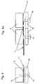
- FIG. 4 a is a plan view of two connection units.
- connection plate 11 As low voltage and signal connections (NSV) between supply or Infeed and Achsmodulen a connection plate 11 is provided, the electrical Has printed conductors. These electrical conductors are provided such that it to the surface of the connecting plate 11 are electrical contact areas, so exposed Areas where metallic material is surface-forming.
- a connection plate is Advantageously, a cost-producible printed circuit board usable. But in others Embodiments of the invention are also other, similarly constructed plates usable.
- the pressure plate is also dispensable and the clamping elements 14 are exemplary as screws with sufficiently large Heads running.
- connection plate 11 has recesses for performing the clamping elements 14.
- the clamping elements 14 are connected to the main body 9.
- the base body for threaded holes.
- the base body has corresponding fastening means on.
- the connecting plate 11 is guided in its recesses by means of the clamping elements 14 held.
- the connecting plate 11 is guided in its recesses by means of the clamping elements 14 held.
- a additional guidance by means of the formation of the base body 9 providable, for example by means of protruding areas.
- the projecting pin 12 also represents a guide for the connecting plate 11, the corresponding recess 5 arranged correspondingly displaceable in the arrow direction is.
- busbars 10 for connection with the other modules shown, with some busbars taken out for the sake of clarity are.
- the busbars 10 are connected to corresponding connection devices for Heavy current screwed on.
- the PCB for example, contacts printed conductors Connection plate 11 via spring contacts 13 so advantageous that only a few Clamping elements 14, so the example mentioned screws needed.
- FIG. 4 shows a single module in delivery state, that is, the pressure plate 15 kept away from the connection plate 11.
- FIG. 4 a shows two modules in which the connecting plates 11 are displaced are.
- the connection plate 11 is thus matched to the width of each module and is after displaceable on the left or right, in order to then contact the module located next to it as can be seen also from FIG. This allows the complete assembly of the modules, so that then as the last step in the assembly only the connection plates 11th be moved and contacted. After pushing back these connection plates 11, then a module can be removed from the composite again.
- connection plate 51 made flexible, for example as a flexible circuit board. This allows the targeted bending of the same, so that the connection within the width of a Device can be withdrawn.
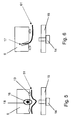
- Figure 5 is shown schematically how the flexible Printed circuit board 51 can be pressed by means of the pressure plate 15 on the spring contacts 13. With the rotatable on a shaft 16 eccentric 18 is the bulge of the flexible Printed circuit board 51 ausformbar.
- FIG. 6 shows schematically how the flexible printed circuit board 61 is inserted into a groove 17 can be to secure the end of the flexible circuit board 11.
- a groove 17 is present, the one Retracting the connecting plate 11 allowed within the device, so plugging in the groove 17. It is particularly advantageous that when changing a module only the flexible circuit board 61 of the module and its nearest neighbors from the respective groove 17 is to be taken out.
- the connecting plate can also from above between two Devices are inserted.
- connection units 1 and 2 so for NSV and the GSZ, can be arranged side by side and a common Cover is foreseeable.
- This cover is for the GSZ because of the occurring there Voltage levels required by law.
- this cover is now slightly extended executable and thus the connection unit 2 for the NSV also coverable. Since the cover for the GSZ certain insulating and shielding properties must meet, the NSV is also isolated and shielded accordingly. Thus, too Overall, the EMC immission and emission behavior of the converter system is very good.
Landscapes
- Engineering & Computer Science (AREA)
- Power Engineering (AREA)
- Inverter Devices (AREA)
- General Induction Heating (AREA)
- Control Of Motors That Do Not Use Commutators (AREA)
- Dc-Dc Converters (AREA)
Abstract
Description
In Figur 3 ist eine Vorderansicht skizziert.
In Figur 4 ist eine Draufsicht skizziert.
In Figur 4a ist eine Draufsicht skizziert auf zwei Anschlusseinheiten.
- 1
- Anschlusseinheit für NSV
- 2
- Anschlusseinheit für GSZ
- 3
- Motorversorgungsleitungen
- 5
- Ausnehmung
- 9
- Grundkörper
- 10
- Stromschienen
- 11
- Verbindungsplatte
- 12
- Zapfen
- 13
- Federkontakt
- 14
- Spannelemente
- 15
- Druckplatte
- 16
- Welle
- 17
- Nut
- 18
- Exzenter
- 51
- flexible Leiterplatte
- 61
- flexible Leiterplatte
Claims (11)
- Umrichtersystem, umfassend mindestens ein Versorgungsmodul VM und mindestens ein Achsmodul AM,
wobei die Module elektrische erste Anschlussvorrichtungen 13 für elektrischen Leitungen zum Herstellen von Niederspannungs- und Signalverbindungen aufweisen,
wobei die Module weitere Anschlussvorrichtungen für elektrische Leitungen 10 zur Leistungsversorgung der Achsmodule aufweisen,
wobei zum Herstellen der elektrischen Niederspannungs- und Signalverbindungen zwischen benachbarten Modulen jedes Modul eine verschiebbare Verbindungsplatte 11 umfasst, welche freiliegende Bereiche von elektrischen Leiterbahnen derart aufweist, dass bei geeigneter Verschiebung und/oder Positionierung der Verbindungsplatte 11 die ersten Anschlussvorrichtungen 13 mit den freiliegenden Bereichen in elektrischen Kontakt bringbar sind. - Umrichtersystem nach mindesten einem der vorangegangenen Ansprüche,
dadurch gekennzeichnet, dass
die ersten Anschlussvorrichtungen 13 mit den freiliegenden Bereichen mittels Spannelementen 14 und/oder einer Druckplatte 15 in elektrischen Kontakt bringbar sind. - Umrichtersystem nach mindesten einem der vorangegangenen Ansprüche,
dadurch gekennzeichnet, dass
der Gleichspannungszwischenkreis GSZ zur Leistungsversorgung der Module dient. - Umrichtersystem nach mindesten einem der vorangegangenen Ansprüche,
dadurch gekennzeichnet, dass
die Spannelemente 14 und/oder Druckplatte 15 zur elektrischen Isolierung und/oder Einhaltung elektrischer Vorschriften ausgelegt und verwendet sind. - Umrichtersystem nach mindesten einem der vorangegangenen Ansprüche,
dadurch gekennzeichnet, dass
der Grundkörper 9, die Druckplatte 15 und/oder die Spannelemente 14 aus Kunststoff, insbesondere aus Kunststoffspritzguss, ausgeführt sind. - Umrichtersystem nach mindesten einem der Ansprüche 1 bis 4,
dadurch gekennzeichnet, dass
der Grundkörper 9, die Druckplatte 15 und/oder die Spannelemente 14 zumindest teilweise metallisch ausgeführt sind. - Umrichtersystem nach mindesten einem der vorangegangenen Ansprüche,
dadurch gekennzeichnet, dass
die Druckplatte 15 eine metallische Schicht, eine flächige Schirmplatte oder eine metallische Folie umfasst. - Umrichtersystem nach mindesten einem der vorangegangenen Ansprüche,
dadurch gekennzeichnet, dass
die Module jeweils eine Abdeckung zur elektrischen Isolierung der weiteren Anschlussvorrichtungen für elektrischen Leitungen 10 für Starkstrom aufweisen
und dass die Abdeckung auch für die ersten Anschlussvorrichtungen 13 vorgesehen ist, insbesondere auch zur Isolierung und/oder Einhaltung elektrischer Vorschriften. - Umrichtersystem nach mindesten einem der vorangegangenen Ansprüche,
dadurch gekennzeichnet, dass
die Verbindungsplatte 11 an mindestens einer Position arretierbar oder befestigbar ist und nach Loslösen verschiebbar ist. - Umrichtersystem nach mindesten einem der vorangegangenen Ansprüche,
dadurch gekennzeichnet, dass
das Umrichtersystem verschieden breite Module umfasst
und dass die Breite der Verbindungsplatte 11 jeweils auf die Breite der Module derart abgestimmt ist, dass die Kontaktierung der Federkontakte 13 des Nachbarmoduls durch Verschieben um bei allen Modulen stets den selben Betrag erreichbar ist. - Umrichtersystem nach mindesten einem der vorangegangenen Ansprüche,
dadurch gekennzeichnet, dass
die Anschlusseinheiten 1,2 mittels einer gemeinsamen Abdeckung versehen sind.
Applications Claiming Priority (2)
| Application Number | Priority Date | Filing Date | Title |
|---|---|---|---|
| DE10235324 | 2002-08-01 | ||
| DE10235324 | 2002-08-01 |
Publications (2)
| Publication Number | Publication Date |
|---|---|
| EP1387443A1 true EP1387443A1 (de) | 2004-02-04 |
| EP1387443B1 EP1387443B1 (de) | 2009-08-12 |
Family
ID=30010560
Family Applications (1)
| Application Number | Title | Priority Date | Filing Date |
|---|---|---|---|
| EP03012889A Expired - Lifetime EP1387443B1 (de) | 2002-08-01 | 2003-06-06 | Umrichtersystem |
Country Status (4)
| Country | Link |
|---|---|
| EP (1) | EP1387443B1 (de) |
| AT (1) | ATE439690T1 (de) |
| DE (2) | DE50311798D1 (de) |
| DK (1) | DK1387443T3 (de) |
Cited By (1)
| Publication number | Priority date | Publication date | Assignee | Title |
|---|---|---|---|---|
| CN107851912A (zh) * | 2015-10-27 | 2018-03-27 | 索尤若驱动有限及两合公司 | 用于电气设备的接线单元、电气设备系统和制造方法 |
Families Citing this family (3)
| Publication number | Priority date | Publication date | Assignee | Title |
|---|---|---|---|---|
| DE102006052285A1 (de) * | 2006-11-03 | 2008-05-08 | Dr. Simon Consulting Gmbh | Hochspannungsnetzgerät |
| DE102010027901A1 (de) * | 2010-04-19 | 2011-10-20 | Beckhoff Automation Gmbh | Einspeisemodul |
| DE102010063978A1 (de) | 2010-12-22 | 2012-06-28 | Beckhoff Automation Gmbh | Verbindungsmodul und Verbindungssystem |
Citations (4)
| Publication number | Priority date | Publication date | Assignee | Title |
|---|---|---|---|---|
| US5259781A (en) * | 1992-11-18 | 1993-11-09 | International Business Machines Corporation | Electrical connector alignment and actuation assembly |
| DE19509658A1 (de) * | 1995-03-17 | 1996-09-26 | Lenze Gmbh & Co Kg Aerzen | Schaltungsanordnung zur Erzeugung eines Netzausfallsignals bei einem Antriebsregelgerät |
| US6336815B1 (en) * | 2000-10-11 | 2002-01-08 | Unisys Corporation | Connector for sending power to an IC-chip thru two pressed joints in series |
| US20020098742A1 (en) * | 2001-01-25 | 2002-07-25 | Harris Shaun L. | Power supply attachment mechanism and method |
Family Cites Families (4)
| Publication number | Priority date | Publication date | Assignee | Title |
|---|---|---|---|---|
| FR2608847B1 (fr) * | 1986-12-19 | 1989-04-21 | Legrand Sa | Connecteur de liaison pour appareil electrique a mise en place par encliquetage sur un rail de montage, et appareil electrique propre a la mise en oeuvre d'un tel connecteur de liaison |
| DE8804649U1 (de) * | 1988-04-08 | 1988-06-16 | Murrelektronik GmbH, 7155 Oppenweiler | Elektrisches Gerät, z.B. Schaltgerät, Einschaltverzögerer od. dgl. |
| US5493194A (en) * | 1995-02-14 | 1996-02-20 | Allen-Bradley Company, Inc. | Control signal and power bus connector arrangement for a multi-axis motor control |
| DE10230393B4 (de) * | 2002-07-05 | 2015-06-18 | Siemens Aktiengesellschaft | Frontseitige Abdeckung |
-
2003
- 2003-06-06 EP EP03012889A patent/EP1387443B1/de not_active Expired - Lifetime
- 2003-06-06 DE DE50311798T patent/DE50311798D1/de not_active Expired - Lifetime
- 2003-06-06 AT AT03012889T patent/ATE439690T1/de not_active IP Right Cessation
- 2003-06-06 DK DK03012889T patent/DK1387443T3/da active
- 2003-06-07 DE DE10325956.2A patent/DE10325956B4/de not_active Expired - Lifetime
Patent Citations (4)
| Publication number | Priority date | Publication date | Assignee | Title |
|---|---|---|---|---|
| US5259781A (en) * | 1992-11-18 | 1993-11-09 | International Business Machines Corporation | Electrical connector alignment and actuation assembly |
| DE19509658A1 (de) * | 1995-03-17 | 1996-09-26 | Lenze Gmbh & Co Kg Aerzen | Schaltungsanordnung zur Erzeugung eines Netzausfallsignals bei einem Antriebsregelgerät |
| US6336815B1 (en) * | 2000-10-11 | 2002-01-08 | Unisys Corporation | Connector for sending power to an IC-chip thru two pressed joints in series |
| US20020098742A1 (en) * | 2001-01-25 | 2002-07-25 | Harris Shaun L. | Power supply attachment mechanism and method |
Non-Patent Citations (1)
| Title |
|---|
| "Betriebsanleitung 09223703DE", SEW-EURODRIVE GMBH&CO, BRUCHSAL (DE), XP002261570 * |
Cited By (2)
| Publication number | Priority date | Publication date | Assignee | Title |
|---|---|---|---|---|
| CN107851912A (zh) * | 2015-10-27 | 2018-03-27 | 索尤若驱动有限及两合公司 | 用于电气设备的接线单元、电气设备系统和制造方法 |
| CN107851912B (zh) * | 2015-10-27 | 2020-11-17 | 索尤若驱动有限及两合公司 | 用于电气设备的接线单元、电气设备系统和制造方法 |
Also Published As
| Publication number | Publication date |
|---|---|
| DE10325956B4 (de) | 2015-01-08 |
| DK1387443T3 (da) | 2009-10-19 |
| DE10325956A1 (de) | 2004-03-04 |
| EP1387443B1 (de) | 2009-08-12 |
| DE50311798D1 (de) | 2009-09-24 |
| ATE439690T1 (de) | 2009-08-15 |
Similar Documents
| Publication | Publication Date | Title |
|---|---|---|
| DE60218961T2 (de) | Einpress-Sammelschiene für Leistungsversorgung | |
| DE102017205970A1 (de) | Lösbare elektrische Verbindung einer Leistungselektronik mit einer E-Maschine | |
| DE4437316C2 (de) | Dezentrale Ein/Ausgabebaugruppe für elektronische Steuerungen | |
| DE2105213A1 (de) | Elektrische Stromversorgungsvor richtung | |
| EP3631922A1 (de) | Stromverteiler | |
| DE102022207069A1 (de) | Schraubklemme für eine Kontaktbrücke, Kontaktbrücke sowie Fahrzeug | |
| EP2091113B1 (de) | Verbindungssystem für Lichtbänder oder Leuchten | |
| WO2007073880A1 (de) | Elektrisch betreibbare flächenheizelement-anordnung, insbesondere als fussboden-flächenheizelement-anordnung | |
| DE102018214104A1 (de) | Elektromaschine und Montageverfahren | |
| DE102017217418A1 (de) | Steuergerät, Antriebseinrichtung | |
| EP1387443B1 (de) | Umrichtersystem | |
| DE102012020219B4 (de) | Vorrichtung zum Kontaktieren von elektrischen Leitern und/oder elektrischen Kontaktelementen, sowie Leuchte oder elektrisches Gerät | |
| DE2251020B2 (de) | Anschlussvorrichtung | |
| EP1978600B1 (de) | Platinenanordnung | |
| DE102017127895A1 (de) | Wechselrichter für Elektromotor | |
| DE69411294T2 (de) | Anschlussblock für elektrisches Geräte und Leistungsumformer mit einem derartigen Anschlu block | |
| EP1523790A1 (de) | Steckverbindung mit zus tzlicher kontakteinrichtung, i nsbesondere zur daten bertragung | |
| DE102019200021B4 (de) | Kontaktierungsvorrichtung | |
| EP1291983B1 (de) | Anschlusseinheit für elektrische Module | |
| DE102009007956B4 (de) | Umrichter | |
| EP2037469A1 (de) | Leiterplattenrelais | |
| EP1162694B1 (de) | Vorrichtung zum Verbinden von elektrischen Leitern | |
| EP0175942A1 (de) | Rahmen zur Aufnahme von einschiebbaren elektrischen Baugruppen | |
| DE102015004464B4 (de) | Energiespeicheranordnung, insbesondere für ein Kraftfahrzeug | |
| DE3409762A1 (de) | Zusatzgeraet fuer einen elektrizitaetszaehler |
Legal Events
| Date | Code | Title | Description |
|---|---|---|---|
| PUAI | Public reference made under article 153(3) epc to a published international application that has entered the european phase |
Free format text: ORIGINAL CODE: 0009012 |
|
| AK | Designated contracting states |
Kind code of ref document: A1 Designated state(s): AT BE BG CH CY CZ DE DK EE ES FI FR GB GR HU IE IT LI LU MC NL PT RO SE SI SK TR |
|
| AX | Request for extension of the european patent |
Extension state: AL LT LV MK |
|
| 17P | Request for examination filed |
Effective date: 20040804 |
|
| AKX | Designation fees paid |
Designated state(s): AT BE BG CH CY CZ DE DK EE ES FI FR GB GR HU IE IT LI LU MC NL PT RO SE SI SK TR |
|
| GRAP | Despatch of communication of intention to grant a patent |
Free format text: ORIGINAL CODE: EPIDOSNIGR1 |
|
| GRAS | Grant fee paid |
Free format text: ORIGINAL CODE: EPIDOSNIGR3 |
|
| GRAA | (expected) grant |
Free format text: ORIGINAL CODE: 0009210 |
|
| AK | Designated contracting states |
Kind code of ref document: B1 Designated state(s): AT BE BG CH CY CZ DE DK EE ES FI FR GB GR HU IE IT LI LU MC NL PT RO SE SI SK TR |
|
| REG | Reference to a national code |
Ref country code: GB Ref legal event code: FG4D Free format text: NOT ENGLISH |
|
| REG | Reference to a national code |
Ref country code: CH Ref legal event code: EP |
|
| REG | Reference to a national code |
Ref country code: IE Ref legal event code: FG4D |
|
| REF | Corresponds to: |
Ref document number: 50311798 Country of ref document: DE Date of ref document: 20090924 Kind code of ref document: P |
|
| REG | Reference to a national code |
Ref country code: DK Ref legal event code: T3 |
|
| PG25 | Lapsed in a contracting state [announced via postgrant information from national office to epo] |
Ref country code: FI Free format text: LAPSE BECAUSE OF FAILURE TO SUBMIT A TRANSLATION OF THE DESCRIPTION OR TO PAY THE FEE WITHIN THE PRESCRIBED TIME-LIMIT Effective date: 20090812 Ref country code: ES Free format text: LAPSE BECAUSE OF FAILURE TO SUBMIT A TRANSLATION OF THE DESCRIPTION OR TO PAY THE FEE WITHIN THE PRESCRIBED TIME-LIMIT Effective date: 20091123 Ref country code: SE Free format text: LAPSE BECAUSE OF FAILURE TO SUBMIT A TRANSLATION OF THE DESCRIPTION OR TO PAY THE FEE WITHIN THE PRESCRIBED TIME-LIMIT Effective date: 20090812 |
|
| NLV1 | Nl: lapsed or annulled due to failure to fulfill the requirements of art. 29p and 29m of the patents act | ||
| PG25 | Lapsed in a contracting state [announced via postgrant information from national office to epo] |
Ref country code: SI Free format text: LAPSE BECAUSE OF FAILURE TO SUBMIT A TRANSLATION OF THE DESCRIPTION OR TO PAY THE FEE WITHIN THE PRESCRIBED TIME-LIMIT Effective date: 20090812 Ref country code: NL Free format text: LAPSE BECAUSE OF FAILURE TO SUBMIT A TRANSLATION OF THE DESCRIPTION OR TO PAY THE FEE WITHIN THE PRESCRIBED TIME-LIMIT Effective date: 20090812 |
|
| REG | Reference to a national code |
Ref country code: IE Ref legal event code: FD4D |
|
| PG25 | Lapsed in a contracting state [announced via postgrant information from national office to epo] |
Ref country code: PT Free format text: LAPSE BECAUSE OF FAILURE TO SUBMIT A TRANSLATION OF THE DESCRIPTION OR TO PAY THE FEE WITHIN THE PRESCRIBED TIME-LIMIT Effective date: 20091212 Ref country code: BG Free format text: LAPSE BECAUSE OF FAILURE TO SUBMIT A TRANSLATION OF THE DESCRIPTION OR TO PAY THE FEE WITHIN THE PRESCRIBED TIME-LIMIT Effective date: 20091112 |
|
| PG25 | Lapsed in a contracting state [announced via postgrant information from national office to epo] |
Ref country code: RO Free format text: LAPSE BECAUSE OF FAILURE TO SUBMIT A TRANSLATION OF THE DESCRIPTION OR TO PAY THE FEE WITHIN THE PRESCRIBED TIME-LIMIT Effective date: 20090812 Ref country code: IE Free format text: LAPSE BECAUSE OF FAILURE TO SUBMIT A TRANSLATION OF THE DESCRIPTION OR TO PAY THE FEE WITHIN THE PRESCRIBED TIME-LIMIT Effective date: 20090812 Ref country code: EE Free format text: LAPSE BECAUSE OF FAILURE TO SUBMIT A TRANSLATION OF THE DESCRIPTION OR TO PAY THE FEE WITHIN THE PRESCRIBED TIME-LIMIT Effective date: 20090812 Ref country code: CZ Free format text: LAPSE BECAUSE OF FAILURE TO SUBMIT A TRANSLATION OF THE DESCRIPTION OR TO PAY THE FEE WITHIN THE PRESCRIBED TIME-LIMIT Effective date: 20090812 |
|
| PG25 | Lapsed in a contracting state [announced via postgrant information from national office to epo] |
Ref country code: SK Free format text: LAPSE BECAUSE OF FAILURE TO SUBMIT A TRANSLATION OF THE DESCRIPTION OR TO PAY THE FEE WITHIN THE PRESCRIBED TIME-LIMIT Effective date: 20090812 |
|
| PLBE | No opposition filed within time limit |
Free format text: ORIGINAL CODE: 0009261 |
|
| STAA | Information on the status of an ep patent application or granted ep patent |
Free format text: STATUS: NO OPPOSITION FILED WITHIN TIME LIMIT |
|
| 26N | No opposition filed |
Effective date: 20100517 |
|
| PG25 | Lapsed in a contracting state [announced via postgrant information from national office to epo] |
Ref country code: GR Free format text: LAPSE BECAUSE OF FAILURE TO SUBMIT A TRANSLATION OF THE DESCRIPTION OR TO PAY THE FEE WITHIN THE PRESCRIBED TIME-LIMIT Effective date: 20091113 |
|
| BERE | Be: lapsed |
Owner name: SEW-EURODRIVE G.M.B.H. & CO. KG Effective date: 20100630 |
|
| PG25 | Lapsed in a contracting state [announced via postgrant information from national office to epo] |
Ref country code: MC Free format text: LAPSE BECAUSE OF NON-PAYMENT OF DUE FEES Effective date: 20100630 |
|
| REG | Reference to a national code |
Ref country code: CH Ref legal event code: PL |
|
| PG25 | Lapsed in a contracting state [announced via postgrant information from national office to epo] |
Ref country code: IT Free format text: LAPSE BECAUSE OF FAILURE TO SUBMIT A TRANSLATION OF THE DESCRIPTION OR TO PAY THE FEE WITHIN THE PRESCRIBED TIME-LIMIT Effective date: 20090812 |
|
| PG25 | Lapsed in a contracting state [announced via postgrant information from national office to epo] |
Ref country code: LI Free format text: LAPSE BECAUSE OF NON-PAYMENT OF DUE FEES Effective date: 20100630 Ref country code: CH Free format text: LAPSE BECAUSE OF NON-PAYMENT OF DUE FEES Effective date: 20100630 |
|
| PG25 | Lapsed in a contracting state [announced via postgrant information from national office to epo] |
Ref country code: BE Free format text: LAPSE BECAUSE OF NON-PAYMENT OF DUE FEES Effective date: 20100630 |
|
| PG25 | Lapsed in a contracting state [announced via postgrant information from national office to epo] |
Ref country code: AT Free format text: LAPSE BECAUSE OF NON-PAYMENT OF DUE FEES Effective date: 20100606 |
|
| PG25 | Lapsed in a contracting state [announced via postgrant information from national office to epo] |
Ref country code: CY Free format text: LAPSE BECAUSE OF FAILURE TO SUBMIT A TRANSLATION OF THE DESCRIPTION OR TO PAY THE FEE WITHIN THE PRESCRIBED TIME-LIMIT Effective date: 20090812 |
|
| PG25 | Lapsed in a contracting state [announced via postgrant information from national office to epo] |
Ref country code: HU Free format text: LAPSE BECAUSE OF FAILURE TO SUBMIT A TRANSLATION OF THE DESCRIPTION OR TO PAY THE FEE WITHIN THE PRESCRIBED TIME-LIMIT Effective date: 20100213 Ref country code: LU Free format text: LAPSE BECAUSE OF NON-PAYMENT OF DUE FEES Effective date: 20100606 |
|
| PG25 | Lapsed in a contracting state [announced via postgrant information from national office to epo] |
Ref country code: TR Free format text: LAPSE BECAUSE OF FAILURE TO SUBMIT A TRANSLATION OF THE DESCRIPTION OR TO PAY THE FEE WITHIN THE PRESCRIBED TIME-LIMIT Effective date: 20090812 |
|
| REG | Reference to a national code |
Ref country code: FR Ref legal event code: PLFP Year of fee payment: 14 |
|
| REG | Reference to a national code |
Ref country code: FR Ref legal event code: PLFP Year of fee payment: 15 |
|
| REG | Reference to a national code |
Ref country code: FR Ref legal event code: PLFP Year of fee payment: 16 |
|
| PGFP | Annual fee paid to national office [announced via postgrant information from national office to epo] |
Ref country code: GB Payment date: 20220506 Year of fee payment: 20 Ref country code: FR Payment date: 20220510 Year of fee payment: 20 Ref country code: DK Payment date: 20220610 Year of fee payment: 20 Ref country code: DE Payment date: 20220630 Year of fee payment: 20 |
|
| REG | Reference to a national code |
Ref country code: DE Ref legal event code: R071 Ref document number: 50311798 Country of ref document: DE |
|
| REG | Reference to a national code |
Ref country code: DK Ref legal event code: EUP Expiry date: 20230606 |
|
| REG | Reference to a national code |
Ref country code: GB Ref legal event code: PE20 Expiry date: 20230605 |
|
| PG25 | Lapsed in a contracting state [announced via postgrant information from national office to epo] |
Ref country code: GB Free format text: LAPSE BECAUSE OF EXPIRATION OF PROTECTION Effective date: 20230605 |