Technical Field
-
The present invention relates to zoom lenses and electronic still
cameras using the same. More specifically, it relates to high-picture
quality zoom lenses used in electronic still cameras, zoom lenses
provided with a camera shake-correction function, and electronic still
cameras using these zoom lenses.
Background Art
-
As personal computers have become more sophisticated and
widespread, electronic still cameras quickly have gained popularity as
image input devices. The total pixel number of the solid-state imaging
elements used in electronic still cameras has reached more than 1
million pixels, and recently, electronic still cameras provided with
solid-state imaging elements having a total pixel number greater than 3
million pixels also have appeared on the market. Video cameras that
are capable of shooting high-quality still images in addition to moving
pictures also have been released on the market.
-
Although electronic still cameras come in many forms, one
example is a compact type electronic still camera provided with a zoom
lens having a ×2 to ×3 zoom ratio. Compact electronic still cameras
must be easy to carry, and zoom lenses constituted by three groups have
been proposed as zoom lenses that meet this requirement (for example,
JP H11-52246A and JP H11-287953A). Zoom lenses constituted by
three groups are made of a first lens group having a negative power, a
second lens group having a positive power, and a third lens group having
a positive power, arranged in that order from the object side to the image
plane side. When zooming from the wide-angle end to the telescope end,
the air gap between the first lens group and the second lens group is
monotonically reduced and the air gap between the second lens group
and the third lens group is monotonically increased. The third lens
group is moved in the direction of the optical axis to carry out focus
adjustment. Here, the third lens group is suited for autofocus because
it is made of a single lens with a small outer diameter and can be driven
at high speeds using a compact motor. Movement of the first lens group
and the second lens group is carried out using cylindrical cams.
Consequently, a collapsing configuration in which all three lens groups
are drawn toward the solid-state imaging element using cylindrical cams
when the zoom lens is not in use can be adopted. Also, if such a zoom
lens is used in an electronic still camera, then the electronic still camera
can be made thin in the depth direction when not in use.
-
With solid-state imaging elements, when the pixel number is
increased but the picture size is kept the same, the pixel pitch becomes
smaller, lowering the aperture ratio and the photosensitivity.
Accordingly, by providing a miniature positive lens at each pixel of the
solid-state imaging element, the effective aperture ratio is increased,
preventing a drop in the photosensitivity. In this case, to let most of the
light emitted from the miniature positive lenses arrive at the
corresponding pixels, it is necessary to configure the zoom lens so that
the principal rays that are incident on the pixels are substantially
parallel to the optical axis. That is, there must be good telecentricity.
-
Solid-state imaging element performs spatial sampling due to
their pixel structure, however, an optical low-pass filter generally is
arranged between the zoom lens and the solid-state imaging element to
remove the aliasing distortion that occurs at this time, removing
high-frequency components from the image formed by the zoom lens.
Optical low-pass filters generally are made of a quartz plate. Here,
when natural light is incident on the quartz plate, the natural light is
split into an ordinary ray and an extraordinary ray due to the
birefringence of the quartz, and these are emitted parallel to one
another.
-
Among video cameras, video cameras provided with a camera
shake-correction function for correcting vibration in the captured image
when the user's hand shakes have been released on the market. Many
techniques have been proposed for camera shake correction, and a
method for parallel displacement of a portion of the lens groups of the
zoom lens in the direction perpendicular to the optical axis has been
adopted (for example, JP 2000-298235A).
-
JP H11-52245A discloses a zoom lens made of a first lens group
having a negative power, a second lens group having a positive power, a
third lens group having a positive power, and a fourth lens group having
a positive power or a negative power, arranged in that order from the
object side to the image plane side, wherein correction of camera shake is
carried out by parallel displacement of the third lens group in the
direction perpendicular to the optical axis. This publication also
discloses that decentered curvature of field and decentered coma
aberration when the third lens group is parallel displaced can be
corrected favorably.
-
Regarding the design of a zoom lens provided with a camera
shake-correction function, Kenichi KIMURA et. al. in "Aberration Theory
Applications in Anti-Vibration Optical Systems" (19th Optics Symposium
Proceedings, page 47 to 50, 1994) have proposed a method for using
decentered third-order aberration. Also, Yoshiya MATSUI in "Theory of
Decentered Optical System and Its Application" (Kogaku, Volume 24
Issue 12, page 708 to 712, December 1995) present a third-order
aberration theory of decentered optical system.
-
To provide the images captured by an electronic still camera with
high resolution, its zoom lens must have high resolution. However, the
astigmatism of the zoom lens disclosed in the aforementioned JP
H11-287953A is insufficient for correcting the curvature of field, and
thus there is the problem that the overall image cannot be made high
resolution.
-
To make an electronic still camera thin in the depth direction
when not in use, it is possible to adopt a configuration in which the zoom
lens collapses, however, to shorten the overall optical length (the
distance from the object side end of the zoom lens to the light-receiving
surface of the solid-state imaging element) when a three-group zoom lens
is collapsed, it is necessary to shorten the overall length of each of the
lens groups. However, with the zoom lens disclosed in the
aforementioned JP H11-52246A, since the second lens group includes a
long air gap or a lens with a thick center portion, there is the problem
that the overall length of the second lens group is long and even if a
collapsing configuration is adopted, the overall optical length when
collapsed is not very short. Also, a moving lens barrel that moves
during zooming and a stationary lens barrel that supports the moving
lens barrel are required for a collapsing configuration, however, if the
overall optical length during use is significantly longer than the overall
optical length when collapsed, then the stationary lens barrel cannot
stably support the moving lens barrel, and thus there is the problem that
a portion of the lens groups becomes decentered, leading to a drop in the
image-formation properties of the captured image.
-
The zoom lens disclosed in JP H11-52245A is made of ten or
eleven lenses, and since the number of lenses is large, there is the
problem of increased costs. Another problem with the zoom lens
disclosed in this publication is that it has poor telecentricity.
-
Because the number of pixels of solid-state imaging elements
used in electronic still cameras is much larger than the number of pixels
of solid-state imaging elements used in conventional video cameras,
when a video camera zoom lens provided with a camera shake-correction
function is used in an electronic still camera, the image-formation
properties at the peripheral portion of image in a state where camera
shake is corrected are poorer than the image-formation properties in a
state where camera shake has not been corrected (in the standard state).
-
If camera shake correction is performed by parallel displacement
of a portion of the lens groups in the direction perpendicular to the
optical axis, then to obtain good image-formation properties when
camera shake is corrected, it is conceivably possible to reduce as much as
possible the various aberrations in the lens groups that is parallel
displaced. To do this, however, a large number of lenses must be
combined, making the lens group that is parallel displaced heavy.
When the lens group that is parallel displaced is heavy, an actuator with
a large drive force and large external dimensions must be used to secure
the required response speed. However, when the actuator is large, it is
difficult to achieve an electronic still camera that is compact.
Disclosure of Invention
-
The present invention was arrived at in order to solve the
foregoing problems of the prior art, and it is an object thereof to provide
zoom lenses with a zoom ratio of ×2.5 to ×3.2 and an angle of view at the
wide-angle end of about 60°, and that have high resolution and a short
overall optical length when not in use, and moreover to provide zoom
lenses that include a camera shake correction function. It is a further
object of the present invention to use these zoom lenses to provide
electronic still cameras with high resolution and that are thin in the
depth direction when not being used, and furthermore to provide
electronic still cameras that include a camera shake correction function.
-
To achieve the foregoing objects, a zoom lens of a first
configuration according to the present invention is provided with a first
lens group with a negative power, an aperture stop, a second lens group
with a positive power, and a third lens group with a positive power,
arranged in that order from an object side to an image plane side,
wherein the first lens group includes a first lens that is a negative
meniscus lens whose surface with strong curvature is facing the image
plane, a second lens that is a negative meniscus lens whose surface with
strong curvature is facing the image plane, and a third lens that is a
positive lens, arranged in that order from the object side, the second lens
group includes a fourth lens that is a positive lens, a fifth lens that is a
positive lens, a sixth lens that is a negative lens, and a seventh lens that
is a positive lens, arranged in that order from the object side, the third
lens group includes a single positive lens and can be moved in the optical
axis direction for focus adjustment, the image plane-side surface of the
first lens or the second lens is an aspherical surface whose local radius of
curvature is monotonically increased as distance from the center
increases, the object-side surface of the fourth lens is an aspherical
surface whose local radius of curvature is monotonically increased as
distance from the center increases, the object-side surface of the seventh
lens is an aspherical surface whose local radius of curvature is
monotonically increased as distance from the center increases, or the
image plane-side surface of the seventh lens is an aspherical surface
whose local radius of curvature is monotonically decreased as distance
from the center increases, wherein when zooming from a wide-angle end
to a telescope end, an air gap between the first lens group and the second
lens group is reduced and an air gap from the second lens group to the
third lens group is increased, and a zoom ratio is ×2.5 to ×3.2 if the
shooting distance is ∞.
-
In the zoom lens of the first configuration according to the
present invention, when the shooting distance is ∞, fW is a combined
focal length of the overall lens system at the wide-angle end, fG2 is a
combined focal length of the second lens group, fG3 is a combined focal
length of the third lens group, and dL6 is an air gap between the sixth
lens and the seventh lens, it is preferable that then the conditional
expressions
2.0 < fG2 / fW < 3.0
4.0 < fG3 / fW < 7.0
0.02 < dL6 / fG2 < 0.1
are satisfied.
-
In this case, when f4 is a focal length of the fourth lens and f7 is a
focal length of the seventh lens, then it is preferable that the conditional
expressions
0.8 < f4 / fG2 < 1.2
1.6 < f7 / fG2 < 3.0
are satisfied.
-
In the zoom lens of the first configuration according to the
present invention, it is preferable that the fifth lens and the sixth lens
are cemented.
-
In the zoom lens of the first configuration according to the
present invention, it is preferable that the sixth lens and the seventh
lens are in contact outside their effective diameters.
-
In the zoom lens of the first configuration according to the
present invention, it is preferable that the third lens group is a cemented
lens constituted by a positive lens and a negative lens.
-
In the zoom lens of the first configuration according to the
present invention, it is preferable that the surface of the fourth lens that
is on the image plane side is a flat surface.
-
A zoom lens of a second configuration according to the present
invention is provided with a first lens group with a negative power, an
aperture stop, a second lens group with a positive power, and a third lens
group with a positive power, arranged in that order from an object side to
an image plane side, wherein when zooming from a wide-angle end to a
telescope end, an air gap between the first lens group and the second
lens group is reduced and an air gap between the second lens group and
the third lens group is increased, the third lens group can be moved in
the optical axis direction for focus adjustment, the second lens group can
be parallel displaced in the direction perpendicular to the optical axis, a
zoom ratio is ×2.5 to ×3.2 if the shooting distance is ∞, and when mG2T is
the magnification of the second lens group at the telescope end with a
shooting distance of ∞ and mG3T is the magnification of the third lens
group at the telescope end with a shooting distance of ∞, and σ is defined
as σ = (1 - mG2T)mG3T, then the conditional expression
1.7 < |σ| < 2.1
is satisfied.
-
In the zoom lens of the second configuration according to the
present invention, it is preferable that the first lens group includes a
first lens that is a negative meniscus lens whose surface with strong
curvature is facing the image plane, a second lens that is a negative
meniscus lens whose surface with strong curvature is facing the image
plane, and a third lens that is a positive lens, arranged in that order
from the object side, that the second lens group includes a fourth lens
that is a positive lens, a fifth lens that is a positive lens, a sixth lens that
is a negative lens, and a seventh lens that is a positive lens, arranged in
that order from the object side, that the third lens group includes a
single positive lens, that the image plane-side surface of the first lens or
the second lens is an aspherical surface whose local radius of curvature
is monotonically increased as distance from the center increases, that
the object-side surface of the fourth lens is an aspherical surface whose
local radius of curvature is monotonically increased as distance from the
center increases, that the object-side surface of the seventh lens is an
aspherical surface whose local radius of curvature is monotonically
increased as distance from the center increases, or the image plane-side
surface of the seventh lens is an aspherical surface whose local radius of
curvature is monotonically decreased as distance from the center
increases, that an air gap between the aperture stop and the second lens
group is constant, and that the position of the aperture stop in the
direction perpendicular to the optical axis is fixed.
-
In this case, it is preferable that the fifth lens and the sixth lens
are cemented.
-
In this case, it is also preferable that the sixth lens and the
seventh lens are in contact outside their effective diameters.
-
In this case, it is moreover preferable that the third lens group is
a cemented lens constituted by a positive lens and a negative lens.
-
In this case, it is also preferable that the surface of the fourth
lens that is on the image plane side is a flat surface.
-
In the zoom lens of the second configuration according to the
present invention, when the shooting distance is ∞, fW is a combined
focal length of the overall lens system at the wide-angle end, fG2 is a
combined focal length of the second lens group, fG3 is a combined focal
length of the third lens group, and dL6 is an air gap between the sixth
lens and the seventh lens, then it is preferable that the conditional
expressions
2.2 < fG2 / fW < 2.8
4.0 < fG3 / fW < 7.0
0.02 < dL6 / fG2 < 0.1
are satisfied.
-
In this case, when f4 is a focal length of the fourth lens and f7 is a
focal length of the seventh lens, then it is preferable that the conditional
expressions
0.8 < f4 / fG2 < 1.2
1.5 < f7 / fG2 < 3.0
are satisfied.
-
In the zoom lens of the second configuration according to the
present invention, when n7 is the refractive index of the seventh lens, r7F
is the paraxial radius of curvature of its surface on the object side, κ7F is
the conic constant of its surface on the object side, D7F is the fourth-order
aspheric coefficient of its surface on the object side, r7R is the paraxial
radius of curvature of its surface on the image plane side, κ7R is the conic
constant of its surface on the image plane side, D7R is the fourth-order
aspheric coefficient of its surface on the image plane side, and fT is the
combined focal length of the overall lens system at the telescope end
when the shooting distance is ∞, then it is preferable that B7 in
Expression 1 satisfies the below condition.
-5 < B7 < -15
Expression 1 B7 = (n7 -1)(κ7F r7F 3 + 8D7F - κ7R r7R 3 - 8D7R)fT 3
-
An electronic still camera of a first configuration according to the
present invention includes a zoom lens and a solid-state imaging element,
wherein the zoom lens that is used is the zoom lens of the first
configuration according to the present invention.
-
In the electronic still camera of the first configuration according
to the present invention, it is preferable that a miniature positive lens is
provided at each pixel of the solid-state imaging element.
-
An electronic still camera of a second configuration according to
the present invention is provided with a zoom lens in which a portion of
the lens groups are parallel displaced in a direction perpendicular to an
optical axis, a solid-state imaging element, a camera shake detection
means for detecting a camera shake angle in two directions, and a lens
group drive means for parallel displacing the parallel displaced lens
group in correspondence with signals output by the camera shake
detection means, wherein the zoom lens that is used is the zoom lens of
the second configuration according to the present invention.
-
In the electronic still camera of the second configuration
according to the present invention, it is preferable that a miniature
positive lens is provided at each pixel of the solid-state imaging element.
-
The electronic still camera of the second configuration according
to the present invention is preferably provided with an electronic zoom
means that uses a signal processing circuit to magnify, up to the entire
picture, an image formed in a center portion of the solid-state imaging
element.
-
Hereinafter, the operations of the zoom lenses of the first
configuration and the second configuration of the present invention are
described.
-
A lens system made of a first lens group having a negative power
and a second lens group having a positive power is configured so that the
focal length of the overall lens system is changed by altering the air gap
between the two lens groups. Also, by shifting the third lens group
having a positive power in the direction of the optical axis, focus
adjustment is performed. The third lens group has good telecentricity,
and thus a drop in photosensitivity at portions around the picture at the
wide-angle end in a case where a solid-state imaging element provided
with miniature positive lenses for each pixel is used can be prevented.
Also, the third lens group is small and lightweight, and can be driven at
high speeds using a compact motor, thus allowing autofocus adjustment
to be performed at high speeds.
-
By constituting the first lens group by three lenses, a negative
lens (first lens), a negative lens (second lens), and a positive lens (third
lens) and making the image plane-side surface of one of the two negative
lenses an aspherical surface, it is possible to suppress negative distortion.
Also, by generating positive distortion at the positive lens, it is possible
to reduce negative distortion at the wide-angle end of the overall lens
system. Moreover, because the image plane-side surface of either the
first lens or the second lens is an aspherical surface whose local radius of
curvature monotonically increases with increased distance from the
center, negative distortion that occurs at the first lens or the second lens
can be reduced. Furthermore, with respect to the seventh lens of the
second lens group that is disposed furthest on the image plane side,
either its surface on the object side is an aspherical surface whose local
radius of curvature increases monotonically with increased distance from
the center or its surface on the image plane side is an aspherical surface
whose local radius of curvature decreases monotonically with increased
distance from the center, so that there is less negative distortion
generated at the seventh lens than if both of its surfaces were spherical.
Through these three operations, a reduction in negative distortion at the
wide-angle end of the overall lens system is achieved.
-
The local radius of curvature ρ at the height h of the aspherical
surface from the optical axis is found as shown in Expression 2
Expression 2 ρ = 1+(dzdh )2 3/2 d2zdh2
-
In Expression 2 above, z denotes the sag amount at a height h on
the aspherical surface from the optical axis.
-
The local curvature is defined as 1 / ρ.
-
The second lens group is made of four lenses, and a positive lens
with a strong positive power is disposed furthest on the object side and a
positive lens with a weak positive power is disposed furthest on the
image plane side, so that the principal point of the second lens group on
the object side is deviated toward the object side. Consequently, at the
telescope end where the first lens group and the second lens group are
nearest one another, the distance between the principal point on the
image plane side of the first lens group and the principal point on the
object side of the second lens group can be shortened. As a result, it is
possible to reduce the combined focal length of the second lens group,
allowing the overall optical length when in use to be shortened.
-
Making at least one of the surfaces of the seventh lens an
aspherical surface reduces distortion, and this creates space that allows
the air gap between the sixth lens and the seventh lens to be reduced.
Also, by cementing the fifth lens and the sixth lens to one another, the
overall length of the second lens group can be reduced. Furthermore, by
constituting the third lens group by a single lens or a cemented lens
made of two lenses, the overall length of the third lens group can be
shortened. As a result, the overall optical length of the zoom lens of the
present invention when collapsed is shortened.
-
Because an aperture stop is arranged near the object side of the
second lens group, the incidence height of the axial ray is largest at the
fourth lens. Consequently, making the object-side surface of the fourth
lens an aspherical surface in which the local radius of curvature
increases monotonically with increased distance from the center allows
the overall spherical aberration of the lens system to be reduced.
-
The decenter tolerances of the four lenses making up the second
lens group are apt to become severe. By cementing the fifth lens and
the sixth lens and making the sixth lens and the seventh lens contact
one another outside their effective diameters, there is less decenter
during assembly. Also, making the image plane-side surface of the
fourth lens a flat surface allows the position of the fourth lens to be
easily adjusted in the direction perpendicular to the optical axis by
attaching the fourth lens after the fifth lens, the sixth lens, and the
seventh lens are incorporated into a lens barrel supporting the four
lenses of the second lens group, and thus makes it possible to further
reduce the decenter of the lenses in the second lens group.
-
In the zoom lens of the present invention, if the camera is shaken
while a picture is being captured, the second lens group can be parallel
displaced by an appropriate amount in the direction perpendicular to the
optical axis so as to keep the subject that is formed on the solid-state
imaging element from moving, without much deterioration of the image
forming properties during camera shake correction. Here, a parallel
displacement amount of zero of the second lens group is referred to as
the "standard state" and the state in which the second lens group has
been parallel displaced is the "state where camera shake has been
corrected."
-
The inventors of the present invention independently evaluated
decentered third-order aberration, and after performing various tests,
found that a method for parallel displacing the second lens group
perpendicularly to the optical axis is useful for correcting camera shake
in a zoom lens constituted by three lens groups.
-
When the magnification of the second lens group (parallel
displaced lens group) is regarded as mG2 and the magnification of the
third lens group is regarded as mG3, then the amount of image decenter
eM when the second lens group is parallel displaced by the amount eG2
perpendicularly to the optical axis is expressed by:
eM = (1 - mG2)mG3eG2
-
To prevent the image-formation properties from becoming worse
during correction of camera shake, it is necessary that the change in
aberration between the standard state and the state where camera shake
has been corrected is kept small. The inventors of the present invention
realized that, although a light beam with a small angle of view that
passes through the center portion of the aperture stop can be
approximated by third-order aberration, there is an increase in
approximation error when a light beam that passes through the
peripheral portion of the aperture stop is approximated by third-order
aberration, and reached the conclusion that to achieve good
image-formation properties during camera shake correction, the light
beam that passes through the center portion of the aperture stop and the
light beam that passes through the peripheral portion the aperture stop
should be considered separate. Also, in the present invention, the
amount of parallel displacement of the second lens group (parallel
displaced lens group) with respect to the light beam that passes through
peripheral portion of the aperture stop is kept small and the decentered
third-order aberration that occurs at the second lens group (parallel
displaced lens group) with respect to the light beam that passes through
the center portion of the aperture stop is kept small, so as to keep the
image-formation properties from deteriorating when camera shake is
corrected.
-
It is clear from Expression 21 that (1 - mG2)mG3 can be increased
to keep the amount of parallel displacement of the second lens group
(parallel displaced lens group) small. However, when (1 - mG2)mG3 is
made too large it becomes difficult to securely align the image to a
constant position during camera shake correction. Accordingly, in the
present invention, the amount by which the second lens group (parallel
displaced lens group) is parallel displaced is appropriately selected.
-
The inventor of the present invention, as the result of
individually evaluating the decentered third-order aberration of the
second lens group (parallel displaced lens group), has made the
image-formation properties during the standard state good and reduced
the decentered third-order aberration that occurs at the second lens
group (parallel displaced lens group) with respect to the light beam that
passes through the center portion of the aperture stop in the state where
camera shake has been corrected. The surfaces of the second lens group
(parallel displaced lens group) in which the decentered coma and the
decentered astigmatism are large are the object side surface of the fourth
lens, the image plane side surface of the sixth lens, and the aspherical
surface of the seventh lens. Of these three surfaces, the object side
surface of the fourth lens and the image plane side surface of the sixth
lens govern the power distribution and are governed by the
image-formation properties in the standard state, and therefore the
parameters cannot be significantly changed. However, since both
surfaces of the seventh lens have a low incidence height with respect to
axial ray, the parameters of the aspherical surface of the seventh lens
can be altered to a certain extent in order to achieve good
image-formation properties during camera shake correction.
Accordingly, in the present invention, conditions are provided with
regard to the surface of the seventh lens that is aspherical so that the
decentered coma and the decentered astigmatism of the second lens
group (parallel displaced lens group) are small.
-
The Conditional Expressions mentioned above are described
below.
-
Conditional Expression (1) is a condition for suppressing the
simultaneous occurrence of various aberrations when the overall optical
length is made extremely short. When fG2 / fW is above the upper limit,
the overall optical length during use becomes long because the distance
between the object and the image (distance from the object point to the
image point) of the second lens group becomes long. In this case,
although the overall optical length becomes short if the magnification of
the third lens group is reduced, since the power of the third lens group is
strong there is insufficient correction of the curvature of field that occurs
at the third lens group, and it becomes difficult to correct this curvature
of field at the first lens group and the second lens group. On the other
hand, when fG2 / fW is below the lower limit there is the benefit that the
overall optical length can be shortened, however, changes in the
spherical aberration that occurs at the second lens group due to the zoom
position become large, and it become difficult to correct the various
aberrations in a balanced manner from the wide-angle end to the
telescope end.
-
Conditional Expression (2) is a condition for reducing the slope
angle of the principal ray at the maximum image height at which it is
incident on the solid-state imaging element, that is, for improving the
telecentricity, and for reducing the curvature of field. When fG3 / fW is
below the lower limit, the telecentricity is good but the ability to correct
the curvature of field of the overall lens system is lost. On the other
hand, when fG3 / fW is above the upper limit, the curvature of field is
reduced but the telecentricity is insufficient.
-
Conditional Expression (3) is a condition for correcting the
various aberrations that occur at the second lens group in a balanced
manner and for shortening the overall length of the second lens group.
When dL6 / fG2 is above the upper limit, the overall length of the second
lens group becomes long. On the other hand, when dL6 / fG2 is below the
lower limit, the sixth lens and the seventh lens are in contact at
peripheral portions, and thus it is no longer possible to strengthen the
curvature of the image-plane side surface of the sixth lens or to reduce
the curvature of the object-side surface of the seventh lens, and it is
difficult to correct negative distortion at the wide-angle end. Also, the
ability to correct coma and astigmatism is lost.
-
Conditional Expressions (4) and (5) are conditions for correcting
the various aberrations that occur at the second lens group in a balanced
manner and for shortening the overall optical length of the overall lens
system when in use. When f4 / fG2 is above the upper limit or when f7 /
fG2 is below the lower limit, the principal point on the object side of the
second lens group is insufficiently deviated toward the object side, so
that the minimum distance between the principal point on the image
plane side of the first lens group and the principal point on the object
side of the second lens group is no longer short and the combined focal
length of the second lens group becomes long, and therefore it becomes
difficult to shorten the overall optical length of the overall lens system
when in use. Even if the overall optical length when collapsed can be
made short, if the overall optical length of the overall lens system during
use is long, then the first lens group and the second lens group cannot be
securely supported during use, and thus it is difficult to achieve good
image-formation properties during use. On the other hand, when f4 / fG2
is below the lower limit or when f7 / fG2 is above the upper limit, the
overall optical length of the overall lens system during use can be
reduced because the principal point on the object side of the second lens
group is sufficiently deviated to the object side, however, since the power
of the fourth lens becomes too strong, it becomes difficult to correct the
spherical aberration and the coma that occur at the fourth lens in a
balanced manner with the other lenses.
-
Conditional Expression (6) is a condition for achieving good
image-formation properties during correction of camera shake. When
|σ| = |(1 - mG2T)mG3T| is below the lower limit, the amount of decenter
of the second lens group (parallel displaced lens group) that is required
to make the image decenter by a predetermined amount becomes too
large, and thus the change in aberration due to parallel displacement of
the second lens group (parallel displaced lens group) becomes large,
resulting in worse image-formation properties at the margin of the image.
On the other hand, when |σ| = |(1 - mG2T)mG3T| is above the upper
limit, the amount of decenter of the second lens group (parallel displaced
lens group) that is required to make the image decenter by a
predetermined amount becomes too small, and it is difficult to parallel
displace the second lens group (parallel displaced lens group) with
precision. As a result, it is not possible to sufficiently reduce pixel
displacement while a picture is being captured, and thus it becomes
difficult to achieve good image-formation properties during correction of
camera shake.
-
Conditional Expressions (7) to (11) are the same as Conditional
Expressions (1) to (5) described above. It should be noted that in
Conditional Expression (1) and Conditional Expression (7) the lower
limit and the upper limit values are different, and in Conditional
Expression (5) and Conditional Expression (11) the lower limit values are
different. This is because leeway is required in the image-formation
properties in the standard state in order to achieve good image-formation
properties during correction of camera shake, and thus the value range
in Conditional Expression (7) is narrower than the value range in
Conditional Expression (1).
-
The Conditional Expression (12) is a condition for reducing
deterioration of the image-formation properties during correction of
camera shake by restricting the conic constant and the fourth-order
aspheric coefficient at the aspherical surface of the seventh lens with
respect to the light beam with a small angle of view that passes through
the center portion of the aperture stop. B7 defined in Expression 1 is
the amount that the aspherical surface of the seventh lens contributes to
the third-order aberration in a lens system normalized so that the
combined focal length at the telescope end of the entire lens system is 1.
The expression in the second parenthesis on the right side of Expression
1 is of a case where both surfaces are aspherical surfaces, and if only one
surface is aspherical, then there are only the two terms on the front side
or the two terms on the latter side (for third-order aberration of a lens
system in which decenter is not included, see "Lens Design Methods" by
Yoshiya MATSUI (Kyoritsu Shuppan, first edition, eighth printing,
September 20, 1991), pages 86 and 87).
-
Since the incidence height of axial ray is low with the seventh
lens, there is little change in the spherical aberration in the standard
state even if the conic constant and the fourth-order aspheric coefficient
of the seventh lens are changed, however, astigmatism in the standard
state and coma and astigmatism if the second lens group (parallel
displaced lens group) is parallel displaced are significantly changed.
Accordingly, by making one of the surfaces of the seventh lens an
aspherical surface and suitably selecting its conic constant and its
fourth-order aspheric coefficient, the decentered coma and the
decentered astigmatism of the second lens group as a whole in the state
where camera shake has been corrected can be reduced with little
deterioration of the image-formation properties in the standard state.
-
When B7 is above the upper limit or below the lower limit in
Conditional Expression (12), there is either too much or too little
decentered coma and decentered astigmatism caused by the aspherical
surface of the seventh lens, there is too much decentered coma and
decentered astigmatism in the second lens group as a whole in the state
where camera shake has been corrected, and it is no longer possible to
correct deterioration in the image-formation properties in the state
where camera shake is corrected.
-
A zoom lens of a third configuration according to the present
invention is provided with a first lens group with a negative power, an
aperture stop, a second lens group with a positive power, and a third lens
group with a positive power, arranged in that order from an object side to
an image plane side, wherein the first lens group includes a first lens
that is a negative meniscus lens whose surface with strong curvature is
facing the image plane, a second lens that is a negative meniscus lens
whose surface with strong curvature is facing the image plane, and a
third lens that is a positive lens, arranged in that order from the object
side, the second lens group includes a fourth lens that is a positive lens,
a fifth lens that is a positive lens, a sixth lens that is a negative lens,
and a seventh lens that is a biconvex lens, arranged in that order from
the object side, the third lens group includes a single positive lens and
can be moved in the optical axis direction for focus adjustment, the
image plane-side surface of the first lens or the second lens is an
aspherical surface, the object-side surface of the fourth lens is an
aspherical surface whose local radius of curvature is monotonically
increased as distance from the center increases, the object-side surface or
the image plane-side surface of the seventh lens is an aspherical surface
where an absolute value of the local radius of curvature has a local
maximum in a range from the center to the effective diameter, when
zooming from a wide-angle end to a telescope end, an air gap between
the first lens group and the second lens group is reduced and an air gap
between the second lens group and the third lens group is increased, and
if the shooting distance is ∞ a zoom ratio is ×2.5 to ×3.2.
-
In the zoom lens of the third configuration according to the
present invention, when the shooting distance is ∞, fw is a combined
focal length of the overall lens system at the wide-angle end, fG2 is a
combined focal length of the second lens group, fG3 is a combined focal
length of the third lens group, and dL6 is an air gap between the sixth
lens and the seventh lens, it is preferable that the conditional
expressions
2.2 < fG2 / fw < 2.8
4.0 < fG3 / fw < 7.0
0.05 < dL6 / fG2 < 0.15
are satisfied.
-
In this case, when f4 is a focal length of the fourth lens and f7 is a
focal length of the seventh lens, then it is preferable that the conditional
expressions
0.9 < f4 / fG2 < 1.2
1.2 < f7 / fG2 < 1.7
are satisfied.
-
In the zoom lens of the third configuration according to the
present invention, it is preferable that the fifth lens and the sixth lens
are cemented.
-
In the zoom lens of the third configuration according to the
present invention, it is preferable that the image-plane side surface of
the fourth lens is a flat surface.
-
In the zoom lens of the third configuration according to the
present invention, if the image-plane side surface of the first lens is an
aspherical surface, then it is preferable that the aspherical surface is an
aspherical surface in which the local radius of curvature is monotonically
increased as distance from the center increases.
-
In the zoom lens of the third configuration according to the
present invention, if the image-plane side surface of the second lens is an
aspherical surface, then it is preferable that the aspherical surface is an
aspherical surface in which the local curvature is monotonically
decreased as distance from the center increases and that the local
curvature at the effective diameter is negative.
-
In the zoom lens of the third configuration according to the
present invention, it is preferable that the third lens group is a cemented
lens constituted by a positive lens and a negative lens.
-
A zoom lens of a fourth configuration according to the present
invention is provided with a first lens group with a negative power, an
aperture stop, a second lens group with a positive power, and a third lens
group with a positive power, arranged in that order from an object side to
an image plane side, wherein the lens of the second lens group furthest
to the image-plane side can be parallel displaced in the direction
perpendicular to an optical axis, the third lens group can be moved in the
direction of the optical axis for focus adjustment, when zooming from a
wide-angle end to a telescope end an air gap between the first lens group
and the second lens group is reduced and an air gap between the second
lens group and the third lens group is increased, a zoom ratio is ×2.5 to
×3.2 if the shooting distance is ∞, and when mDT is the magnification of
the parallel displaced lens at the telescope end with a shooting distance
of ∞ and mG3T is the magnification of the third lens group at the
telescope end with a shooting distance of ∞, then the conditional
expression
0.9 < (1 - mDT)mG3T < 1.3
is satisfied.
-
In the zoom lens of the fourth configuration according to the
present invention, it is preferable that the first lens group includes a
first lens that is a negative meniscus lens whose surface with strong
curvature is facing the image plane, a second lens that is a negative
meniscus lens whose surface with strong curvature is facing the image
plane, and a third lens that is a positive lens, arranged in that order
from the object side, that the second lens group includes a fourth lens
that is a positive lens, a fifth lens that is a positive lens, a sixth lens that
is a negative lens, and a seventh lens that is a biconvex lens, arranged in
that order from the object side, that the third lens group includes a
single positive lens, that the image plane-side surface of the first lens or
the second lens is an aspherical surface, that the object-side surface of
the fourth lens is an aspherical surface whose local radius of curvature is
monotonically increased as distance from the center increases, that the
object-side surface or the image plane-side surface of the seventh lens is
an aspherical surface where an absolute value of the local radius of
curvature has a local maximum in a range from the center to the
effective diameter, that an air gap between the aperture stop and the
second lens group is constant, and that the position of the aperture stop
in the direction perpendicular to the optical axis is fixed.
-
In this case, if the image-plane side surface of the first lens is an
aspherical surface, then it is preferable that the aspherical surface is an
aspherical surface in which the local radius of curvature is monotonically
increased as distance from the center increases.
-
Also, in this case, if the image-plane side surface of the second
lens is an aspherical surface, then it is preferable that the aspherical
surface is an aspherical surface in which the local curvature is
monotonically decreased as distance from the center increases and that
the local curvature at the effective diameter is negative.
-
In the zoom lens of the fourth configuration according to the
present invention, when the shooting distance is ∞, fW is a combined
focal length of the overall lens system at the wide-angle end, fG2 is a
combined focal length of the second lens group, fG3 is a combined focal
length of the third lens group, and dL6 is an air gap between the sixth
lens and the seventh lens, then it is preferable that the conditional
expressions
2.2 < fG2 / fW < 2.8
4.0 < fG3 / fW < 7.0
0.05 < dL6 / fG2 < 0.15
are satisfied.
-
In this case, when f4 is a focal length of the fourth lens and f7 is a
focal length of the seventh lens, then it is preferable that the conditional
expressions
0.9 < f4 / fG2 < 1.2
1.2 < f7 / fG2 < 1.7
are satisfied.
-
In the zoom lens of the fourth configuration according to the
present invention, when n7 is the refractive index of the seventh lens, r7F
is the paraxial radius of curvature of its surface on the object side, κ7F is
the conic constant of its surface on the object side, D7F is the fourth-order
aspheric coefficient of its surface on the object side, r7R is the paraxial
radius of curvature of its surface on the image plane side, κ7R is the conic
constant of its surface on the image plane side, D7R is the fourth-order
aspheric coefficient of its surface on the image plane side, and fT is the
combined focal length of the overall lens system at the telescope end
when the shooting distance is ∞, then it is preferable that B7 defined by
Expression 3 below satisfies the conditions:
-0.7 < B7 < -1.5
Expression 3 B7 = (n7 -1)(κ7f r7F 3 + 8D7F - κ7R r7R 3 - 8D7R)fT 3
-
In the zoom lens of the fourth configuration according to the
present invention, when the Abbe number of the seventh lens at a d-line
is ν7, then it is preferable that the conditional expression
ν7 > 50
is satisfied.
-
In the zoom lens of the fourth configuration according to the
present invention, it is preferable that the fifth lens and the sixth lens
are cemented.
-
In the zoom lens of the fourth configuration according to the
present invention, it is preferable that the third lens group is a cemented
lens constituted by a positive lens and a negative lens.
-
In the zoom lens of the fourth configuration according to the
present invention, it is preferable that the image-plane side surface of
the fourth lens is a flat surface.
-
An electronic still camera of a third configuration according to
the present invention includes a zoom lens and a solid-state imaging
element, wherein the zoom lens that is used is the zoom lens of the third
configuration according to the present invention.
-
In the electronic still camera of the third configuration according
to the present invention, it is preferable that a miniature positive lens is
provided at each pixel of the solid-state imaging element.
-
An electronic still camera of a fourth configuration according to
the present invention is provided with a zoom lens in which a portion of
the lenses is parallel displaced in the direction perpendicular to the
optical axis, a solid-state imaging element, a camera shake detection
means for detecting a camera shake angle in two directions, and a lens
drive means for parallel displacing the parallel displaced lens in
correspondence with signals output by the camera shake detection
means, wherein the zoom lens that is used is the zoom lens of the fourth
configuration according to the present invention.
-
In the electronic still camera of the fourth configuration
according to the present invention, it is preferable that a miniature
positive lens is provided at each pixel of the solid-state imaging element.
-
The electronic still camera of the fourth configuration according
to the present invention is preferably provided with an electronic zoom
means that uses a signal processing circuit to magnify, up to the entire
picture, an image formed in a center portion of the solid-state imaging
element.
-
Hereinafter, the operations of the zoom lenses of the third
configuration and the fourth configuration of the present invention are
described, with emphasis placed on how they differ from the zoom lenses
of the first and the second configurations.
-
In the third and fourth configurations as well, by constituting the
first lens group by three lenses, a negative lens (first lens), a negative
lens (second lens), and a positive lens (third lens) and making the image
plane-side surface of one of the two negative lenses an aspherical surface,
it is possible to suppress negative distortion. Also, by generating
positive distortion at the positive lens, it is possible to reduce negative
distortion at the wide-angle lens of the overall lens system.
-
If the image plane side surface of the first lens is an aspherical
surface, then it is an aspherical surface in which the local radius of
curvature is increased monotonically as distance from the center
increases, and if the image plane side surface of the second lens is an
aspherical surface, then it is an aspherical surface in which the local
curvature is monotonically decreased as distance from the center
increases and in which the local curvature at its effective diameter is
negative. If both surfaces of the first and second lens, which are both
negative lenses, are spherical, for a total of four spherical surfaces, then
the refractive power becomes too strong as the point of incidence
becomes farther from the center, thus causing a large negative distortion
at the wide-angle end, however, by making the image plane-side surface
of either one of the lenses an aspheric surface as described above, the
refractive power can be kept from becoming extremely strong even if the
point of incidence is distant from the center, and thus negative distortion
can be kept from occurring at the wide-angle end.
-
The decenter tolerances of the three lens of the second lens group
other than the parallel displaced lens are apt to become severe, and the
decenter tolerance of the object-side surface of the fourth lens and the
image plane-side surface of the sixth lens are apt to become particularly
severe. Accordingly, the fifth lens and the sixth lens are cemented and
the image plane-side surface of the fourth lens is given a flat surface.
Cementing the fifth lens and the sixth lens reduces the decenter during
assembly for these two lenses. Also, if the image plane side surface of
the fourth lens is a flat surface, then it is easy to adjust the position of
the fourth lens in the direction perpendicular to the optical axis by
attaching the fourth lens after the combined fifth and sixth lenses are
incorporated into a lens barrel for supporting the three lenses of the
second lens group other than the parallel displaced lens, allowing a
further reduction in the decenter of the lenses of the second lens group.
It should be noted that the seventh lens is configured so that there is
little decenter aberration even if it is parallel displaced for correction of
camera shake, and the decenter tolerance is very large.
-
In the zoom lens of the present invention, if the camera is shaken
while a picture is being captured, the parallel displaced lens element can
be parallel displaced by an appropriate amount in the direction
perpendicular to the optical axis so as to keep the subject that is formed
on the solid-state imaging element from moving, without much
deterioration of the image forming properties during camera shake
correction.
-
The inventor of the present invention independently evaluated
decentered third-order aberration, and after performing various tests,
found that a method for parallel displacing the lens of the second lens
group that is furthest on the image plane side perpendicularly to the
optical axis is useful for correcting camera shake in a zoom lens
constituted by three groups.
-
If the lens group that is parallel displaced perpendicularly to the
optical axis for correction of camera shake can be constituted by a single
lens, then the portion that is shifted becomes lightweight, so that an
actuator that has a small drive force and small outer dimensions can be
used to parallel displace the lens. As a result, the electronic still
camera can be made compact.
-
When mD is the magnification of the parallel displaced lens and
mG3 is the magnification of the third lens group, the amount of image
decenter eM when the parallel displaced lens is moved by the amount eD
perpendicularly to the optical axis is expressed by:
eM = (1 - mD)mG3eD
-
To prevent the image-formation properties from becoming worse
during correction of camera shake, it is necessary that the change in
aberration between the standard state and the state where camera shake
has been corrected is kept small. The inventor of the present invention
realized that, although a light beam with a small angle of view that
passes through the center portion of the aperture stop can be
approximated by third-order aberration, there is an increase in
approximation error when a light beam that passes through the
peripheral portion of the aperture stop is approximated by third-order
aberration, and reached the conclusion that to achieve good
image-formation properties during camera shake correction, the light
beam that passes through the center portion of the aperture stop and the
light beam that passes through the peripheral portion the aperture stop
should be considered separate. Also, in the present invention, by
reducing the amount of parallel displacement of the parallel displaced
lens with respect to the light beam that passes through the peripheral
portion of the aperture stop and making the object-side surface or the
image plane-side surface of the parallel displaced lens an aspherical
surface that satisfies predetermined conditions, the third-order
decentered coma and the third-order astigmatism that occurs at the
parallel displaced lens with respect to light beam that passes through
the center portion of the aperture stop is kept small so as to keep the
image-formation properties from deteriorating when camera shake is
corrected.
-
It is clear from Expression 21 that (1 - mD)mG3 can be increased
to keep the amount of parallel displacement of the parallel displaced lens
small. However, when (1 - mG2)mG3 is made too large it becomes
difficult to securely align the image to a constant position during camera
shake correction. Accordingly, in the present invention, the amount by
which the parallel displaced lens is parallel displaced is appropriately
selected.
-
Next, to reduce the third-order decentered coma and the
third-order decentered astigmatism that are generated at the parallel
displaced lens, at least one of the object side and the image plane side
surfaces of the parallel displaced lens is made an aspherical surface and
conditions are set for the conic constant and the fourth-order aspheric
coefficient of the aspherical surface. That is, with regard to the local
radius of curvature near the center of the aspherical surface of the
parallel displaced lens, if the object-side surface of the parallel displaced
lens is an aspherical surface, then it is made an aspherical surface with
which the local radius of curvature is monotonically increased as
distance from the center increases, and if the image plane side surface of
the parallel displaced lens is an aspherical surface, then it is an
aspherical surface whose local radius of curvature is monotonically
decreased with increased distance from the center. Thus, the
third-order decentered coma and the third-order decentered astigmatism
that are generated at the parallel displaced lens during correction of
camera shake can be suppressed.
-
With respect to the light beam that passes through the peripheral
portion of the aperture stop, since the image plane side surface of the
sixth lens has a small radius of curvature, the refractive power becomes
excessive as the point of incidence becomes increasingly distant from the
center, and the off-axis aberration that occurs at the peripheral portion
of this surface easily becomes large. Accordingly, the refractive power of
the peripheral portion of the aspherical surface on the object side or the
image plane side surface of the seventh lens is made larger than the
refractive power at the middle portion, and the refractive power at the
peripheral portion is set to cancel out the excessive refractive power of
the peripheral portion of the image plane side surface of the sixth lens.
Therefore, the various aberrations that occurs at the parallel displaced
lens with respect to the light beam that passes through the peripheral
portion of the aperture stop can be favorably corrected.
-
Taking the above into account, if the object side surface of the
parallel displaced lens is an aspherical surface, then it is an aspherical
surface in which the local radius of curvature has one maximum in the
range from the center to the effective diameter, and if the image plane
side surface of the parallel displaced lens is an aspherical surface, then
it is an aspherical surface in which the local radius of curvature has one
local minimum in the range from the center to the effective diameter.
-
If the shooting distance is ∞, then with respect to the change from
the wide-angle end to the telescope end, the change in the magnification
mG3 of the third lens group is extremely small and the change in the
magnification mD of the parallel displaced lens is extremely large. If
the camera shake angle is the same, then with respect to the change
from the wide-angle end to the telescope end, the amount of image
decenter eM that is required for camera shake correction is monotonically
increased. Viewing the situation as a whole, if the camera shake angle
is the same, then the amount of decenter that is required for camera
shake correction of the parallel displaced lens monotonically increases
with respect to the change from the wide-angle end to the telescope end.
Consequently, the longer the combined focal length of the overall lens
system, the greater the blur due to camera shake. If it is possible to
perform camera shake correction at the telescope end up to a level at
which in practice there are no problems, then it is possible to perform
camera shake correction up to a level at which in practice there are no
problems at other zoom positions as well.
-
If a single lens is parallel displaced perpendicularly to the optical
axis, then noticeable chromatic aberration of magnification is prone to
occur at a portion of the picture margin. To solve this problem, the Abbe
number with respect to the d-line of the parallel displaced lens can be
made large, and it is desirable that the Abbe number with respect to the
d-line of the parallel displaced lens is larger than 50.
-
The Conditional Expressions mentioned above are described
below.
-
Conditional Expressions (13) to (17) are the same as the
Conditional Expressions (1) to (5), respectively.
-
Conditional Expression (18) is a condition for achieving good
image-formation properties during correction of camera shake. When (1
- mDT)mG3T is below the lower limit, the amount of decenter of the
parallel displaced lens that is required to make the image decentered by
a predetermined amount becomes too large, and thus the change in
aberration due to parallel displacement of the parallel displaced lens
(seventh lens) becomes large, resulting in deterioration of
image-formation properties at the margin of the image. On the other
hand, when (1 - mDT)mG3T is above the upper limit, the amount of
decenter of the parallel displaced lens (seventh lens) that is required to
make the image decentered by a predetermined amount becomes too
small, and it is difficult to parallel displace the parallel displaced lens
(seventh lens) with precision. As a result, it is not possible to
sufficiently reduce pixel displacement while a picture shooting, and thus
it becomes difficult to achieve good image-formation properties during
correction of camera shake.
-
Conditional Expression (19) is the same as Conditional
Expression (12).
-
When B7 is above the upper limit or below the lower limit in
Conditional Expression (19), there is either too much or too little
third-order decentered coma and third-order decentered astigmatism
caused by the aspherical surface of the seventh lens, there is too much
third-order decentered coma and third-order decentered astigmatism at
the seventh lens, and it is no longer possible to correct deterioration in
the image-formation properties in the state where camera shake is
corrected.
-
Conditional Expression (20) is an expression for suppressing
chromatic aberration of magnification in the state where camera shake is
corrected. If ν7 does not satisfy the conditions of Conditional Expression
(20), then noticeable color blurring occurs in part of the picture if the
seventh lens is parallel displaced for the purpose of camera shake
correction.
-
If a single lens is parallel displaced perpendicularly to the optical
axis, then noticeable chromatic aberration of magnification is prone to
occur at a portion of the picture margin. To solve this problem, the Abbe
number with respect to the d-line of the parallel displaced lens (seventh
lens) can be made large, and it is preferable that the Abbe number with
respect to the d-line of the parallel displaced lens (seventh lens) is
greater than 50, as shown in Conditional Expression (20).
Brief Description of Drawings
-
- FIG. 1 is a layout drawing showing the configuration of a zoom
lens according to a first embodiment of the present invention.
- FIG. 2 shows aberration diagrams for the wide-angle end, in the
standard state, of the zoom lens according to the first embodiment of the
present invention.
- FIG. 3 shows aberration diagrams for the intermediate focal
length (intermediate position), in the standard state, of the zoom lens
according to the first embodiment of the present invention.
- FIG. 4 shows aberration diagrams for the telescope end, in the
standard state, of the zoom lens according to the first embodiment of the
present invention.
- FIG. 5 shows aberration diagrams for the telescope end, in the
state where camera shake is corrected, of the zoom lens according to the
first embodiment of the present invention.
- FIG. 6 is a layout drawing showing the configuration of a zoom
lens according to a second embodiment of the present invention.
- FIG. 7 shows aberration diagrams for the wide-angle end, in the
standard state, of the zoom lens according to the second embodiment of
the present invention.
- FIG. 8 shows aberration diagrams for the intermediate focal
length (intermediate position), in the standard state, of the zoom lens
according to the second embodiment of the present invention.
- FIG. 9 shows aberration diagrams for the telescope end, in the
standard state, of the zoom lens according to the second embodiment of
the present invention.
- FIG. 10 shows aberration diagrams for the telescope end, in the
state where camera shake is corrected, of the zoom lens according to the
second embodiment of the present invention.
- FIG. 11 is a layout drawing showing the configuration of a zoom
lens according to a third embodiment of the present invention.
- FIG. 12 shows aberration diagrams for the wide-angle end, in the
standard state, of the zoom lens according to the third embodiment of the
present invention.
- FIG. 13 shows aberration diagrams for the intermediate focal
length (intermediate position), in the standard state, of the zoom lens
according to the third embodiment of the present invention.
- FIG. 14 shows aberration diagrams for the telescope end, in the
standard state, of the zoom lens according to the third embodiment of the
present invention.
- FIG. 15 shows aberration diagrams for the telescope end, in the
state where camera shake is corrected, of the zoom lens according to the
third embodiment of the present invention.
- FIG. 16 is a layout drawing showing the configuration of a zoom
lens according to a fourth embodiment of the present invention.
- FIG. 17 shows aberration diagrams for the wide-angle end, in the
standard state, of the zoom lens according to the fourth embodiment of
the present invention.
- FIG. 18 shows aberration diagrams for the intermediate focal
length (intermediate position), in the standard state, of the zoom lens
according to the fourth embodiment of the present invention.
- FIG. 19 shows aberration diagrams for the telescope end, in the
standard state, of the zoom lens according to the fourth embodiment of
the present invention.
- FIG. 20 shows aberration diagrams for the telescope end, in the
state where camera shake is corrected, of the zoom lens according to the
fourth embodiment of the present invention.
- FIG. 21 diagrammatically shows the configuration of an
electronic still camera according to a fifth embodiment of the present
invention.
- FIG. 22 is a layout drawing showing the configuration of a zoom
lens according to a sixth embodiment of the present invention.
- FIG. 23 shows aberration diagrams for the wide-angle end, in the
standard state, of the zoom lens according to the sixth embodiment of the
present invention.
- FIG. 24 shows aberration diagrams for the intermediate focal
length (intermediate position), in the standard state, of the zoom lens
according to the sixth embodiment of the present invention.
- FIG. 25 shows aberration diagrams for the telescope end, in the
standard state, of the zoom lens according to the sixth embodiment of the
present invention.
- FIG. 26 shows aberration diagrams for the telescope end, in the
state where camera shake is corrected, of the zoom lens according to the
sixth embodiment of the present invention.
- FIG. 27 is a layout drawing showing the configuration of a zoom
lens according to a seventh embodiment of the present invention.
- FIG. 28 shows aberration diagrams for the wide-angle end, in the
standard state, of the zoom lens according to the seventh embodiment of
the present invention.
- FIG. 29 shows aberration diagrams for the intermediate focal
length (intermediate position), in the standard state, of the zoom lens
according to the seventh embodiment of the present invention.
- FIG. 30 shows aberration diagrams for the telescope end, in the
standard state, of the zoom lens according to the seventh embodiment of
the present invention.
- FIG. 31 shows aberration diagrams for the telescope end, in the
state where camera shake is corrected, of the zoom lens according to the
seventh embodiment of the present invention.
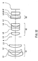
- FIG. 32 is a layout drawing showing the configuration of a zoom
lens according to an eighth embodiment of the present invention.
- FIG. 33 shows aberration diagrams for the wide-angle end, in the
standard state, of the zoom lens according to the eighth embodiment of
the present invention.
- FIG. 34 shows aberration diagrams for the intermediate focal
length (intermediate position), in the standard state, of the zoom lens
according to the eighth embodiment of the present invention.
- FIG. 35 shows aberration diagrams for the telescope end, in the
standard state, of the zoom lens according to the eighth embodiment of
the present invention.
- FIG. 36 shows aberration diagrams for the telescope end, in the
state where camera shake is corrected, of the zoom lens according to the
eighth embodiment of the present invention.
- FIG. 37 is a layout drawing showing the configuration of a zoom
lens according to a ninth embodiment of the present invention.
- FIG. 38 shows aberration diagrams for the wide-angle end, in the
standard state, of the zoom lens according to the ninth embodiment of
the present invention.
- FIG. 39 shows aberration diagrams for the intermediate focal
length (intermediate position), in the standard state, of the zoom lens
according to the ninth embodiment of the present invention.
- FIG. 40 shows aberration diagrams for the telescope end, in the
standard state, of the zoom lens according to the ninth embodiment of
the present invention.
- FIG. 41 shows aberration diagrams for the telescope end, in the
state where camera shake is corrected, of the zoom lens according to the
ninth embodiment of the present invention.
- FIG. 42 is a layout drawing showing the configuration of a zoom
lens according to a tenth embodiment of the present invention.
- FIG. 43 shows aberration diagrams for the wide-angle end, in the
standard state, of the zoom lens according to the tenth embodiment of
the present invention.
- FIG. 44 shows aberration diagrams for the intermediate focal
length (intermediate position), in the standard state, of the zoom lens
according to the tenth embodiment of the present invention.
- FIG. 45 shows aberration diagrams for the telescope end, in the
standard state, of the zoom lens according to the tenth embodiment of
the present invention.
- FIG. 46 shows aberration diagrams for the telescope end, in the
state where camera shake is corrected, of the zoom lens according to the
tenth embodiment of the present invention.
- FIG. 47 is a layout drawing showing the configuration of a zoom
lens according to an eleventh embodiment of the present invention.
- FIG. 48 shows aberration diagrams for the wide-angle end, in the
standard state, of the zoom lens according to the eleventh embodiment of
the present invention.
- FIG. 49 shows aberration diagrams for the intermediate focal
length (intermediate position), in the standard state, of the zoom lens
according to the eleventh embodiment of the present invention.
- FIG. 50 shows aberration diagrams for the telescope end, in the
standard state, of the zoom lens according to the eleventh embodiment of
the present invention.
- FIG. 51 shows aberration diagrams for the telescope end, in the
state where camera shake is corrected, of the zoom lens according to the
eleventh embodiment of the present invention.
- FIG. 52 diagrammatically shows the configuration of an
electronic still camera according to a twelfth embodiment of the present
invention.
-
Best Mode for Carrying Out the present invention
-
Hereinafter, the present invention is described in further detail
using embodiments.
First Embodiment
-
FIG. 1 is a layout drawing showing the configuration of a zoom
lens according to a first embodiment of the present invention.
-
As shown in FIG. 1, the zoom lens of this embodiment is made of
a first lens group G1 having a negative power, an aperture stop A, a
second lens group G2 having a positive power, and a third lens group G3
having a positive power, arranged in that order from the object side (left
side in FIG. 1) toward the image plane S side (right side in FIG. 1), and
includes eight lenses.
-
The first lens group G1 is made of a first lens L1 that is a
negative meniscus lens whose surface with strong curvature is facing the
image plane S, a second lens L2 that is a negative meniscus lens whose
surface with strong curvature is facing the image plane S, and a third
lens L3 that is a positive lens whose surface with strong curvature is
facing the object, arranged in that order from the object side.
-
The second lens group G2 is made of a fourth lens L4 that is a
plano-convex lens (positive lens) whose convex surface is facing the
object, a fifth lens L5 that is a positive lens, a sixth lens L6 that is a
negative lens, and a seventh lens L7 that is a biconvex lens, arranged in
that order from the object side. Here, the fifth lens L5 and the sixth
lens L6 are cemented. By cementing the fifth lens L5 and the sixth lens
L6, the overall length of the second lens group G2 can be shortened and
there is less decentered with regard to these two lenses during assembly.
Also, the sixth lens L6 and the seventh lens L7 are near one another at
the outer periphery of their effective diameter, although they are just
slightly separated.
-
The third lens group G3 is made of a single eighth lens L8 that is
a positive lens. Constituting the third lens group G3 by only a single
lens allows the overall length of the third lens group G3 to be shortened
and as a result the overall optical length of the zoom lens when collapsed
can be shortened.
-
The surface of the second lens L2 on the image plane S side is an
aspherical surface whose local curvature is monotonically reduced as
distance from the center increases and whose local curvature at the
effective diameter is negative. If all four surfaces of the first lens L1
and the second lens L2, which are both negative lenses, are spherical
surfaces, then a large negative distortion occurs at the wide-angle end
because the refracting power becomes excessively strong as the point of
incidence becomes farther from the center, however, if the surface of the
second lens L2 on the image plane S side is an aspherical surface like
that described above, then the refracting power can be kept from
becoming extremely strong even if the point of incidence is away from
the center, and thus negative distortion can be kept from occurring at the
wide-angle end. The object side surface of the fourth lens L4 is an
aspherical lens whose local radius of curvature increases monotonically
as distance from the center increases, within the range from the center
to the effective diameter. The object side surface of the seventh lens L7
is an aspherical surface whose local radius of curvature has a local
maximum in the range from the center to the effective diameter. The
surface of the fourth lens L4 on the image plane S side is flat. By
making the image plane S side surface of the fourth lens L4 a flat
surface, the fourth lens L4 can be easily positioned in the direction
perpendicular to the optical axis by attaching the fourth lens L4 after a
cemented lens of the fifth lens L5 and the sixth lens L6 is incorporated
into the lens barrel supporting the three lenses of the second lens group
G2 other than the parallel displaced lens element (seventh lens L7),
allowing the decenter of the lenses in the second lens group G2 to be
reduced even further. It should be noted that the seventh lens L7 is
configured so that the decentered aberration is small, even if it is
parallel displaced for the purpose of camera shake correction, and its
decenter tolerance is very large.
-
On the image plane S side of the zoom lens, an infrared cut filter,
an optical low-pass filter constituted by a quartz plate, and a solid-state
imaging element are arranged in that order from the object side, and a
cover glass for protection is attached to the solid-state imaging element.
In FIG. 1, the infrared cut filter, the optical low-pass filter, and the cover
glass are expressed as a single equivalent parallel plate element P. The
image of the subject captured by the zoom lens is formed on the
light-receiving surface (image plane) S of the solid-state imaging
element.
-
The first lens group G1 and the second lens group G2 can be
moved in the direction of the optical axis in order to change the combined
focal length of the overall lens system, and the third lens group G3 can
be moved in the direction of the optical axis for focus adjustment. The
aperture stop A can be moved as a single unit with the second lens group
G2 in the direction of the optical axis. Also, the seventh lens L7, which
is the lens of the second lens group G2 furthest to the image plane S side,
can be parallel displaced in the direction perpendicular to the optical
axis for camera shake correction. It should be noted that the aperture
stop A is not parallel displaced in the direction perpendicular to the
optical axis even if the seventh lens L7 is parallel displaced in the
direction perpendicular to the optical axis.
-
In this case, when the Abbe number of the seventh lens L7 at the
d-line is ν7, then it is preferable that the conditional expression
ν7 > 50
is satisfied.
-
When zooming from the wide-angle end to the telescope end, the
air gap between the first lens group G1 and the second lens group G2 is
reduced and the air gap between the second lens group G2 and the third
lens group G3 is increased. Cylindrical cams are used to move the first
lens group G1 and the second lens group G2 to a predetermined position
with the light-receiving surface (image plane) S of the solid-state
imaging element serving as a reference.
-
Focus adjustment is performed by keeping the first lens group G1
and the second lens group G2 stationary and shifting only the third lens
group G3 in the direction of the optical axis. In this case, the third lens
group G3 is moved toward the object as the shooting distance becomes
shorter. Because the third lens group G3 is made of a single lens and
the shifted portion, which includes other mechanism components that
are shifted, is lightweight, the third lens group G3 can be moved quickly
using a compact low-power motor.
-
There is only one lens, the seventh lens L7, that is parallel
displaced in the direction perpendicular to the optical axis for the
purpose of camera shake correction, and the shifted section, which
includes other mechanism components for parallel displacement of the
seventh lens L7, is lightweight, so that the seventh lens (parallel
displaced lens) L7 can be moved quickly using a compact low-power
actuator.
-
Giving the zoom lens shown in FIG. 1 a collapsing structure in
which the first lens group G1, the second lens group G2, and the third
lens group G3 are drawn toward the solid-state imaging element when
not in use allows the overall optical length after collapsing to be
shortened. A collapsing structure can be achieved by adding cam
grooves to the cylindrical cams for moving the first lens group G1 and
the second lens group G2 in the direction of the optical axis.
-
The zoom lens of this embodiment is configured so that the zoom
ratio at a shooting distance of ∞ is ×2.5 to ×3.2.
-
With the zoom lens of this embodiment, when the shooting
distance is ∞, fW is the combined focal length of the overall lens system
at the wide-angle end, fG2 is the combined focal length of the second lens
group G2, fG3 is the combined focal length of the third lens group G3, and
dL6 is the air gap between the sixth lens L6 and the seventh lens L7,
then it is preferable that the conditional expressions
2.2 < fG2 / fW < 2.8
4.0 < fG3 / fW < 7.0
0.05 < dL6 / fG2 < 0.15
are satisfied.
-
Also, in this case, when f4 is the focal length of the fourth lens L4
and f7 is the focal length of the seventh lens L7, then it is preferable that
the conditional expressions
0.9 < f4 / fG2 < 1.2
1.2 < f7 / fG2 < 1.7
are satisfied.
-
With the zoom lens of this embodiment, when mDT is the
magnification of the parallel displaced lens (seventh lens L7) at the
telescope end with the shooting distance at ∞, and mG3T is the
magnification of the third lens group G3 at the telescope end with the
shooting distance at ∞, then it is preferable that the conditional
expression
0.9 < (1 - mDT)mG3T < 1.3
is satisfied.
-
With the zoom lens of this embodiment, when n7 is the refractive
index of the seventh lens L7, r7F is the paraxial radius of curvature of its
surface on the object side, κ7F is the conic constant of its surface on the
object side, D7F is the fourth-order aspheric coefficient of its surface on
the object side, r7R is the paraxial radius of curvature of its surface on
the image plane side, κ7R is the conic constant of its surface on the image
plane side, D7R is the fourth-order aspheric coefficient of its surface on
the image plane side, and fT is the combined focal length of the overall
lens system at the telescope end when the shooting distance is ∞, then it
is preferable that B7 in Expression 4 below satisfies the conditions:
-0.7 < B7 < -1.5.
Expression 4 B7 = (n7 -1)(κ7F r7F 3 + 8D7F - κ7R r7R 3 - 8D7R)fT 3
-
Table 1 below shows specific examples of the numerical values of
the zoom lens shown in FIG. 1.
| Group | Element | Surface | r | d | nd | νd |
| G1 | L1 | 1 | 16.640 | 1.100 | 1.77250 | 49.6 |
| | 2 | 5.698 | 2.136 |
| L2 | 3 | 29.254 | 1.060 | 1.60602 | 57.8 |
| | 4 | 8.171* | 2.102 |
| L3 | 5 | 12.952 | 2.000 | 1.74077 | 27.8 |
| | 6 | 66.291 | variable |
| G2 | Stop | 7 | ∞ | 1.000 |
| L4 | 8 | 8.269* | 2.000 | 1.60602 | 57.8 |
| | 9 | ∞ | 1.355 |
| L5 | 10 | 9.932 | 2.204 | 1.69680 | 55.5 |
| L6 | 11 | 51.280 | 0.910 | 1.80518 | 25.5 |
| | 12 | 5.653 | 1.000 |
| L7 | 13 | 16.390* | 1.700 | 1.60602 | 57.8 |
| | 14 | -30.168 | variable |
| G3 | L8 | 15 | 19.235 | 1.560 | 1.51680 | 64.2 |
| | 16 | -152.973 | variable |
| P | 17 | ∞ | 2.260 | 1.51680 | 64.2 |
| 18 | ∞ |
-
The unit of length in the table is [mm]. In Table 1, r is the
radius of curvature of the lens, d is the distance between surfaces, and nd
and νd are the refractive index and the Abbe number at the d-line of the
lens, respectively (the same applies for other embodiments described
later). It should be noted that surfaces with an * mark are aspheric,
and that their aspheric shape is defined by Expression 5 shown below
(the same applies for other embodiments described later).
Expression 5 z = h2/r1 + 1 - (1 + κ)(h/r)2 + Dh4 + Eh6 + Fh8 + Gh10
-
In Expression 5 shown above, h is the height from the optical axis,
z is the sag amount at the point on the aspherical surface where the
height from the optical axis is h, κ is the conic constant, and D, E, F, and
G are the fourth-order, sixth-order, eighth-order, and tenth-order
aspheric coefficients, respectively.
-
Table 2 below shows the aspheric coefficients of the zoom lens
shown in FIG. 1.
| | Fourth Surface | Eighth Surface | Thirteenth Surface |
| κ | -5.27532×10⁻¹ | -8.36550×10⁻² | 0.0 |
| D | -3.88830×10⁻⁴ | -1.46408×10⁻⁴ | -6.85762×10⁻⁵ |
| E | -9.97691×10⁻⁶ | -8.93905×10⁻⁷ | -6.24238×10⁻⁶ |
| F | 1.91208×10⁻⁷ | -1.30355×10⁻⁷ | 1.67948×10⁻⁷ |
| G | -1.14300×10⁻⁸ | 3.91244×10⁻⁹ | 3.26910×10⁻⁸ |
-
Table 3 below shows the variable distance between surfaces (in
mm) in a case where the shooting distance of the zoom lens shown in FIG.
1 is ∞. In Table 3, f (mm) and 2ω represent the focal length and the
angle of view, respectively (the same applies for other embodiments
described later).
| Surface Spacing | Wide-angle End | Intermediate Position | Telescope End |
| d6 | 17.139 | 6.924 | 1.036 |
| d14 | 4.768 | 9.701 | 18.306 |
| d16 | 1.400 | 1.455 | 1.497 |
| f | 5.300 | 9.180 | 15.900 |
| F value | 2.76 | 3.50 | 4.85 |
| 2ω | 63.86° | 38.84° | 22.80° |
-
Here, when fw is the combined focal length of the wide-angle end
and fT is the combined focal length of the telescope end with the shooting
distance at ∞, then fN that satisfies the relationship of Expression 6
below is called the "intermediate focal length."
Expression 6 fN = fWfT
-
FIGs. 2 to 4 are aberration diagrams (spherical aberration,
astigmatism, and distortion) of the zoom lens shown in FIG. 1 when the
aperture stop is open and the shooting distance is ∞. FIG. 2 is the case
for the wide-angle end, FIG. 3 is the case for the intermediate focal
length (intermediate position), and FIG. 4 is the case for the telescope
end. It should be noted that in the spherical aberration diagrams, the
solid line indicates values at the d-line, the short broken line indicates
values at the F-line, and the long broken line indicates values at the
C-line. Also, in the astigmatism diagrams, the solid line indicates the
sagittal curvature of field and the broken line indicates the meridional
curvature of field (the same applies for other embodiments described
later).
-
It is clear from the aberration diagrams shown in FIGs. 2 to 4
that the zoom lens of this embodiment demonstrates good aberration
properties even if the zoom position is changed as the shooting distance
changes.
-
FIG. 5 shows the aberration diagrams during a camera shake
correction at the telescope end. FIG. 5 shows the transverse aberration
at an image point on the axis and at the image points of ± 75% of the
maximum image height in a case where the shooting distance is ∞, the
aperture stop is open, and the seventh lens L7 of the second lens group
G2 has been parallel displaced by 0.113 mm in the direction
perpendicular to the optical axis. Here the solid line indicates values at
the d-line, the short broken line indicates values at the F-line, and the
long broken line indicates values at the C-line. It should be noted that
in FIG. 5, the meridional plane is the plane that includes the optical axis
of the first lens group G1 and the optical axis of the parallel displaced
lens (seventh lens L7).
-
The amount of image decenter with a shooting distance of ∞, at
the telescope end, in a case where the zoom lens is tilted 0.5° is
equivalent to the amount of image decenter when the seventh lens L7 of
the second lens group G2 is parallel displaced by 0.113 mm in the
direction perpendicular to the optical axis.
-
It is clear from the aberration diagrams of FIG. 5 that there is
good symmetry in the transverse aberration at the image point on the
axis. Comparing the transverse aberration at the image point of 75% of
the maximum image height and the transverse aberration at the image
point of -75% of the maximum image height, from the fact that they both
have a small degree of curvature and the slopes of their aberration
curves are substantially equal it is clear that there is little decentered
coma and decentered astigmatism. This means that sufficient
image-forming properties are obtained even when the camera shake has
been corrected. Also, if the camera shake angle of the zoom lens is the
same, then the amount of parallel displacement of the seventh lens L7 of
the second lens group G2 that is required for camera shake correction is
reduced as the combined focal length of the overall lens system becomes
shorter. Consequently, regardless of the zoom position, sufficient
camera shake correction is possible for camera shake angles up to 0.5°.
-
As the solid-state imaging element of the zoom lens shown in FIG.
1, it is possible to use an element whose effective pixel number is 1600
(horizontal) × 1200 (vertical), whose pixel pitch is 3.2 µm (horizontal) ×
3.2 µm (vertical), and whose effective picture size is 5.12 mm (horizontal)
× 3.84 mm (vertical). As the solid-state imaging element, it is also
possible to use an element in which a miniature positive lens is provided
at each pixel in order to increase the effective aperture ratio.
-
As described above, the zoom lens shown in FIG. 1, with a zoom
ratio of ×3.0 and an angle of view at the wide-angle end of approximately
64° , has high resolution and a short overall optical length when not in
use, and is moreover provided with a camera shake-correction function,
and the image-forming properties when camera shake correction is
performed are also good.
-
It goes without saying that a zoom lens having the configuration
shown in FIG. 1 but in which the seventh lens L7 is not parallel
displaced in the direction perpendicular to the optical axis is also
effective. Using common components for most of the components
making up the lens unit, it is possible to achieve a zoom lens that has
been configured so that the seventh lens L7 is parallel displaced in the
direction perpendicular to the optical axis and a zoom lens in which the
seventh lens L7 is not parallel displaced in the direction perpendicular to
the optical axis.
Second Embodiment
-
FIG. 6 is a layout drawing showing the configuration of a zoom
lens according to the second embodiment of the present invention.
-
As shown in FIG. 6, the zoom lens of this embodiment is made of
a first lens group G1 having a negative power, an aperture stop A, a
second lens group G2 having a positive power, and a third lens group G3
having a positive power, arranged in that order from the object side (left
side in FIG. 6) toward the image plane S side (right side in FIG. 6), and
includes eight lenses.
-
The zoom lens shown in FIG. 6 has the same configuration as the
zoom lens detailed above in the first embodiment (see FIG. 1), and is
different only in the manner in which the seventh lens L7 is provided
with an aspherical surface. That is, in the zoom lens shown in FIG. 1,
the surface of the seventh lens L7 that is on the object side is an
aspherical surface, whereas in the zoom lens according to this
embodiment and shown in FIG. 6, the surface of the seventh lens L7 that
is on the image plane S side is an aspherical surface. More specifically,
the surface of the seventh lens L7 on the image plane S side is an
aspherical surface whose local radius of curvature has a local minimum
value within the range from its center to the effective diameter.
-
It is preferable that the various conditions set forth in
Conditional Expressions (13) to (20) are satisfied in this embodiment as
well.
-
Table 4 below shows specific examples of the numerical values of
the zoom lens shown in FIG. 6, Table 5 below shows the aspheric
coefficients of the zoom lens, and Table 6 below shows the variable
distance between surfaces (in mm) in a case where the shooting distance
of the zoom lens is ∞.
| Group | Element | Surface | r | d | nd | νd |
| G1 | L1 | 1 | 14.509 | 1.100 | 1.77250 | 49.6 |
| | 2 | 5.731 | 2.228 |
| L2 | 3 | 49.402 | 1.060 | 1.60602 | 57.8 |
| | 4 | 8.567* | 2.162 |
| L3 | 5 | 13.079 | 2.000 | 1.74077 | 27.8 |
| | 6 | 63.330 | variable |
| G2 | Stop | 7 | ∞ | 1.000 |
| L4 | 8 | 8.297* | 2.000 | 1.60602 | 57.8 |
| | 9 | ∞ | 1.216 |
| L5 | 10 | 9.349 | 2.227 | 1.69680 | 55.5 |
| L6 | 11 | 40.370 | 0.910 | 1.80518 | 25.5 |
| | 12 | 5.412 | 1.000 |
| L7 | 13 | 14.782 | 1.700 | 1.60602 | 57.8 |
| | 14 | -37.989* | variable |
| G3 | L8 | 15 | 19.235 | 1.560 | 1.51680 | 64.2 |
| | | 16 | -152.973 | variable |
| P | 17 | ∞ | 2.260 | 1.51680 | 64.2 |
| 18 | ∞ |
| | Fourth Surface | Eighth Surface | Fourteenth Surface |
| κ | -3.52447×10⁻¹ | -9.16294×10⁻² | 0.0 |
| D | -3.61595×10⁻⁴ | -1.41292×10⁻⁴ | 7.70937×10⁻⁵ |
| E | -1.06755×10⁻⁵ | -5.99004×10⁻⁷ | -5.76775×10⁻⁶ |
| F | 3.65593×10⁻⁷ | -2.10559×10⁻⁷ | 1.61394×10⁻⁶ |
| G | -1.52518×10⁻⁸ | 9.17323×10⁻⁹ | -1.34706×10⁻⁷ |
| Surface Spacing | Wide-angle End | Intermediate Position | Telescope End |
| d6 | 17.174 | 6.932 | 1.025 |
| d14 | 4.512 | 9.330 | 17.718 |
| d16 | 1.400 | 1.446 | 1.493 |
| f | 5.300 | 9.180 | 15.900 |
| F value | 2.75 | 3.47 | 4.80 |
| 2ω | 63.86° | 38.84° | 22.80° |
-
FIGs. 7 to 9 are aberration diagrams (spherical aberration,
astigmatism, and distortion) of the zoom lens shown in FIG. 6 when the
shooting distance is ∞ and the aperture stop is open. FIG. 7 shows the
case for the wide-angle end, FIG. 8 shows the case for the intermediate
position, and FIG. 9 shows the case for the telescope end.
-
It is clear from the aberration diagrams shown in FIGs. 7 to 9
that the zoom lens of this embodiment demonstrates good aberration
properties even if the zoom position is changed as the shooting distance
changes.
-
FIG. 10 shows the aberration diagrams during a camera shake
correction at the telescope end. FIG. 10 shows the transverse
aberration at an image point on the axis and at the image points of ±
75% of the maximum image height in a case where the shooting distance
is ∞, the aperture stop is open, and the seventh lens L7 of the second
lens group G2 has been parallel displaced by 0.115 mm in the direction
perpendicular to the optical axis. The conditions and denotations for
FIG. 10 are the same as those of FIG. 5 of the first embodiment.
-
The amount of image decenter with a shooting distance of ∞, at
the telescope end, in a case where the zoom lens is tilted 0.5° is
equivalent to the amount of image decenter when the seventh lens L7 of
the second lens group G2 is parallel displaced by 0.115 mm in a direction
perpendicular to the optical axis.
-
It is clear from the aberration diagrams of FIG. 10 that, like in
the first embodiment, sufficient camera shake correction is possible for
camera shake angles of the zoom lens up to 0.5°.
-
The same solid-state imaging elements as those described above
in the first embodiment can be used in the zoom lens shown in FIG. 6.
-
As described above, the zoom lens shown in FIG. 6, with a zoom
ratio of 3.0 times and an angle of view at the wide-angle end of
approximately 64° , has high resolution and a short overall optical
length when not in use, and is moreover provided with a camera
shake-correction function, and the image-forming properties when
camera shake correction is performed are also good.
Third Embodiment
-
FIG. 11 is a layout drawing showing the configuration of a zoom
lens according to a third embodiment of the present invention.
-
The zoom lens shown in FIG. 11 has the same configuration as
the zoom lens detailed above in the second embodiment (see FIG. 6), and
is different only in the manner in which the first lens group G1 is
provided with aspherical surfaces. That is, in the first lens group G1 of
the zoom lens shown in FIG. 6, the surface of the second lens L2 on the
image plane S side is an aspherical surface, whereas in the first lens
group G1 of the zoom lens according to this embodiment and shown in
FIG. 11, the surface of the first lens L1 on the image plane S side is an
aspherical surface. More specifically, the surface of the second lens L2
on the image plane S side is an aspherical surface whose local radius of
curvature monotonically increases within the range from its center to the
effective diameter.
-
It is preferable that the various conditions set forth in
Conditional Expressions (13) to (20) are satisfied in this embodiment as
well.
-
Table 7 below shows specific examples of the numerical values of
the zoom lens shown in FIG. 11, Table 8 below shows the aspheric
coefficients of the zoom lens, and Table 9 below shows the variable
distance between surfaces (in mm) in a case where the shooting distance
of the zoom lens is ∞.
| Group | Element | Surface | r | d | nd | νd |
| G1 | L1 | 1 | 20.216 | 1.100 | 1.60602 | 57.8 |
| | 2 | 6.009* | 2.232 |
| L2 | 3 | 126.054 | 1.060 | 1.69680 | 55.5 |
| | 4 | 10.493 | 2.358 |
| L3 | 5 | 12.417 | 2.000 | 1.74077 | 27.8 |
| | 6 | 39.817 | variable |
| G2 | Stop | 7 | ∞ | 1.000 |
| L4 | 8 | 7.452* | 2.000 | 1.60602 | 57.8 |
| | 9 | ∞ | 1.123 |
| L5 | 10 | 10.278 | 1.800 | 1.69680 | 55.5 |
| L6 | 11 | 33.095 | 0.910 | 1.80518 | 25.5 |
| | 12 | 5.378 | 1.000 |
| L7 | 13 | 15.186 | 1.700 | 1.60602 | 57.8 |
| | 14 | -35.466* | variable |
| G3 | L8 | 15 | 19.169 | 1.560 | 1.51680 | 64.2 |
| | | 16 | -142.445 | variable |
| P | 17 | ∞ | 2.260 | 1.51680 | 64.2 |
| 18 | ∞ |
| | Second Surface | Eighth Surface | Fourteenth Surface |
| κ | -1.68190×10⁻¹ | -8.22580×10⁻² | 0.0 |
| D | -1.21997×10⁻⁴ | -1.97935×10⁻⁴ | 7.30266×10⁻⁵ |
| E | -7.99844×10⁻⁶ | -4.64920×10⁻⁷ | 3.24000×10⁻⁶ |
| F | 2.62630×10⁻⁷ | -3.66489×10⁻⁷ | 4.58094×10⁻⁷ |
| G | -9.14433×10⁻⁹ | 1.76843×10⁻⁸ | -6.53756×10⁻⁸ |
| Surface Spacing | Wide-angle End | Intermediate Position | Telescope End |
| d6 | 17.161 | 6.913 | 1.000 |
| d14 | 4.701 | 9.502 | 17.851 |
| d16 | 1.400 | 1.439 | 1.486 |
| f | 5.300 | 9.180 | 15.900 |
| F value | 2.79 | 3.55 | 4.91 |
| 2ω | 63.88° | 38.80° | 22.80° |
-
FIGs. 12 to 14 are aberration diagrams (spherical aberration,
astigmatism, and distortion) of the zoom lens shown in FIG. 11 when the
shooting distance is ∞ and the aperture stop is open. FIG. 12 shows the
case for the wide-angle end, FIG. 13 shows the case for the intermediate
position, and FIG. 14 shows the case for the telescope end.
-
It is clear from the aberration diagrams shown in FIGs. 12 to 14
that the zoom lens of this embodiment demonstrates good aberration
properties even if the zoom position is changed as the shooting distance
changes.
-
FIG. 15 shows the aberration diagrams during a camera shake
correction at the telescope end. FIG. 15 shows the transverse
aberration at an image point on the axis and at the image points of ±
75% of the maximum image height in a case where the shooting distance
is ∞, the aperture stop is open, and the seventh lens L7 of the second
lens group G2 has been parallel displaced by 0.115 mm in the direction
perpendicular to the optical axis. The conditions and denotations for
FIG. 15 are the same as those of FIG. 5 of the first embodiment.
-
The amount of image decenter with a shooting distance of ∞, at
the telescope end, in a case where the seventh lens L7 of the second lens
group G2 is parallel displaced by a parallel displacement amount of
0.115 mm corresponds to the amount of image decenter when the zoom
lens is tilted 0.5°.
-
It is clear from the aberration diagrams of FIG. 15 that, like in
the first embodiment, sufficient camera shake correction is possible for
camera shake angles of the zoom lens up to 0.5°.
-
The same solid-state imaging elements as those described above
in the first embodiment can be used in the zoom lens shown in FIG. 11.
-
As described above, the zoom lens shown in FIG. 11, with a zoom
ratio of 3.0 times and an angle of view at the wide-angle end of
approximately 64° , has high resolution and a short overall optical
length when not in use, and is moreover provided with a camera
shake-correction function, and the image-forming properties when
camera shake correction is performed are also good.
Fourth Embodiment
-
FIG. 16 is a layout drawing showing the configuration of a zoom
lens according to a fourth embodiment of the present invention.
-
The zoom lens shown in FIG. 16 has a third lens group G3 with a
configuration different than that in the zoom lens detailed in the first
embodiment (see FIG. 1), however, it is the same in all other aspects.
That is, in the zoom lens shown in FIG. 1, the third lens group G3 is
made of a single lens, the eighth lens L8, which is a positive lens,
whereas in the zoom lens according to this embodiment and shown in
FIG. 16, the third lens group G3 is made of a cemented lens in which an
eighth lens L8 that is a negative meniscus lens and a ninth lens L9 that
is a biconvex lens are cemented. Constituting the third lens group G3
by cementing a positive lens and a negative lens, it is possible to shorten
the overall length of the third lens group G3 and by extension shorten
the overall optical length when collapsed.
-
It is preferable that the various conditions set forth in
Conditional Expressions (13) to (20) are satisfied in this embodiment as
well.
-
Table 10 below shows specific examples of the numerical values of
the zoom lens shown in FIG. 16, Table 11 below shows the aspheric
coefficients of the zoom lens, and Table 12 below shows the variable
distance between surfaces (in mm) in a case where the shooting distance
of the zoom lens is ∞.
| Group | Element | Surface | r | d | nd | νd |
| G1 | L1 | 1 | 17.504 | 1.200 | 1.77250 | 49.6 |
| | 2 | 5.605 | 2.232 |
| L2 | 3 | 24.225 | 1.100 | 1.60602 | 57.8 |
| | 4 | 9.563* | 2.361 |
| L3 | 5 | 14.726 | 2.200 | 1.74077 | 27.8 |
| | 6 | 63.688 | variable |
| G2 | Stop | 7 | ∞ | 1.500 |
| L4 | 8 | 8.944* | 2.000 | 1.66549 | 55.4 |
| | 9 | ∞ | 1.252 |
| L5 | 10 | 10.015 | 2.227 | 1.69680 | 55.5 |
| L6 | 11 | 37.148 | 0.980 | 1.80518 | 25.5 |
| | 12 | 5.577 | 1.016 |
| L7 | 13 | 18.019* | 1.800 | 1.60602 | 57.8 |
| | 14 | -38.568 | variable |
| G3 | L8 | 15 | 22.249 | 0.600 | 1.69895 | 30.1 |
| L9 | 16 | 11.476 | 1.900 | 1.69680 | 55.5 |
| | 17 | -91.910 | variable |
| P | 18 | ∞ | 2.260 | 1.51680 | 64.2 |
| 19 | ∞ |
| | Fourth Surface | Eighth Surface | Thirteenth Surface |
| κ | -6.89155×10⁻¹ | -2.75623×10⁻¹ | 0.0 |
| D | -3.85337×10⁻⁴ | -9.39764×10⁻⁵ | -3.98965×10⁻⁵ |
| E | -1.18548×10⁻⁵ | 6.06321×10⁻⁷ | 1.91400×10⁻⁶ |
| F | 3.37090×10⁻⁷ | -1.07678×10⁻⁷ | -4.94309×10⁻⁷ |
| G | -1.71152×10⁻⁸ | 1.37704×10⁻⁹ | 6.45013×10⁻⁸ |
| Surface Spacing | Wide-angle End | Intermediate Position | Telescope End |
| d6 | 16.998 | 6.722 | 0.800 |
| d14 | 4.650 | 9.969 | 19.257 |
| d16 | 1.200 | 1.278 | 1.365 |
| f | 5.300 | 9.180 | 15.900 |
| F value | 2.75 | 3.53 | 4.93 |
| 2ω | 63.84° | 38.82° | 22.80° |
-
In the third lens group G3, to favorably correct the curvature of
field and chromatic aberration, it is possible to lower the refractive index
of the eighth lens L8 so as to reduce its Abbe number, or to raise the
refractive index of the ninth lens L9 so as to increase its Abbe number.
However, if the ratio of the Abbe number of the eighth lens L8 to the
Abbe number of the ninth lens L9 is large, then the center thickness of
the ninth lens L9 becomes thick in order to secure thickness at the edges,
and attention must be paid to the weight of the third lens group G3.
-
FIGs. 17 to 19 are aberration diagrams (spherical aberration,
astigmatism, and distortion) of the zoom lens shown in FIG. 16 when the
shooting distance is ∞ and the aperture stop is open. FIG. 17 shows the
case for the wide-angle end, FIG. 18 shows the case for the intermediate
position, and FIG. 19 shows the case for the telescope end.
-
It is clear from the aberration diagrams shown in FIGs. 17 to 19
that the zoom lens of this embodiment demonstrates good aberration
properties even if the zoom position is changed as the shooting distance
changes.
-
FIG. 20 shows the aberration diagrams during a camera shake
correction at the telescope end. FIG. 20 shows the transverse
aberration at an image point on the axis and at the image points of ±
75% of the maximum image height in a case where the shooting distance
is ∞, the aperture stop is open, and the seventh lens L7 of the second
lens group G2 has been parallel displaced by 0.131 mm in the direction
perpendicular to the optical axis. The conditions and denotations for
FIG. 20 are the same as those of FIG. 5 of the first embodiment.
-
The amount of image decenter at a shooting distance of ∞, at the
telescope end, in a case where the seventh lens L7 of the second lens
group G2 is parallel displaced by a parallel displacement amount of
0.131 mm corresponds to the amount of image decenter when the zoom
lens is tilted 0.5°.
-
It is clear from the aberration diagrams of FIG. 20 that, like in
the first embodiment, sufficient camera shake correction is possible for
camera shake angles of the zoom lens up to 0.5°.
-
The same solid-state imaging elements as those described above
in the first embodiment can be used in the zoom lens shown in FIG. 16.
-
As described above, the zoom lens shown in FIG. 16, with a zoom
ratio of 3.0 times and an angle of view at the wide-angle end of
approximately 64° , has high resolution and a short overall optical
length when not in use, and is moreover provided with a camera
shake-correction function, and the image-forming properties when
camera shake correction is performed are also good.
-
Table 13 below shows the main parameters and the numerical
values of the conditional expressions detailed above for the first through
fourth embodiments described above.
| Conditional Expression | Embodiments |
| | 1 | 2 | 3 | 4 |
| fG2/fW | 2.416 | 2.389 | 2.385 | 2.516 |
| fG3/fW | 6.257 | 6.257 | 6.189 | 4.906 |
| dL6/fG2 | 0.078 | 0.079 | 0.079 | 0.076 |
| f4/fG2 | 1.066 | 1.081 | 0.973 | 1.008 |
| f7/fG2 | 1.388 | 1.404 | 1.406 | 1.539 |
| (1-mDT)mG3T | 1.226 | 1.202 | 1.206 | 1.059 |
| B7 | -1.205 | -1.339 | -1.423 | -0.782 |
| ν7 | 57.8 | 57.8 | 57.8 | 57.8 |
Fifth Embodiment
-
FIG. 21 is a diagrammatic structural diagram showing the
electronic still camera according to a fifth embodiment of the present
invention.
-
In FIG. 21, the reference numeral 12 denotes a zoom lens, 14
denotes a solid-state imaging element, 15 denotes a liquid crystal
monitor, 18 denotes a first lens group, 19 denotes an aperture stop, 20
denotes a second lens group, 21 denotes a third lens group, and 23
denotes a parallel displaced lens.
-
The zoom lens 12 is arranged on the front side of a housing 11,
and to the rear of the zoom lens 12 are arranged an optical low-pass
filter 13 and the solid-state imaging element 14 in that order from the
object side to the image plane side. The liquid crystal monitor 15 is
arranged at the rear side of the housing 11, and the solid-state imaging
element 14 and the liquid crystal monitor 15 are near one another.
-
The optical low-pass filter 13 has a configuration in which a first
quartz plate, a second quartz plate, and a third quartz plate are
cemented by a transparent adhesive and arranged in that order from the
object side to the image plane side. The three quartz plates are parallel
flat plates and the optic axes of the quartz plates are tilted 45° with
respect to the optical axis. Also, seen from the zoom lens 12, the
directions in which the optic axes of the quartz plates are projected onto
a light-receiving surface 17 of the solid-state imaging element 14 are for
the first quartz plate a direction rotated 45° to the left from the image
horizontal direction, for the second quartz plate a direction rotated 45° to
the right from the image horizontal direction, and for the third quartz
plate the image horizontal direction. The optical low-pass filter 13
prevents error signals such as moiré due to the pixel structure of the
solid-state imaging element 14. An optical multilayer film that reflects
infrared light but allows light in the visible spectrum to pass is vapor
deposited onto the object-side surface of the low-pass filter 13.
-
The solid-state imaging element 14 has an effective pixel number
of 1600 (horizontal) × 1200 (vertical), a pixel pitch of 3.2 µm (horizontal)
× 3.2 µm (vertical), and an effective image size of 5.12 mm (horizontal) ×
3.84 mm (vertical), and each pixel is provided with a miniature positive
lens. A cover glass 16 is provided on the object-side of the solid-state
imaging element 14. The image of the subject obtained by the zoom lens
12 is formed on the light-receiving surface 17.
-
In this embodiment, the zoom lens shown in FIG. 1 is used as the
zoom lens 12. The zoom lens 12 is made of a first lens group 18, an
aperture stop 19, a second lens group 20, and a third lens group 21,
arranged in that order from the object side to the image plane side. The
second lens group 20 is made of a lens group 22 that is not parallel
displaced in the direction perpendicular to the optical axis and a parallel
displaced lens 23 that is arranged on the image plane side of the lens
group 22 and that can be parallel displaced.
-
The first lens group 18 is attached to a moving lens barrel 24.
The lens group 22, which is not parallel displaced, of the second lens
group 20 is attached to a member 25 that can be moved in the direction
of the optical axis. The parallel displaced lens 23 is attached to a
member 26 that can be parallel displaced in the direction perpendicular
to the optical axis, and the member 26 is attached to the member 25.
The aperture stop 19 is attached to the object-side of the member 25.
By adopting this configuration, the aperture stop 19 can be shifted in the
optical axis direction as a single unit with the second lens group 20, and
during camera shake correction it is possible to parallel displace only the
parallel displaced lens 23 in the direction perpendicular to the optical
axis.
-
The moving lens barrel 24 and the member 25 are incorporated
into a main lens barrel 27, and can be moved in the direction of the
optical axis. The moving lens barrel 24 and the member 25 can be
moved in the direction of the optical axis in such a manner that their
position with respect to the solid-state imaging element 14 satisfies a
predetermined relationship by rotating a cylindrical cam 28 that is
attached to the outside of the main lens barrel 27, thereby allowing the
combined focal length of the overall lens system to be changed. In the
case of changing from the wide-angle end to the telescope end, the first
lens group 18 projects toward the object after it has been retreated
toward the image plane, and the second lens group 20 is monotonically
moved from the image plane side to the object side.
-
The third lens group 21 can be moved in the direction of the
optical axis by a motor. By detecting the position at which
high-frequency components of the captured image become a peak while
moving the third lens group 21 in the direction of the optical axis by the
motor and then moving the third lens group 21 to that position, it is
possible to carry out automatic focus adjustment.
-
By adopting a collapsed configuration in which the first lens
group 18, the member 25, and the third lens group 21 are each drawn
toward the image plane (toward the solid-state imaging element 14)
when not in use, it is possible to shorten the overall optical length of the
zoom lens when not in use (when collapsed). A mechanism for drawing
the first lens group 18 and the member 25 toward the image plane can be
achieved by extending the cam grooves of the cylindrical cam 27.
-
If the zoom lens is tilted due to camera shake, then by parallel
displacing the parallel displaced lens 23 by a predetermined amount
using an actuator of shifting in the image horizontal direction and an
actuator for shifting in the image vertical direction, it is possible perform
camera shake correction. For example, if the zoom lens is tilted due to
camera shake so that its object side drops, then camera shake correction
can be performed by parallel displacing the parallel displaced lens 23
upward by a predetermined amount using the actuator for parallel
displacing in the image vertical direction. To perform camera shake
correction requires means for detecting the camera shake angle of the
zoom lens in the image horizontal direction, the camera shake angle in
the image vertical direction, the magnification of the parallel displaced
lens 23, and the magnification of the third lens group 21. Two angle
velocity sensors (camera shake detection means) can be used to detect
the two camera shake angles, and a position detection sensor for
determining the positions of the second lens group 20 and the third lens
group 21 with respect to the solid-state imaging element 14 can be used
to detect the magnification of the parallel displaced lens 23 and the
magnification of the third lens group 21. In this case, it is possible to
calculate by microcomputer the camera shake angles of the two
directions, the magnification of the parallel displaced lens 23, and the
magnification of the third lens group 21 based on the output of these
sensors, generate the required control signals, and input these control
signals to the actuators.
-
As described above, it is possible to provide an electronic still
camera whose zoom ratio is ×2.5 to ×3.2, whose angle of view at the
wide-angle end is approximately 60°, and which has high resolution and
is thin in the depth direction when not in use.
-
The electronic still camera described above can be provided with
an electronic zoom function for using a signal processing circuit to
magnify to the entire picture the image that is formed in the center of
the solid-state imaging element, and when the electronic zoom function
is used the effects due to the camera shake correction function can be
noticeably obtained, as described below.
-
The extent of blurring due to camera shake when the zoom lens is
tilted due to camera shake can be assessed using the ratio of the amount
of image decenter to the diagonal length of the solid-state imaging
element (the image decenter amount ratio). This ratio is constant
regardless of the size at which printing is performed from signals of the
captured image. The diagonal length of the captured image if the
electronic zoom function is not used matches the diagonal length of the
effective region of the solid-state imaging element, but the diagonal
length of the captured image when the electronic zoom function is used is
smaller than the diagonal length of the solid-state imaging element.
Consequently, when the electronic zoom function is used in a case where
the image decenter amount is constant, the image decenter amount ratio
increases, raising the extent of the camera shake blurriness.
-
When the camera shake correction function is used the image
decenter amount becomes extremely small, so that the image decenter
amount ratio becomes smaller and blurriness due to camera shake is
significantly improved even if the electronic zoom function is used.
-
It should be noted that the zoom lens according to the first
embodiment was used in the electronic still camera shown in FIG. 21,
however, any of the zoom lenses according to the second through fourth
embodiments may be used in place of the zoom lens of the first
embodiment. Also, an electronic still camera without the camera shake
correction function is also extremely useful as an electronic still camera.
-
The optical system of the electronic still camera shown in FIG. 21
can also be used in video cameras designed for moving pictures. In this
case, it is possible to capture not only moving pictures but also still
pictures at high resolution.
Sixth Embodiment
-
FIG. 22 is a layout drawing showing the configuration of a zoom
lens according to a sixth embodiment of the present invention.
-
As shown in FIG. 22, the zoom lens of this embodiment is made of
a first lens group G1 having a negative power, an aperture stop A, a
second lens group G2 having a positive power, and a third lens group G3
having a positive power, arranged in that order from the object side (left
side in FIG. 22) toward the image plane S side (right side in FIG. 22),
and includes eight lenses.
-
The first lens group G1 is made of a first lens L1 that is a
negative meniscus lens whose surface with strong curvature is facing the
image plane S, a second lens L2 that is a negative meniscus lens whose
surface with strong curvature is facing the image plane S, and a third
lens L3 that is a positive lens whose surface with strong curvature is
facing the object, arranged in that order from the object side.
-
The second lens group G2 is made of a fourth lens L4 that is a
plano-convex lens (positive lens) whose convex surface is facing the
object, a fifth lens L5 that is a positive lens, a sixth lens L6 that is a
negative lens, and a seventh lens L7 that is a positive lens, arranged in
that order from the object side. Here, the fifth lens L5 and the sixth
lens L6 are cemented. By cementing the fifth lens L5 and the sixth lens
L6, the overall length of the second lens group G2 can be shortened and
there is less decenter with regard to these two lenses during assembly.
Also, the sixth lens L6 and the seventh lens L7 are in contact at the
outer periphery of their effective diameter.
-
The third lens group G3 is made of a single eighth lens L8 that is
a positive lens. Constituting the third lens group G3 by only a single
lens allows the overall length of the third lens group G3 to be shortened
and as a result the overall optical length when collapsed can be
shortened.
-
The surface of the second lens L2 on the image plane S side is an
aspherical surface whose local curvature of radius is monotonically
increased as distance from the center increases. The surface of the
fourth lens L4 on the object side is an aspherical surface whose local
curvature of radius is monotonically increased as distance from the
center increases. The surface of the seventh lens L7 on the image plane
S side is an aspherical surface whose local curvature of radius is
monotonically decreased as distance from the center increases. The
surface of the fourth lens L4 on the image plane S side is a flat surface.
-
On the image plane S side of the zoom lens, an infrared cut filter,
an optical low-pass filter constituted by a quartz plate, and a solid-state
imaging element are arranged in that order from the object side, and a
cover glass for protection is attached to the solid-state imaging element.
In FIG. 22, the infrared cut filter, the optical low-pass filter, and the
cover glass are expressed as a single equivalent parallel plate element P.
An image of the subject captured by the zoom lens is formed on the
light-receiving surface (image plane) S of the solid-state imaging
element.
-
The first lens group G1 and the second lens group G2 can be
moved in the direction of the optical axis in order to change the combined
focal length of the overall lens system, and the third lens group G3 can
be moved in the direction of the optical axis for focus adjustment. The
aperture stop A can be moved as a single unit with the second lens group
G2 in the direction of the optical axis. Also, the second lens group G2
can be parallel displaced in a direction perpendicular to the optical axis
for camera shake correction. It should be noted that parallel
displacement of the aperture stop A in the direction perpendicular to the
optical axis does not occur even if there is parallel displacement of the
second lens group G2 in the direction perpendicular to the optical axis.
-
When zooming from the wide-angle end to the telescope end, the
air gap between the first lens group G1 and the second lens group G2 is
reduced and the air gap from the second lens L2 to the third lens group
G3 is increased. Cylindrical cams are used to move the first lens group
G1 and the second lens group G2 to a predetermined position with the
light-receiving surface (image plane) S of the solid-state imaging element
serving as a reference.
-
Focus adjustment is performed by keeping the first lens group G1
and the second lens group G2 stationary and shifting only the third lens
group G3 in the direction of the optical axis. In this case, the third lens
group G3 is moved toward the object as the shooting distance becomes
shorter. Because the third lens group G3 is made of a single lens and
the shifted portion, which includes other mechanism components that
are shifted, is light in weight, the third lens G3 can be moved at high
speeds using a compact low-power motor.
-
Giving the zoom lens shown in FIG. 22 a collapsing structure in
which the first lens group G1, the second lens group G2, and the third
lens group G3 are drawn toward the solid-state imaging element when
not in use allows the overall optical length after collapsing to be
shortened. A collapsing structure can be achieved by adding cam
grooves to the cylindrical cams for shifting the first lens group G1 and
the second lens group G2 in the direction of the optical axis.
-
The zoom lens of this embodiment is configured so that the zoom
ratio at a shooting distance of ∞ is ×2.5 to ×3.2.
-
With the zoom lens of this embodiment, when the shooting
distance is ∞, fW is the combined focal length of the overall lens system
at the wide-angle end, fG2 is the combined focal length of the second lens
group G2, fG3 is the combined focal length of the third lens group G3, and
dL6 is the air gap between the sixth lens L6 and the seventh lens L7,
then it is preferable that the conditional expressions
2.0 < fG2 / fW < 3.0
4.0 < fG3 / fW < 7.0
0.02 < dL6 / fG2 < 0.1
are satisfied.
-
Also, in this case, when f4 is the focal length of the fourth lens L4
and f7 is the focal length of the seventh lens L7, then it is preferable that
the conditional expressions
0.8 < f4 / fG2 < 1.2
1.6 < f7 / fG2 < 3.0
are satisfied.
-
In the zoom lens according to this embodiment, it is preferable
that the conditional expressions
2.2 < fG2 / fW < 2.8
4.0 < fG3 / fW < 7.0
0.02 < dL6 / fG2 < 0.1
are satisfied.
-
In this case, it is preferable that the conditional expressions
0.9 < f4 / fG2 < 1.2
1.5 < f7 / fG2 < 3.0
are satisfied.
-
In the zoom lens of this embodiment, if mG2T is the magnification
of the second lens group G2 at the telescope end with a shooting distance
of ∞ and mG3T is the magnification of the third lens group G3 at the
telescope end with a shooting distance of ∞, and σ is defined as σ = (1 -
mG2T)mG3T, then it is preferable that the condition
1.7 < |σ| < 2.1
is satisfied.
-
Also, with the zoom lens of this embodiment, when n7 is the
refractive index of the seventh lens L7, r7F is the paraxial radius of
curvature of its surface on the object side, κ7F is the conic constant of its
surface on the object side, D7F is the fourth-order aspheric coefficient of
its surface on the object side, r7R is the paraxial radius of curvature of its
surface on the image plane side, κ7R is the conic constant of its surface on
the image plane side, D7R is the fourth-order aspheric coefficient of its
surface on the image plane side, and fT is the combined focal length of
the overall lens system at the telescope end with the shooting distance of
∞, then it is preferable that B7 in Expression 7 below satisfies the below
conditions.
- 5 < B7 < -15
Expression 7 B7 = (n7 -1)(κ7F r7F 3 + 8D7F - κ7R r7R 3 - 8D7R)fT 3
-
Table 14 below shows specific examples of the numerical values of
the zoom lens shown in FIG. 22.
| Group | Element | Surface | R | D | nd | νd |
| G1 | L1 | 1 | 15.215 | 1.024 | 1.77250 | 49.6 |
| | 2 | 5.875 | 2.195 |
| L2 | 3 | 39.590 | 1.050 | 1.60602 | 57.8 |
| | 4 | 8.509* | 2.423 |
| L3 | 5 | 13.275 | 1.920 | 1.74077 | 27.8 |
| | 6 | 56.498 | variable |
| G2 | Stop | 7 | ∞ | 0.896 |
| L4 | 8 | 7.399* | 2.176 | 1.60602 | 57.8 |
| | 9 | ∞ | 1.168 |
| L5 | 10 | 11.355 | 1.920 | 1.69680 | 55.5 |
| L6 | 11 | -89.845 | 0.896 | 1.80518 | 25.5 |
| | 12 | 6.983 | 0.479 |
| L7 | 13 | 19.623 | 2.048 | 1.60602 | 57.8 |
| | 14 | 1279.999* | variable |
| G3 | L8 | 15 | 33.561 | 1.536 | 1.51680 | 64.2 |
| | | 16 | -33.561 | variable |
| P | 17 | ∞ | 3.370 | 1.51680 | 64.2 |
| 18 | ∞ |
-
Table 15 below shows the aspheric coefficients of the zoom lens
shown in FIG. 22.
| | Fourth Surface | Eighth Surface | Fourteenth Surface |
| κ | -4.65564×10⁻¹ | -6.37138×10⁻² | 0.0 |
| D | -3.51504×10⁻⁴ | -1.45258×10⁻⁴ | 7.49376×10⁻⁴ |
| E | -5.53578×10⁻⁶ | -2.69365×10⁻⁶ | 1.30216×10⁻⁵ |
| F | 7.44150×10⁻⁸ | 1.33203×10⁻⁷ | 2.17091×10⁻⁶ |
| G | -7.19935×10⁻⁹ | -6.58408×10⁻⁹ | -7.28146×10⁻⁸ |
-
Table 16 below shows the variable distance between surfaces (in
mm) in a case where the shooting distance of the zoom lens shown in FIG.
22 is ∞.
| Surface Spacing | Wide-angle End | Intermediate Position | Telescope End |
| d6 | 18.499 | 7.977 | 1.893 |
| d14 | 3.411 | 8.059 | 16.078 |
| d16 | 1.808 | 1.808 | 1.808 |
| F | 5.120 | 8.868 | 15.360 |
| F value | 2.72 | 3.48 | 4.81 |
| 2ω | 65.48° | 39.94° | 23.56° |
-
FIGs. 23 to 25 are aberration diagrams (spherical aberration,
astigmatism, and distortion) of the zoom lens shown in FIG. 22 when the
aperture stop is open and the shooting distance is ∞. FIG. 23 is the case
for the wide-angle end, FIG. 24 is the case for the intermediate focal
length (intermediate position), and FIG. 25 is the case for the telescope
end.
-
It is clear from the aberration diagrams shown in FIGs. 23 to 25
that the zoom lens of this embodiment demonstrates good aberration
properties even if the zoom position is changed as the shooting distance
changes.
-
FIG. 26 shows the aberration diagrams during a camera shake
correction at the telescope end. FIG. 26 shows the transverse
aberration at an image point on the axis and at the image points of ±
75% of the maximum image height in a case where the shooting distance
is ∞, the aperture stop is open, and the second lens group G2 has been
parallel displaced by 0.0665 mm in the direction perpendicular to the
optical axis. Here, the solid line indicates values at the d-line, the short
broken line indicates values at the F-line, and the long broken line
indicates values at the C-line. It should be noted that in FIG. 26, the
meridional plane is the plane that includes the optical axis of the first
lens group G1 and the optical axis of the second lens group G2.
-
The amount of image decenter at the telescope end with a
shooting distance of ∞ in a case where the zoom lens is tilted 0.5° is
equivalent to the amount of image decenter when the second lens group
G2 is parallel displaced by 0.0665 mm in the direction perpendicular to
the optical axis.
-
It is clear from the aberration diagrams of FIG. 26 that there is
good symmetry of the transverse aberration at the image point on the
axis. Comparing the transverse aberration at the image point of 75% of
the maximum image height and the transverse aberration at the image
point of -75% of the maximum image height, from the fact that they both
have a small degree of curvature and the slopes of their aberration
curves are substantially equal, it is clear that there is little decentered
coma and decentered astigmatism. This means that sufficient
image-forming properties can be obtained even when the decenter has
been corrected. Also, if the camera shake angle of the zoom lens is the
same, then the amount of parallel displacement of the second lens group
G2 that is required for camera shake correction is reduced as the
combined focal length of the overall lens system becomes shorter.
Consequently, regardless of the zoom position, sufficient camera shake
correction is possible for camera shake angles up to 0.5°.
-
The same solid-state imaging elements as those described above
in the first embodiment can be used in the zoom lens shown in FIG. 22.
-
The four lenses in the second lens group G2 from the fourth lens
L4 to the seventh lens L7 are highly sensitive to decenter, and the fourth
lens L4 and the seventh lens L7 have particularly high sensitivity to
decenter. Accordingly, the fifth lens L5 and the sixth lens L6 are
cemented and the sixth lens L6 and the seventh lens L7 are in contact at
their circumference portions (outside their effective diameters).
Additionally, the surface of the fourth lens L4 on the image plane S side
is a flat surface, so that the fourth lens L4 can be easily positioned
during assembly. That is, assembly of the second lens group G2 is
carried out in such a manner that the decenter of the second lens group
G2 is made small by first incorporating the fifth lens L5 to the seventh
lens L7 in a lens barrel and then adjusting the position of the fourth lens
L4 using an decenter measuring device. At this time, the fourth lens L4
can be parallel displaced without being tilted if the surface of the fourth
lens L4 on the image plane S side is a flat surface.
-
As described above, the zoom lens shown in FIG. 22, with a zoom
ratio of ×2.5 to ×3.2 and an angle of view at the wide-angle end of
approximately 60°, has high resolution and a short overall optical length
when not in use, and is moreover provided with a camera
shake-correction function, and the image-forming properties when
camera shake correction is performed are also good.
-
It goes without saying that a zoom lens with the configuration
shown in FIG. 22 in which the second lens group G2 is not parallel
displaced in the direction perpendicular to the optical axis is also
effective. Using common components for most of the components
making up the lens unit, it is possible to achieve a zoom lens that has
been configured so that the second lens group G2 is parallel displaced in
the direction perpendicular to the optical axis and a zoom lens in which
the second lens group G2 is not parallel displaced in the direction
perpendicular to the optical axis.
Seventh Embodiment
-
FIG. 27 is a layout drawing showing the configuration of a zoom
lens according to a seventh embodiment of the present invention.
-
As shown in FIG. 27, the zoom lens of this embodiment is made of
a first lens group G1, an aperture stop A, a second lens group G2, and a
third lens group G3, arranged in that order from the object side (left side
in FIG. 27) toward the image plane S side (right side in FIG. 27), and
includes eight lenses.
-
The zoom lens shown in FIG. 27 has the same configuration as
the zoom lens detailed above in the sixth embodiment (see FIG. 22), and
is different only in the manner in which the seventh lens L7 is provided
with an aspherical surface. That is, in the zoom lens shown in FIG. 22,
the surface of the seventh lens L7 that is on the image plane S side is an
aspherical surface, whereas in the zoom lens according to this
embodiment and shown in FIG. 27, the surface of the seventh lens L7
that is on the object side is an aspherical surface. More specifically, the
surface of the seventh lens L7 on the object side is an aspherical surface
whose local radius of curvature monotonically increases as distance from
the center increases.
-
It is preferable that the various conditions set forth in
Conditional Expressions (1) to (12) are satisfied in this embodiment as
well.
-
Table 17 below shows specific examples of the numerical values of
the zoom lens shown in FIG. 27, Table 18 below shows the aspheric
coefficients of the zoom lens, and Table 19 below shows the variable
distance between surfaces (in mm) in a case where the shooting distance
of the zoom lens is ∞.
| Group | Element | Surface | R | D | nd | νd |
| G1 | L1 | 1 | 15.549 | 1.030 | 1.77250 | 49.6 |
| | 2 | 5.881 | 2.178 |
| L2 | 3 | 37.790 | 1.040 | 1.60602 | 57.8 |
| | 4 | 9.029* | 2.278 |
| L3 | 5 | 13.155 | 1.920 | 1.74077 | 27.8 |
| | 6 | 54.940 | variable |
| G2 | Stop | 7 | ∞ | 0.896 |
| L4 | 8 | 6.805* | 2.170 | 1.60602 | 57.8 |
| | 9 | ∞ | 0.962 |
| L5 | 10 | 11.672 | 1.920 | 1.69680 | 55.5 |
| L6 | 11 | 159.321 | 0.890 | 1.80518 | 25.5 |
| | 12 | 5.773 | 0.677 |
| L7 | 13 | 15.441* | 2.000 | 1.60602 | 57.8 |
| | 14 | -157.952 | variable |
| G3 | L8 | 15 | 33.561 | 1.530 | 1.51680 | 64.2 |
| 16 | -33.561 | variable |
| P | 17 | ∞ | 3.370 | 1.51680 | 64.2 |
| 18 | ∞ |
| | Fourth Surface | Eighth Surface | Thirteenth Surface |
| κ | -3.90916×10⁻¹ | -9.46819×10⁻² | 0.0 |
| D | -3.33119×10⁻⁴ | -1.82568×10⁻⁴ | -5.99418×10⁻⁴ |
| E | -7.91113×10⁻⁶ | -1.25225×10⁻⁶ | -2.53415×10⁻⁵ |
| F | 2.10942×10⁻⁷ | -3.68305×10⁻⁸ | -1.58225×10⁻⁷ |
| G | -1.05499×10⁻¹⁰ | -1.18383×10⁻⁹ | -1.36821×10⁻⁷ |
| Surface Spacing | Wide-angle End | Intermediate Position | Telescope End |
| d6 | 19.218 | 8.221 | 1.873 |
| d14 | 2.763 | 7.191 | 14.860 |
| d16 | 1.990 | 1.990 | 1.990 |
| F | 5.100 | 8.834 | 15.300 |
| F value | 2.75 | 3.46 | 4.77 |
| 2ω | 65.68° | 40.16° | 23.68° |
-
FIGs. 28 to 30 are aberration diagrams (spherical aberration,
astigmatism, and distortion) of the zoom lens shown in FIG. 27 when the
shooting distance is ∞ and the aperture stop is open. FIG. 28 shows the
case for the wide-angle end, FIG. 29 shows the case for the intermediate
position, and FIG. 30 shows the case for the telescope end.
-
It is clear from the aberration diagrams shown in FIGs. 28 to 30
that the zoom lens of this embodiment demonstrates good aberration
properties even if the zoom position is changed as the shooting distance
changes.
-
FIG. 31 shows the aberration diagrams during a camera shake
correction at the telescope end. FIG. 31 shows the transverse
aberration at an image point on the axis and at the image points of ±
75% of the maximum image height in a case where the shooting distance
is ∞, the aperture stop is open, and the second lens group G2 has been
parallel displaced by 0.0683 mm in the direction perpendicular to the
optical axis. The conditions and denotations for FIG. 31 are the same as
those of FIG. 26 of the sixth embodiment. The amount 0.0683 mm that
the second lens group G2 is parallel displaced corresponds to a case
where the shooting distance is ∞, at the telescope end, in which the zoom
lens is tilted by 0.5°.
-
It is clear from the aberration diagrams of FIG. 31 that, like in
the sixth embodiment, sufficient camera shake correction is possible for
camera shake angles of the zoom lens up to 0.5°.
-
The same solid-state imaging elements as those described above
in the first embodiment can be used in the zoom lens shown in FIG. 27.
-
As described above, the zoom lens shown in FIG. 27, with a zoom
ratio of ×2.5 to ×3.2 and an angle of view at the wide-angle end of about
60°, has high resolution and a short overall optical length when not in
use, and is moreover provided with a camera shake-correction function,
and the image-forming properties when camera shake correction is
performed are also good.
Eighth Embodiment
-
FIG. 32 is a layout drawing showing the configuration of a zoom
lens according to an eighth embodiment of the present invention.
-
The zoom lens shown in FIG. 32 has a third lens group G3 with a
configuration different than that in the zoom lens detailed above in the
sixth embodiment (see FIG. 22), however, it is the same in all other
aspects. That is, in the zoom lens shown in FIG. 22, the third lens
group G3 is made of a single lens, the eighth lens L8, which is a positive
lens, whereas in the zoom lens according to this embodiment and shown
in FIG. 32, the third lens group G3 is made of a cemented lens of an
eighth lens L8 that is a negative meniscus lens and a ninth lens L9 that
is a biconvex lens (positive lens).
-
It is preferable that the various conditions set forth in
Conditional Expressions (1) to (12) are satisfied in this embodiment as
well.
-
Table 20 below shows specific examples of the numerical values of
the zoom lens shown in FIG. 32, Table 21 below shows the aspheric
coefficients of the zoom lens, and Table 22 below shows the variable
distance between surfaces (in mm) in a case where the shooting distance
of the zoom lens is ∞.
| Group | Element | Surface | r | D | nd | νd |
| G1 | L1 | 1 | 17.699 | 1.270 | 1.77250 | 49.6 |
| | 2 | 6.110 | 2.591 |
| L2 | 3 | 29.594 | 1.150 | 1.60602 | 57.8 |
| | 4 | 9.474* | 2.875 |
| L3 | 5 | 14.979 | 2.146 | 1.74077 | 27.8 |
| | 6 | 56.178 | variable |
| G2 | Stop | 7 | ∞ | 1.500 |
| L4 | 8 | 9.513* | 2.240 | 1.66549 | 55.4 |
| | 9 | -1034.853 | 1.634 |
| L5 | 10 | 8.973 | 2.200 | 1.69680 | 55.5 |
| L6 | 11 | 84.439 | 0.980 | 1.80518 | 25.5 |
| | 12 | 5.875 | 0.770 |
| L7 | 13 | 18.554 | 2.000 | 1.60602 | 57.8 |
| | 14 | 1430.966* | variable |
| G3 | L8 | 15 | 33.298 | 0.600 | 1.69895 | 30.1 |
| L9 | 16 | 18.150 | 1.900 | 1.69680 | 55.5 |
| | 17 | -33.298 | variable |
| P | 18 | ∞ | 2.220 | 1.51680 | 64.2 |
| 19 | ∞ |
| | Fourth Surface | Eighth Surface | Fourteenth Surface |
| κ | -3.79249×10⁻¹ | -1.68387×10⁻¹ | 0.0 |
| D | -3.22644×10⁻⁴ | -7.43394×10⁻⁵ | 3.23678×10⁻⁴ |
| E | -7.65536×10⁻⁶ | 1.92885×10⁻⁶ | -1.82572×10⁻⁷ |
| F | 2.11381×10⁻⁷ | -3.03006×10⁻⁷ | 1.89247×10⁻⁶ |
| G | -8.71533×10⁻⁹ | 1.11126×10⁻⁸ | -1.27875×10⁻⁷ |
| Surface Spacing | Wide-angle End | Intermediate Position | Telescope End |
| d6 | 18.440 | 7.518 | 1.213 |
| d14 | 4.384 | 9.565 | 18.539 |
| d16 | 1.007 | 1.007 | 1.007 |
| F | 5.300 | 9.180 | 15.900 |
| F value | 2.75 | 3.55 | 4.95 |
| 2ω | 63.90° | 38.72° | 22.80° |
-
FIGs. 33 to 35 are aberration diagrams (spherical aberration,
astigmatism, and distortion) of the zoom lens shown in FIG. 32 when the
shooting distance is ∞ and the aperture stop is open. FIG. 33 shows the
case for the wide-angle end, FIG. 34 shows the case for the intermediate
position, and FIG. 35 shows the case for the telescope end.
-
It is clear from the aberration diagrams shown in FIGs. 33 to 35
that the zoom lens of this embodiment demonstrates good aberration
properties even if the zoom position is changed as the shooting distance
changes.
-
FIG. 36 shows the aberration diagrams during a camera shake
correction at the telescope end. FIG. 36 shows the transverse
aberration at an image point on the axis and at the image points of ±
75% of the maximum image height in a case where the shooting distance
is ∞, the aperture stop is open, and the second lens group G2 has been
parallel displaced by 0.0708 mm in the direction perpendicular to the
optical axis. The conditions and denotations for FIG. 36 are the same as
those of FIG. 26 of the sixth embodiment. The amount 0.0708 mm by
which the second lens group G2 is parallel displaced corresponds to a
case where the shooting distance is ∞, at the telescope end, in which the
zoom lens is tilted by 0.5°.
-
It is clear from the aberration diagrams of FIG. 36 that, like in
the sixth embodiment, sufficient camera shake correction is possible for
camera shake angles of the zoom lens up to 0.5°.
-
The same solid-state imaging elements as those described above
in the first embodiment can be used in the zoom lens shown in FIG. 32.
-
In the third lens group G3, to favorably correct the curvature of
field and chromatic aberration, it is preferable that the refractive index
of the eighth lens L8 is lowered to reduce its Abbe number and that the
refractive index of the ninth lens L9 is increased to raise its Abbe
number. However, if the ratio of the Abbe number of the eighth lens L8
to the Abbe number of the ninth lens L9 is large, then the center
thickness of the ninth lens L9 must be made thick in order to secure
thickness at the edges, and thus attention must be paid to the weight of
the third lens group G3.
-
As described above, the zoom lens shown in FIG. 32, with a zoom
ratio of ×2.5 to ×3.2 and an angle of view at the wide-angle end of about
60°, has high resolution and a short overall optical length when not in
use, and is moreover provided with a camera shake-correction function,
and the image-forming properties during camera shake correction as well
are also good.
Ninth Embodiment
-
FIG. 37 is a layout drawing showing the configuration of a zoom
lens according to a ninth embodiment of the present invention.
-
The zoom lens shown in FIG. 37 has a third lens group G3 with a
configuration different than that in the zoom lens detailed above in the
seventh embodiment (see FIG. 27), however, it is the same in all other
aspects. That is, in the zoom lens shown in FIG. 27, the third lens
group G3 is made of a single lens, the eighth lens L8, which is a positive
lens, whereas in the zoom lens according to this embodiment and shown
in FIG. 37, the third lens group G3 is made of a cemented lens
constituted by an eighth lens L8 that is a negative meniscus lens and a
ninth lens L9 that is a biconvex lens.
-
It is preferable that the various conditions set forth in
Conditional Expressions (1) to (12) are satisfied in this embodiment as
well.
-
Table 23 below shows specific examples of the numerical values of
the zoom lens shown in FIG. 37, Table 24 below shows the aspheric
coefficients of the zoom lens, and Table 25 below shows the variable
distance between surfaces (in mm) in a case where the shooting distance
of the zoom lens is ∞.
| Group | Element | Surface | r | d | nd | vd |
| G1 | L1 | 1 | 17.499 | 1.270 | 1.77250 | 49.6 |
| | 2 | 6.218 | 2.503 |
| L2 | 3 | 30.438 | 1.150 | 1.60602 | 57.8 |
| | 4 | 9.764* | 2.690 |
| L3 | 5 | 14.544 | 2.146 | 1.74077 | 27.8 |
| | 6 | 49.311 | variable |
| G2 | Stop | 7 | ∞ | 1.500 |
| L4 | 8 | 9.532* | 2.240 | 1.66549 | 55.4 |
| | 9 | -683.506 | 1.475 |
| L5 | 10 | 8.561 | 2.200 | 1.69680 | 55.5 |
| L6 | 11 | 79.560 | 0.980 | 1.80518 | 25.5 |
| | 12 | 5.817 | 1.016 |
| L7 | 13 | 40.428* | 2.000 | 1.60602 | 57.8 |
| | 14 | -37.348 | variable |
| G3 | L8 | 15 | 29.084 | 0.600 | 1.69895 | 30.1 |
| 16 | 14.481 | 1.900 | 1.69680 | 55.5 |
| 17 | -38.926 | variable |
| P | 18 | ∞ | 2.220 | 1.51680 | 64.2 |
| 19 | ∞ |
| | Fourth Surface | Eighth Surface | Thirteenth Surface |
| κ | -2.77751×10⁻¹ | -1.59505×10⁻¹ | 0.0 |
| D | -3.03240×10⁻⁴ | -7.09046×10⁻⁵ | -3.17391×10⁻⁴ |
| E | -6.90554×10⁻⁶ | 2.70978×10⁻⁶ | -1.28932×10⁻⁵ |
| F | 1.54388×10⁻⁷ | -4.13914×10⁻⁷ | 4.70645×10⁻⁸ |
| G | -6.46978×10⁻⁹ | 1.78588×10⁻⁸ | -1.08728×10⁻⁹ |
| Surface Spacing | Wide-angle End | Intermediate Position | Telescope End |
| d6 | 18.418 | 7.232 | 0.800 |
| d14 | 3.959 | 8.990 | 17.690 |
| d16 | 0.985 | 0.985 | 0.985 |
| F | 5.298 | 9.194 | 15.932 |
| F value | 2.66 | 3.40 | 4.70 |
| 2ω | 63.88° | 38.68° | 22.74° |
-
FIGs. 38 to 40 are aberration diagrams (spherical aberration,
astigmatism, and distortion) of the zoom lens shown in FIG. 37 when the
shooting distance is ∞ and the aperture stop is open. FIG. 38 shows the
case for the wide-angle end, FIG. 39 shows the case for the intermediate
position, and FIG. 40 shows the case for the telescope end.
-
It is clear from the aberration diagrams shown in FIGs. 38 to 40
that the zoom lens of this embodiment demonstrates good aberration
properties even if the zoom position is changed as the shooting distance
changes.
-
FIG. 41 shows the aberration diagrams during a camera shake
correction at the telescope end. FIG. 41 shows the transverse
aberration at an image point on the axis and at the image points of ±
75% of the maximum image height in a case where the shooting distance
is ∞, the aperture stop is open, and the second lens group G2 has been
parallel displaced by 0.0725 mm in the direction perpendicular to the
optical axis. The conditions and denotations for FIG. 41 are the same as
those of FIG. 26 of the sixth embodiment. The amount 0.0725 mm by
which the second lens group G2 is parallel displaced corresponds to a
case where the shooting distance is ∞, at the telescope end, in which the
zoom lens is tilted by 0.5°.
-
It is clear from the aberration diagrams of FIG. 41 that, like in
the sixth embodiment, sufficient camera shake correction is possible for
camera shake angles of the zoom lens up to 0.5°.
-
The same solid-state imaging elements as those described above
in the first embodiment can be used in the zoom lens shown in FIG. 37.
-
As described above, the zoom lens shown in FIG. 37, with a zoom
ratio of ×2.5 to ×3.2 and an angle of view at the wide-angle end of about
60°, has high resolution and a short overall optical length when not in
use, and is moreover provided with a camera shake-correction function,
and the image-forming properties when camera shake correction is
performed are also good.
Tenth Embodiment
-
FIG. 42 is a layout drawing showing the configuration of a zoom
lens according to a tenth embodiment of the present invention.
-
The zoom lens shown in FIG. 42 has the same configuration as
the zoom lens detailed above in the ninth embodiment (see FIG. 37), and
is different only in the manner in which the first lens group G1 is
provided with aspherical surfaces. That is, in the first lens group G1 of
the zoom lens shown in FIG. 37, the surface on the image plane S side of
the second lens L2 of the first lens group G1 is an aspherical surface,
whereas in the zoom lens according to this embodiment and shown in
FIG. 42, the surface on the image plane S side of the first lens L1 of the
first lens groups G1 is an aspherical surface. More specifically, the
surface of the first lens L1 on the image plane S side is an aspherical
surface whose local radius of curvature monotonically increases as
distance from the center increases.
-
It is preferable that the various conditions set forth in
Conditional Expressions (1) to (12) are satisfied in this embodiment as
well.
-
Table 26 below shows specific examples of the numerical values of
the zoom lens shown in FIG. 42, Table 27 below shows the aspheric
coefficients of the zoom lens, and Table 28 below shows the variable
distance between surfaces (in mm) in a case where the shooting distance
of the zoom lens is ∞.
| Group | Element | Surface | r | d | nd | νd |
| G1 | L1 | 1 | 25.701 | 1.200 | 1.66549 | 55.4 |
| | 2 | 6.435* | 2.415 |
| L2 | 3 | 432.478 | 1.150 | 1.75500 | 52.3 |
| | 4 | 19.593 | 2.643 |
| L3 | 5 | 15.290 | 2.146 | 1.74077 | 27.8 |
| | 6 | 51.063 | variable |
| G2 | Stop | 7 | ∞ | 1.500 |
| L4 | 8 | 7.968* | 2.200 | 1.66549 | 55.4 |
| | 9 | ∞ | 0.729 |
| L5 | 10 | 10.478 | 2.200 | 1.69680 | 55.5 |
| L6 | 11 | 50.596 | 0.980 | 1.80518 | 25.5 |
| | 12 | 5.509 | 0.972 |
| L7 | 13 | 22.296* | 2.000 | 1.60602 | 57.8 |
| | 14 | -66.133 | variable |
| G3 | L8 | 15 | 24.264 | 0.600 | 1.69895 | 30.1 |
| L9 | 16 | 12.584 | 1.900 | 1.69680 | 55.5 |
| | 17 | -53.311 | variable |
| P | 18 | ∞ | 2.220 | 1.51680 | 64.2 |
| 19 | ∞ |
| | Second Surface | Eighth Surface | Thirteenth Surface |
| κ | -3.49956×10⁻¹ | -1.39879×10⁻¹ | 0.0 |
| D | -2.06432×10⁻⁵ | -1.32646×10⁻⁴ | -2.91528×10⁻⁴ |
| E | -2.74808×10⁻⁶ | 4.01355×10⁻⁶ | -9.51726×10⁻⁶ |
| F | 1.30430×10⁻⁷ | -6.81505×10⁻⁷ | -8.38223×10⁻⁷ |
| G | -3.07567×10⁻⁹ | 3.01305×10⁻⁸ | 4.94365×10⁻⁸ |
| Surface Spacing | Wide-angle End | Intermediate Position | Telescope End |
| d6 | 19.243 | 7.539 | 0.800 |
| d14 | 3.898 | 8.712 | 17.046 |
| d16 | 1.000 | 1.000 | 1.000 |
| F | 5.299 | 9.192 | 15.931 |
| F value | 2.72 | 3.47 | 4.80 |
| 2ω | 63.86° | 38.70° | 22.74° |
-
FIGs. 43 to 45 are aberration diagrams (spherical aberration,
astigmatism, and distortion) of the zoom lens shown in FIG. 42 when the
shooting distance is ∞ and the aperture stop is open. FIG. 43 shows the
case for the wide-angle end, FIG. 44 shows the case for the intermediate
position, and FIG. 45 shows the case for the telescope end.
-
It is clear from the aberration diagrams shown in FIGs. 43 to 45
that the zoom lens of this embodiment demonstrates good aberration
properties even if the zoom position is changed as the shooting distance
changes.
-
FIG. 46 shows the aberration diagrams during a camera shake
correction at the telescope end. FIG. 46 shows the transverse
aberration at an image point on the axis and at the image points of ±
75% of the maximum image height in a case where the shooting distance
is ∞, the aperture stop is open, and the second lens group G2 has been
parallel displaced by 0.0692 mm in the direction perpendicular to the
optical axis. The conditions and denotations for FIG. 46 are the same as
those of FIG. 26 of the sixth embodiment. The amount 0.0692 mm by
which the second lens group G2 is parallel displaced corresponds to a
case where the shooting distance is ∞, at the telescope end, in which the
zoom lens is tilted by 0.5°.
-
It is clear from the aberration diagrams of FIG. 46 that, like in
the sixth embodiment, sufficient camera shake correction is possible for
camera shake angles of the zoom lens up to 0.5°.
-
The same solid-state imaging elements as those described above
in the first embodiment can be used in the zoom lens shown in FIG. 42.
-
As described above, the zoom lens shown in FIG. 42, with a zoom
ratio of ×2.5 to ×3.2 and an angle of view at the wide-angle end of about
60°, has high resolution and a short overall optical length when not in
use, and is moreover provided with a camera shake-correction function,
and the image-forming properties when camera shake correction is
performed are also good.
Eleventh Embodiment
-
FIG. 47 is a layout drawing showing the configuration of a zoom
lens according to an eleventh embodiment of the present invention.
-
The zoom lens shown in FIG. 47 has a third lens group G3 with a
configuration different than that in the zoom lens detailed above in the
tenth embodiment (see FIG. 42), however, it is the same in all other
aspects. That is, in the zoom lens shown in FIG. 42, the third lens
group G3 is a cemented lens constituted by an eighth lens L8 that is a
negative meniscus lens and a ninth lens L9 that is a biconvex lens,
whereas in the zoom lens according to this embodiment and shown in
FIG. 47 the third lens group G3 is a cemented lens constituted by an
eighth lens L8 that is a biconvex lens and a ninth lens L9 that is a
negative meniscus lens whose surface with strong curvature is facing the
object.
-
It is preferable that the various conditions set forth in
Conditional Expressions (1) to (12) are satisfied in this embodiment as
well.
-
Table 29 below shows specific examples of the numerical values of
the zoom lens shown in FIG. 47, Table 30 below shows the aspheric
coefficients of the zoom lens, and Table 31 below shows the variable
distance between surfaces (in mm) in a case where the shooting distance
of the zoom lens is ∞.
| Group | Element | Surface | r | d | nd | νd |
| G1 | L1 | 1 | 23.890 | 1.200 | 1.66549 | 55.4 |
| | 2 | 6.390* | 2.477 |
| L2 | 3 | ∞ | 1.150 | 1.75500 | 52.3 |
| | 4 | 18.112 | 2.512 |
| L3 | 5 | 15.390 | 2.146 | 1.74077 | 27.8 |
| | 6 | 62.385 | variable |
| G2 | Stop | 7 | ∞ | 1.500 |
| L4 | 8 | 7.999* | 2.200 | 1.66549 | 55.4 |
| | 9 | ∞ | 0.777 |
| L5 | 10 | 10.599 | 2.200 | 1.69680 | 55.5 |
| L6 | 11 | 78.018 | 0.980 | 1.80518 | 25.5 |
| | 12 | 5.699 | 0.959 |
| L7 | 13 | 24.202* | 2.000 | 1.60602 | 57.8 |
| | 14 | -63.985 | variable |
| G3 | L8 | 15 | 21.761 | 1.900 | 1.69680 | 55.5 |
| | L9 | 16 | -20.418 | 0.600 | 1.69895 | 30.1 |
| | | 17 | -72.103 | variable |
| P | 18 | ∞ | 2.220 | 1.51680 | 64.2 |
| 19 | ∞ |
| | Second Surface | Eighth Surface | Thirteenth Surface |
| κ | -3.37747×10⁻¹ | -1.41801×10⁻¹ | 0.0 |
| D | -2.55648×10⁻⁵ | -1.19954×10⁻⁴ | -3.59554×10⁻⁴ |
| E | -2.51707×10⁻⁶ | 3.34983×10⁻⁶ | -1.02563×10⁻⁵ |
| F | 1.26933×10⁻⁷ | -5.87463×10⁻⁷ | -1.19869×10⁻⁶ |
| G | -3.17465×10⁻⁹ | 2.64426×10⁻⁸ | 5.88132×10⁻⁸ |
| Surface Spacing | Wide-angle End | Intermediate Position | Telescope End |
| d6 | 18.812 | 7.387 | 0.800 |
| d14 | 3.887 | 8.784 | 17.273 |
| d16 | 1.000 | 1.000 | 1.000 |
| F | 5.298 | 9.188 | 15.930 |
| F value | 2.71 | 3.47 | 4.81 |
| 2ω | 63.88° | 38.72° | 22.74° |
-
FIGs. 48 to 50 are aberration diagrams (spherical aberration,
astigmatism, and distortion) of the zoom lens shown in FIG. 47 when the
shooting distance is ∞ and the aperture stop is open. FIG. 48 shows the
case for the wide-angle end, FIG. 49 shows the case for the intermediate
position, and FIG. 50 shows the case for the telescope end.
-
It is clear from the aberration diagrams shown in FIGs. 48 to 50
that the zoom lens of this embodiment demonstrates good aberration
properties even if the zoom position is changed as the shooting distance
changes.
-
FIG. 51 shows the aberration diagrams during a camera shake
correction at the telescope end. FIG. 51 shows the transverse
aberration at an image point on the axis and at the image points of ±
75% of the maximum image height in a case where the shooting distance
is ∞, the aperture stop is open, and the second lens group G2 has been
parallel displaced by 0.0687 mm in the direction perpendicular to the
optical axis. The conditions and denotations for FIG. 51 are the same as
those of FIG. 26 of the sixth embodiment.
-
The amount 0.0687 mm by which the second lens group G2 is
parallel displaced corresponds to a case where the shooting distance is ∞,
at the telescope end, in which the zoom lens is tilted by 0.5°.
-
It is clear from the aberration diagrams of FIG. 51 that, like in
the sixth embodiment, sufficient camera shake correction is possible for
camera shake angles of the zoom lens up to 0.5°.
-
The same solid-state imaging elements as those described above
in the first embodiment can be used in the zoom lens shown in FIG. 47.
-
As described above, the zoom lens shown in FIG. 47, with a zoom
ratio of ×2.5 to ×3.2 and an angle of view at the wide-angle end of about
60°, has high resolution and a short overall optical length when not in
use, and is moreover provided with a camera shake-correction function,
and the image-forming properties when camera shake correction is
performed are also good.
-
Table 32 below shows the main parameters and the numerical
values of the conditional expressions detailed above for the sixth through
eleventh embodiments described above.
| Conditional Expressions | Embodiments |
| | 6 | 7 | 8 | 9 | 10 | 11 |
| fG2/fW | 2.453 | 2.460 | 2.552 | 2.536 | 2.540 | 2.532 |
| fG3/fW | 6.392 | 6.417 | 4.585 | 4.587 | 4.585 | 4.586 |
| dL6/fG2 | 0.038 | 0.054 | 0.057 | 0.076 | 0.072 | 0.071 |
| f4/fG2 | 0.972 | 0.895 | 1.048 | 1.052 | 0.890 | 0.896 |
| f7/fG2 | 2.617 | 1.858 | 2.293 | 2.408 | 2.062 | 2.178 |
| σ | 2.016 | 1.954 | 1.961 | 1.919 | 1.850 | 1.863 |
| B7 | -13.12 | -10.41 | -6.31 | -6.22 | -7.27 | -7.41 |
Twelfth Embodiment
-
FIG. 52 is a diagrammatic structural diagram showing the
electronic still camera according to a twelfth embodiment of the present
invention.
-
In FIG. 52, the reference numeral 12 denotes a zoom lens, 14
denotes a solid-state imaging element, 15 denotes a liquid crystal
monitor, 18 denotes a first lens group, 19 denotes an aperture stop, 20
denotes a second lens group, and 21 denotes a third lens group.
-
The zoom lens 12 is arranged on the front side of a housing 11,
and to the rear of the zoom lens 12 are arranged an infrared cut filter 22,
an optical low-pass filter 13 and the solid-state imaging element 14 in
that order from the object side to the image plane side. The liquid
crystal monitor 15 is arranged at the rear side of the housing 11, and the
solid-state imaging element 14 and the liquid crystal monitor 15 are near
one another.
-
The infrared cut filter 22 is characterized by absorbing infrared
light and passing light in the visible spectrum. The optical low-pass
filter 13 has a configuration in which a first quartz plate, a second
quartz plate, and a third quartz plate are cemented by a transparent
adhesive and arranged in that order from the object side to the image
plane side. The three quartz plates are parallel flat plates and the optic
axes of the quartz plates are tilted 45° with respect to the optical axis.
Also, seen from the zoom lens 12, the directions in which the optic axes
of the quartz plates are projected onto a light-receiving surface 17 of the
solid-state imaging element 14 are for the first quartz plate a direction
rotated 45° to the left from the image horizontal direction, for the second
quartz plate a direction rotated 45° to the right from the image
horizontal direction, and for the third quartz plate the image horizontal
direction. The optical low-pass filter 13 prevents error signals such as
moiré due to the pixel structure of the solid-state imaging element 14.
-
The solid-state imaging element 14 has an effective pixel number
of 1800 (horizontal) × 1200 (vertical), a pixel pitch of 3.2 µm (horizontal)
× 3.2 µm (vertical), and an effective image size of 5.12 mm (horizontal) ×
3.84 mm (vertical), and each pixel is provided with a miniature positive
lens. A cover glass 16 is provided on the object-side of the solid-state
imaging element 14. The image of the subject captured by the zoom
lens 12 is formed on the light-receiving surface 17.
-
In this embodiment, the zoom lens shown in FIG. 22 is used as
the zoom lens 12. The zoom lens 12 is constituted by a first lens group
18, an aperture stop 19, a second lens group 20, and a third lens group
21, arranged in that order from the object side to the image plane side.
-
The first lens group 18 is attached to a moving lens barrel 24.
The second lens group 20 is attached to a member 25 that can be parallel
displaced in the direction perpendicular to the optical axis, and the
aperture stop 19 is attached to the object-side of the member 25. By
adopting this configuration, the aperture stop 19 can be shifted in the
optical axis direction as a single unit with the second lens group 20, and
it is possible to parallel displace only the second lens group 20 in the
direction perpendicular to the optical axis during camera shake
correction.
-
The moving lens barrel 24 and the member 25 are incorporated
into a main lens barrel 27, and can be moved in the direction of the
optical axis. The moving lens barrel 24 and the member 25 can be
moved in the direction of the optical axis in such a manner that their
position with respect to the solid-state imaging element 14 becomes a
predetermined relationship, by rotating a cylindrical cam 28 that is
attached to the outside of the main lens barrel 27, thereby allowing the
combined focal length of the overall lens system to be changed. In the
case of changing from the wide-angle end to the telescope end, the first
lens group 18 projects toward the object after it has been retreated
toward the image plane, and the second lens group 20 is monotonically
moved from the image plane side to the object side. By adopting a
collapsed configuration in which the first lens group 18, the member 25,
and the third lens group 21 are each drawn toward the image plane
(toward the solid-state imaging element 14) when not in use, it is
possible to shorten the overall optical length of the zoom lens when not
in use (when collapsed). A mechanism for drawing the first lens group
18 and the member 25 toward the image plane can be achieved by
extending the cam grooves of the cylindrical cam 27.
-
The third lens group 21 can be moved in the direction of the
optical axis by a motor. By detecting the position at which
high-frequency components of the captured image become a peak while
moving the third lens group 21 in the direction of the optical axis by the
motor and then moving the third lens group 21 to that position, it is
possible to carry out automatic focus adjustment.
-
If the zoom lens is tilted due to camera shake, then by parallel
displacing the second lens group 20 by a predetermined amount using an
actuator of shifting in the image horizontal direction and an actuator for
shifting in the image vertical direction, it is possible perform camera
shake correction. For example, if the zoom lens is tilted due to camera
shake so that its object side drops, then camera shake correction can be
performed by parallel displacing the second lens group 20 upward by a
predetermined amount using the actuator for parallel displacing in the
image vertical direction. To perform camera shake correction requires
means for detecting the camera shake angle of the zoom lens in the
image horizontal direction, the camera shake angle in the image vertical
direction, the magnification of the second lens group 20, and the
magnification of the third lens group 21. Two angle velocity sensors can
be used to detect the two camera shake angles, and a position detection
sensor for determining the positions of the second lens group 20 and the
third lens group 21 with respect to the solid-state imaging element 14
can be used to detect the magnification of the second lens group 20 and
the magnification of the third lens group 21. In this case, it is possible
to calculate by microcomputer the camera shake angles of the two
directions, the magnification of the second lens group 20, and the
magnification of the third lens group 21 based on the output of these
sensors, generate the required control signals, and input the control
signals to the actuators.
-
As described above, it is possible to provide an electronic still
camera whose zoom ratio is at least ×2.5, whose angle of view at the
wide-angle end is about 60°, and which has high resolution and is thin in
the depth direction when not in use.
-
The electronic still camera described above can be provided with
an electronic zoom function for using a signal processing circuit to
magnify to the entire picture the image that is formed in the center
portion of the solid-state imaging element.
-
It should be noted that the zoom lens according to the sixth
embodiment was used in the electronic still camera shown in FIG. 52,
however, any of the zoom lenses according to the seventh through
eleventh embodiments may be used in place of the zoom lens of the sixth
embodiment. Also, an electronic still camera without the camera shake
correction function is also extremely useful as an electronic still camera.
-
The optical system of the electronic still camera shown in FIG. 52
can also be used in video cameras designed for moving pictures. In this
case, it is possible to capture not only moving pictures but also still
pictures at high resolution.
Industrial Applicability
-
As described above, with the present invention it is possible to
provide a zoom lens with a zoom ratio of ×2.5 to ×3.2 and an angle of
view at the wide-angle end of about 60°, that has high resolution, and
that has a short overall optical length when not in use, and it is
moreover possible to achieve a zoom lens provided with a camera
shake-correction function, and thus the zoom lens can be employed in a
high-performance electronic still camera that is compact.