EP1387012A2 - Boom structure of construction machine and manufacturing method - Google Patents
Boom structure of construction machine and manufacturing method Download PDFInfo
- Publication number
- EP1387012A2 EP1387012A2 EP03254641A EP03254641A EP1387012A2 EP 1387012 A2 EP1387012 A2 EP 1387012A2 EP 03254641 A EP03254641 A EP 03254641A EP 03254641 A EP03254641 A EP 03254641A EP 1387012 A2 EP1387012 A2 EP 1387012A2
- Authority
- EP
- European Patent Office
- Prior art keywords
- boom
- corners
- section
- boom structure
- generally rectangular
- Prior art date
- Legal status (The legal status is an assumption and is not a legal conclusion. Google has not performed a legal analysis and makes no representation as to the accuracy of the status listed.)
- Withdrawn
Links
Images






Classifications
-
- E—FIXED CONSTRUCTIONS
- E02—HYDRAULIC ENGINEERING; FOUNDATIONS; SOIL SHIFTING
- E02F—DREDGING; SOIL-SHIFTING
- E02F3/00—Dredgers; Soil-shifting machines
- E02F3/04—Dredgers; Soil-shifting machines mechanically-driven
- E02F3/28—Dredgers; Soil-shifting machines mechanically-driven with digging tools mounted on a dipper- or bucket-arm, i.e. there is either one arm or a pair of arms, e.g. dippers, buckets
- E02F3/36—Component parts
- E02F3/38—Cantilever beams, i.e. booms;, e.g. manufacturing processes, forms, geometry or materials used for booms; Dipper-arms, e.g. manufacturing processes, forms, geometry or materials used for dipper-arms; Bucket-arms
Definitions
- This invention relates to a boom structure of a construction machine and a method for manufacturing the same.
- a boom and an arm as working attachment of a construction machine are required to obtain sufficient strength since only one side of them supports them.
- the attachment is mounted on a machine body in such a way that it projects in front of the machine body, in view of weight balance between the attachment and the machine body, it is important to reduce weight of the attachment, especially to reduce weight of the boom which is the heaviest among working attachments.
- An upper plate, a lower plate, and two side plates which form four sides of the boom constitute the boom.
- welding ends of the plates one another forms four corners.
- the present invention has an object to provide a boom structure of a construction machine capable of improving the fatigue strength of the boom and attain a reduction of its weight, and a method for manufacturing the same.
- a basic technical concept of the present invention resides in a boom structure having a curvilinear portion in a longitudinal direction thereof wherein welded portions are located at positions away from corners of a generally rectangular section in the curvilinear portion to prevent the welded portions from limiting the life of the entire boom and which has a weight reducing and reinforcing function.
- a boom structure of a construction machine of the present invention comprising a boom having a curvilinear portion which bends in a longitudinal direction of the boom.
- a tubular member which forms one or more of corners of a generally rectangular cross-section in the curvilinear portion, wherein the tubular member has a closed cross-section.
- section With regard to the cross-section (hereinafter referred to as section) in the curvilinear portion, a generally rectangular section is permissible while, namely, it is not limited to a rectangular section exactly.
- the tubular member having a closed section to form the corners so that welded portions can be positioned away from the corners and it is possible to ensure a required strength of base metal of the boom at the corners where a high stress is developed. Consequently, it is possible to improve the fatigue strength of the corners.
- an outline portion of the tubular member not constituting outline of the section is positioned inside the section, thus functioning as a reinforcing member. As a result, it is possible to attain more reduction of its weight in comparison with thickening boom-constituting plates for reinforcement or using partition walls.
- Another boom structure of a construction machine of the present invention is permissible as follows. Namely, it comprises a boom having a hollow section.
- the boom has a curvilinear portion which bends in a longitudinal direction of the boom and being formed by welding of plural boom members. Corners of a generally rectangular section in the curvilinear portion are formed by bent portions of the boom members. Additionally, a reinforcing member is fixed to each of the boom members so as to form a closed section conjointly with one or more of the corners of the generally rectangular section.
- welded portions such as welded boom members can be positioned away from the corners, it is also possible to improve the fatigue strength of the boom and attain the reduction of its weight.
- Figs. 1A and 1B illustrate a boom structure 1 according to a first embodiment of the present invention, of which Fig. 1A is a side view thereof and Fig. 1B is a schematic sectional view as seen in the arrowed direction A-A in Fig. 1A.
- the boom structure 1 is used in a boom 103 of a hydraulic excavator 100 shown in Fig. 5 which is a kind of a construction machine.
- an upper rotating body 102 is mounted rotatably on a lower travel body 101. Attachments such as boom 103, arm 104, and bucket 105 attached to the upper rotating body 102 are operated to perform an excavating work, etc.
- the boom 103, arm 104, and bucket 105 are driven by boom cylinders 106, an arm cylinder 107, and a bucket cylinder 108, respectively.
- the boom structure 1 is provided in its longitudinal direction with a first straight portion 2a, a curvilinear portion 2b contiguous to the first straight portion 2a, and a second straight portion 2c contiguous to the curvilinear portion 2b, and is elbowed or formed in a shape of " ⁇ .”
- the boom structure 1 has a generally rectangular section.
- An arm connector 3 for supporting an arm (not shown) (e.g., arm 104 in Fig. 5) rotatably is attached to a front end of the first straight portion 2a. That is, the first straight portion 2a is positioned on the front end side to which the arm is attached.
- a bracket 4 for the mounting of an arm cylinder (not shown) (e.g., arm cylinder 107 in Fig. 5).
- boss portions 5 On both side faces of the curvilinear portion 2b are provided boss portions 5 to which are pivotedly mounted front ends of boom cylinders (not shown) (e.g., boom cylinders 106 in Fig. 5).
- a body connector 6 which is pivotedly connected to a construction machine body (not shown) (e.g., upper rotating body 102 in Fig. 5). That is, the second straight portion 2c is positioned on the side where it is supported by the construction machine body.
- a section (A-A section) of the straight portion 2b has a generally rectangular section (hereinafter also referred to simply as “section” ), as shown in Fig. 1B.
- Four upper and lower corners 8a ⁇ 8d (hereinafter also referred to as “corners 8" ) of this section are formed using pipes 9a and 9b as tubular member having a closed section. More specifically, one pipe 9a is disposed at an upper position of this section and one pipe 9b is disposed at a lower position of the same section, (each pipe will be referred to hereinafter also as "pipe 9" ).
- An outline of each pipe 9 partially defines two corners (corners 8a and 8b, or corners 8c and 8d).
- the pipes 9 which form the corners 8 are disposed up and down of this section throughout all of the first straight portion 2a, curvilinear portion 2b and second straight portion 2c (see Fig. 1A).
- the pipes 9 are formed with flat portions 10 (10a ⁇ d) and 11 (11a ⁇ d) extending in the longitudinal direction of the boom. More specifically, the pipe 9a is formed with an upper surface 10a, side faces 10b and 10c, and a lower surface 10d. Likewise, the pipe 9b is formed with an upper surface 11a, side faces 11b and 11c, and a lower surface 11d.
- the upper surface 10a, side faces 10b, 10c, 11b, 11c, and the lower surface 11d, which constitute a part of the outline of the pipes 9, also serve as a part of the section.
- a part of the outline of the generally rectangular section can be constituted by the flat portions of the pipes and a boom structure of such a section can be manufactured easily by using the pipe portions located at the corners.
- the other portions may be connected to the flat portions. In this case, the connection can be done easily.
- pipes having a closed section can be disposed easily at the corners of the generally rectangular section.
- This section is formed by external portions (10a ⁇ c and 11b ⁇ d) of the pipes 9 and members 12 welded to the pipes 9.
- the members 12 as welded member are each formed in the shape of a flat plate extending in the longitudinal direction of the boom. That is, each member 12 has a flat plate portion 12a or 12b extending longitudinally of the boom. Ends 12c ⁇ 12f of the flat plate portions 12a and 12b which ends extend longitudinally of the boom are welded so as to overlap bent portions 13 other than the corners 8 in the external portions of the pipes 9 which extend substantially along the external form of the section. In the bent portions 13 are formed stepped portions 13a to 13d which are depressed inwards of the pipes 9. Ends 12c ⁇ f of the flat plate portions 12a and 12b are welded to the stepped portions 13a ⁇ d.
- the pipes 9 having a closed section are used at the corners in the curvilinear portion 2b in which the fatigue strength of the corners 8 in the generally rectangular section comes into question. Therefore, the welded portions can be disposed at positions spaced away from the corners 8. That is, the bent portions 13 spaced away from the corners 8 and the ends (12c ⁇ f) of the flat plate portions 12 can be mutually welded, whereby the strength required of the base metal can be ensured at the corners 8 which undergo a high stress. Therefore, the fatigue strength of the boom can be improved without being limited by that of the corners 8.
- the portions not constituting the external form of the section i.e., the lower surface 10d of the pipe 9a and the upper surface 11a of the pipe 9b, are positioned inside the section. Accordingly, the surfaces 10d and 11a function as reinforcing members, making it possible to prevent deformation of the section.
- the fatigue strength of the corners 8 is improved, so by using a thin-walled pipe material it is possible to make the total weight of the boom structure lighter than in the prior art and ensure a fatigue strength equal to or higher than in the prior art.
- Fig. 2A is a sectional view of a circular pipe 14 such as a seamless steep pipe or an electroseamed steel pipe, which is a constituent of each pipe 9.
- the circular pipe 14 is deformed into a deformed pipe by passing it among profile rolls.
- Fig. 2B shows a positional relation between a pipe section and profile rolls 15 (15a ⁇ d) in the course of passing the circular pipe 14 among the profile rolls 15 to form a deformed pipe 9 (corresponding to each pipe 9 in Fig. 1B).
- rolls 15a to 15d each having a rotary shaft indicated with a dot-dash line in the figure are arranged on four sides, constituting profile rolls 15.
- the rolls (15a ⁇ d) constitute one roll set, which set is arranged in plural stands (plural sets) in series (perpendicularly to the paper surface). While being pass successively among the plural stands of profile rolls 15, the circular pipe 14 is deformed little by little into the deformed pipe 9. In this way, there is obtained such a deformed pipe 9 (pipe 9a or 9b) as shown in Fig. 2C.
- a deformed pipe 9 pipe 9a or 9b
- ext-rolling As examples of methods for forming the deformed pipe 9 from the circular pipe 14 there are mentioned ext-rolling (extrolling) method, roll forming method, and draw bench method.
- the circular pipe In the ext-rolling method, the circular pipe is deformed while being pushed in between profile rolls.
- the roll forming method the circular pipe is deformed with a downstream stand of profile rolls while being sent out with an upstream stand of profile rolls.
- the draw bench method a mouth portion is formed at a front end of the circular pipe and drawing is carried out between profile rolls while pulling the mouth portion.
- the angle in the passing direction of the circular pipe 14 (deformed pipe 9) is changed to form a curvilinear portion partially in the longitudinal direction of the deformed pipe.
- a core may be inserted into the circular pipe 14 (deformed pipe 9) to effect the forming work more precisely by both profile rolls (dies) and the core (plug).
- pipes 9a and 9b as the pipe 9 are disposed up and down, respectively, as shown in Fig. 2D.
- members 12 having flat plate portions (12a, 12b) are disposed at both side positions, followed by welding (joining in the directions indicated with arrows in the figure) to form a generally rectangular section. That is, ends 12c ⁇ f are welded to stepped portions 13a ⁇ d.
- the deformed pipes 9 are each disposed such that the curvilinear portion formed in the longitudinal direction thereof is positioned in at least one of the upper and lower corners in the section (in the boom structure 1 there are arranged pipes 9 at both upper and lower corners 8).
- the boom structure 1 having such a generally rectangular section as shown in Fig. 2E and comprising, in the longitudinal direction thereof, a first straight portion 2a, a curvilinear portion 2b contiguous to the first straight portion 2a, and a second straight portion 2c contiguous to the curvilinear portion 2b, as shown in Fig. 1A.
- An arm is attached to the first straight portion 2a.
- the curvilinear portion 2b includes the curvilinear portion as bent portion of the deformed pipe 9.
- the second straight portion 2c is supported on the construction machine body side. Therefore, as shown in Fig. 2E, the welded portions 16a ⁇ d can be arranged at positions away from the corners 8 (8a ⁇ d).
- a required strength of the base metal can be ensured at the corners 8 which undergoes a high stress.
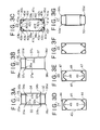
- Figs. 3A to 3G each illustrate a section (corresponding to the section as seen in the arrowed direction A-A in Fig. 1A) in a curvilinear portion of a boom structure.
- a generally rectangular section is formed by a part of an external pipe portion and members welded to the pipe. This section can take various shapes as illustrated in Figs. 3A to 3G.
- a section is formed by two pipes 31 and 32 each having a rectangular section and two flat plate members 33 and 34 (flat plate portions 33 and 34). Ends (33a, 33b, 34a, 34b) of the flat plate members 33 and 34 are welded so as to overlap bent portions (31a, 31b, 32a, 32b) which are different from corners 35a ⁇ d of sections of the pipes 31 and 32.
- a pipe 36 having a rectangular section is disposed on an upper side of a generally rectangular section and a member 37 having a " " -shaped or horseshoe or U-shaped section is welded thereto to form the generally rectangular section.
- upper corners 38a and 38b in this section are formed by the pipe 36.
- lower corners 38c and 38d are formed by the member 37. Ends 37c and 37d of flat plate portions 37a and 37b which form both side faces of the member 37 are welded so as to overlap bent portions 36a and 36b which are different from the corners 38a and 38b in the generally rectangular section of the pipe 36.
- pipes 39 (39a to 39d) each having a triangular section are disposed at four corners respectively of a section of the boom structure.
- the pipes 39 and flat plate members 41 (41a ⁇ d) are welded together to form a generally rectangular section. Corners 40a ⁇ d are formed by the pipes 39. Bent portions 42a ⁇ h different from the corners 40a ⁇ d of the pipes 39 are welded so as to overlap ends 43a ⁇ h of the flat plate members 41.
- each of them is made up of two pipes 44 or 47 disposed up and down and two flat plate members 45 or 48 which constitute both side faces of a generally rectangular section. External portions of the pipes 44 or 47 which portions are positioned inside the generally rectangular section are formed with recesses 46 or 49 which are depressed inwards of the pipes 44 or 47.
- the recesses 46 and 49 are formed in the shapes of an arch and a trapezoid, respectively.
- the recesses 46 or 49 can also improve the strength against bending in the width direction of the boom structure and the strength in a torsional direction of the boom structure.
- a boom structure 26 shown in Fig. 3F corresponds to a modification of the boom structure shown in Fig. 3C, in which the bent portions 42a ⁇ h are formed with stepped portions respectively and ends 43a ⁇ h are welded to the stepped portions.
- the bent portions 42a ⁇ h are formed with stepped portions respectively and ends 43a ⁇ h are welded to the stepped portions.
- a boom structure 27 shown in Fig. 3G corresponds to a modification of the boom structure shown in Fig. 3A, in which the corners 35a ⁇ d are formed with slant portions.
- the sectional shape is not always limited to one having right-angled corners, but there also may be adopted such a shape as the corners being formed with slant or round portions.
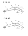
- Figs. 4A and 4B there are illustrated modifications related to pipe positions disposed in the longitudinal direction of the boom.
- pipes 51 (51a, 51b) or 52 (52a, 52b) are disposed up and down of a generally rectangular section. Portions common to Figs. 1A and 1B are denoted by the same reference numerals.
- a pipe 51a disposed on the upper side of the section extends over an area from a curvilinear portion 2b to a second straight portion 2c.
- a pipe 51b disposed on the lower side of the section extends from the curvilinear portion 2b to a first straight portion 2a.
- An arm cylinder for actuating an arm is disposed above the generally rectangular section at a position between the curvilinear portion 2b and the arm mounted on a front end side of the boom, while boom cylinders for actuating the boom are disposed below the generally rectangular section at a position between the curvilinear portion 2b and the construction machine body on the boom support side (see Fig. 5).
- the upper and lower pipes 52a and 52b in the section are both disposed in only the curvilinear portion 2b.
- Fig. 6A is a side view of the boom structure 60 and Fig. 6B schematically illustrates a section thereof as seen in the arrowed direction B-B. As to portions overlapping the first embodiment in explanation, explanations thereof will be omitted accordingly.
- the boom structure 60 which is generally rectangular in section (see Fig. 6B), has a first straight portion 61a, a curvilinear portion 61b and a second straight portion 61c in its longitudinal direction and is formed in the shape of " ⁇ .”
- the boom structure 60 is further provided with an arm connector 63, a bracket 64, a boss portion 65 and a body connector 66.
- Members 67 are arranged so as to give a generally rectangular section (as seen in the arrowed direction B-B).
- members corresponding to all of the members 67 in the boom structure 60 which form four upper and lower corners 68 (68a ⁇ d) of the section
- L-shaped members 67 (67a ⁇ d) having a generally L-shaped section.
- the members 67a ⁇ d are welded together by butt welding to form the section. That is, the corners 68 are formed by bent portions of the L-shaped members 67. Ends of the L-shaped members 67 which extend in the longitudinal direction of the boom are welded together by butt welding to form welded portions 69 (69a ⁇ d).
- the reinforcing members 70 are disposed inside the section.
- the reinforcing members 70 are bridgewise mounted so as to form closed sections conjointly with the corners 68. That is, the reinforcing members 70 are provided in an opposed relation to the corners 68 and both ends of each reinforcing member 70 extending in the longitudinal direction of the boom are welded to the inside of the section.
- the reinforcing members 70 are arranged up and down of the generally rectangular section throughout all of the first straight portion 61a, curvilinear portion 61b and second straight portion 61c in the longitudinal direction of the boom. In at least the curvilinear portion 61b in the longitudinal direction of the boom, the reinforcing members 70 are bridgewise mounted so as to form closed sections conjointly with the corners 68 located at least one of upper and lower sides of the section.
- the four corners are formed by the bent portions of the members arranged therein, so that the butt-welded portions of the members which constitute the section can be positioned away from the corners, whereby it is possible to ensure a required strength of the base metal at the corners which undergo a high stress.
- reinforcing members so as to form closed sections in at least one of the upper and lower corners of the section. Therefore, it is possible to increase the second moment of area of the boom structure 60 and improve the fatigue strength.
- the fatigue strength of the corners 68 is thus improved, so, by using the L-shaped members 67 which are thin-walled, it is possible to make the total weight of the boom member lighter than in the prior art and ensure a fatigue strength equal to or higher than that in the prior art. That is, in comparison with thickening the boom-constituting plates for reinforcement or using partition walls or the like, it is possible to ensure a sufficient fatigue strength with less material and attain the reduction of weight.
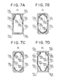
- Figs. 7A ⁇ 9C are each illustrated by a section (corresponding to the section as seen in the arrowed direction B-B in Fig. 6A) in a curvilinear portion of a boom structure.
- a reinforcing member is bridgewise mounted so as to form a closed section conjointly with a corner in a generally rectangular section.
- each corner of a generally rectangular section is formed using an L-shaped member as one of boom members.
- the section is formed by four L-shaped members 72 (72a ⁇ d). Since each corner is formed by a bent portion of an L-shaped member, butt-welded portions of the L-shaped member can be positioned away from the corner and hence a required strength of the base metal can be ensured at each corner which undergoes a high stress.
- reinforcing members 74 At only positions opposed to upper corners 73a and 73b out of corners 73 (73a ⁇ d), there are bridgewise mounted reinforcing members 74 (74a, b) to form closed sections conjointly with the upper corners. Thus, particularly when the strength of the upper corners in the section comes into question, reinforcing members may be disposed preferentially at positions close to the upper corners. By thus arranging reinforcing members efficiently, it is possible to attain both improvement of fatigue strength and reduction of weight at a time.
- reinforcing members 79 (79a ⁇ d) or 80 (80a ⁇ d) are disposed in an opposed relation to four corners of a generally rectangular section which is formed by L-shaped members 77 (77a ⁇ d) or 78 (78a ⁇ d).
- reinforcing members 79 each having an arcuate section.
- reinforcing members 80 each having stepped portions formed at both ends thereof extending longitudinally of the boom.
- L-shaped members 83 (83a ⁇ d) as members which form corners 82 (82a ⁇ d), and, at positions opposed to the corners 82, there are bridgewise mounted flat plate-like reinforcing members 84 (84a ⁇ d).
- side plates 85 85a, b which are thinner than the members 83.
- members having a generally -shaped section are used as corner-forming members out of plural members which define a generally rectangular section.
- the section is formed by butt welding of -shaped members 87 (87a, b).
- 89a ⁇ d At positions opposed to corners 89 (89a ⁇ d), there are bridgewise mounted reinforcing members 88 (88a ⁇ d) so as to form closed sections conjointly with the corners 89.
- a generally rectangular section is formed by butt welding of -shaped members 92 (92a, b) or 93 (93a, b). Since corners of the generally rectangular section are formed by bent portions of the -shaped members, the butt-welded portions of the same members can be located at positions away from the corners, so that a required strength of the base metal can be ensured at corners which undergo a high stress.
- corner reinforcing members 94 (94a, b) for reinforcing the corners are disposed at only positions opposed to upper corners.
- reinforcing members 95 (95a ⁇ d) having an arcuate section are used as members for reinforcing four corners.
- there may be used reinforcing members having stepped portions.
- -shaped members 97 (97a, b) are arranged at upper and lower positions, respectively, of a section of the boom structure. Reinforcing members 98 (98a ⁇ d) are bridgewise mounted at positions opposed to corners of the section. Between the members 97 ( -shaped members 97a and 97b), there are disposed side plates 99 (99a, 99b) which are thinner than the members 96.
- reinforcing members which are bridgewise mounted so as to form closed sections together with corners of a generally rectangular section are disposed outside the section.
- the illustrated section is constituted by four L-shaped sections 121 (121a ⁇ d) having a generally L-shaped section. Bent portions which form four corners 122 (122a ⁇ d) are bent in two steps to form slant portions. Reinforcing members 123 (123a ⁇ d) having an L-shaped section are bridgewise mounted outside the section so as to form closed sections together with the corners 122.
- a boom structure 124 shown in Fig. 9B corners of a generally rectangular section are formed by L-shaped members 125 (125a ⁇ d) each having a slant portion as in the boom structure 120. Reinforcing members 126 (126a ⁇ d) having an L-shaped section are disposed outside the corners. Between the members 125 (between the L-shaped members 125a and 125c and also between the L-shaped members 125b and 125d), there are disposed side plates 127 (127a, b) which are thinner than the members 125.
- L-shaped members 129 (129a, b) each having a slant portion and reinforcing members 130 (130a, b) of an L-shaped section positioned outside with respect to corners formed by the members 129.
- a -shaped member 131 On the lower side of the section, there is disposed a -shaped member 131 having a -shaped section. Since the corners are reinforced from the outside, it is possible to increase the second (or secondary) moment of area and improve the fatigue strength.
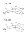
- FIGs. 10A and 10B modifications related to installed positions of reinforcing members in the boom longitudinal direction are illustrated in Figs. 10A and 10B.
- Boom structures 132 and 133 whose side faces are shown in both figures are each provided with reinforcing members 134 (134a, b) or 135 (135a, b) on upper and lower sides of a generally rectangular section.
- Portions common to the boom structure 60 shown in Fig. 6 are denoted by the same reference numerals.
- a reinforcing member 134a disposed on the upper side of a generally rectangular section extends from a curvilinear portion 61b to a second straight portion 61c.
- a reinforcing member 134b disposed on the lower side of the same section extends from the curvilinear portion 61b to a first straight portion 61a.
- the reinforcing members 134 can be disposed efficiently at the portions where a high stress is developed.
- upper and lower reinforcing members 135a and 135b in a generally rectangular section are disposed in only a curvilinear portion 61b.
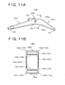
- Fig. 11A is a side view of the boom structure 136 and Fig. 11B is a sectional view thereof as seen in the arrowed direction C-C in Fig. 11A.
- Fig. 11B is a sectional view thereof as seen in the arrowed direction C-C in Fig. 11A.
- the boom structure 136 which has a generally rectangular section (see Fig. 11B), comprises a first straight portion 137a, a curvilinear portion 137b and a second straight portion 137c in its longitudinal direction and is formed in the shape of " ⁇ .”
- the boom structure 136 is further provided with an arm connector 138, a bracket 139, a boss portion 140, and a body connector 141.
- the generally rectangular section (as seen in the arrowed direction C-C in Fig. 11A) is formed by members 142 (142a, b) and 143 (143a, b), as shown in Fig. 11B.
- members 142 and 143 Out of the members 142 and 143, as to members which form corners 144 (144a ⁇ d) of the section, there are used -shaped members having a generally -shaped section.
- side plates 143 members 143 which are thinner than the members 142.
- These members (142, 143) are butt-welded to form the section.
- the corners 144 are formed by bent portions of the -shaped members.
- each reinforcing member 145 is bridgewise mounted so as to form a closed section conjointly with two corners (144a and 144b, or 144c and 144d) in this section. More specifically, reinforcing members 145a and 145b are bridgewise mounted substantially in parallel with an upper surface 146a and a lower surface 146b in the section, and both ends of each of the reinforcing members 145 extending in the longitudinal direction of the boom are welded to the inside of the section. As indicated with dotted lines in Fig.
- the reinforcing members 145 are disposed respectively on the upper and lower sides of the section throughout all of the first straight portion 137a, curvilinear portion 137b and second straight portion 137c in the longitudinal direction of the boom.
- a reinforcing member 145 in at least the curvilinear portion 137b, is provided a reinforcing member 145 so as to form a closed section conjointly with at least one of upper and lower corners 144 in the section.
- the boom structure 136 like the boom structure of the second embodiment, a required strength of the base metal can be ensured at the corners which undergo a high stress, and in the curvilinear portion is disposed a reinforcing member so as to form a closed section for at least one of upper and lower corners in the generally rectangular section. Consequently, it is possible to increase the second moment of area of the boom structure 136 and improve the fatigue strength. Besides, with the reinforcing members bridgewise mounted opposedly to the upper and lower surfaces in the section, it is possible to efficiently suppress an inwardly defecting sectional deformation of both side plates in an excavating work and improve the fatigue strength.
- the fatigue strength of the corners 144 is thus improved, so, by using the members 142 and 143 which are thin-walled, it is possible to make the total weight of the boom member lighter than in the prior art and ensure a fatigue strength equal to or higher than that in the prior art. That is, as compared with thickening the boom-constituting plates or using partition walls, it is possible to ensure a sufficient fatigue strength with less material and attain the reduction of weight.
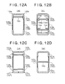
- Figs. 12A to 12D are each represented by a section (corresponding to the section as seen in the arrowed direction C-C in Fig. 11A) in a curvilinear portion of a boom structure.
- a reinforcing member is bridgewise mounted so as to form a closed section conjointly with two corners.
- a generally rectangular section is formed by -shaped members 147 (147a, b) and side plates 148 (148a, b).
- a reinforcing member 150 On only the upper side of this section there bridgewise is mounted a reinforcing member 150 so as to form a closed section together with two corners (149a, 149b).
- a generally rectangular section is formed by -shaped members 152 (152a, b) and side plates 153 (153a, b).
- Reinforcing members 154 (154a, b) each forming a closed section conjointly with two corners are bridgewise mounted at upper and lower positions, respectively, in the section. Both ends of each reinforcing member 154 extending in the longitudinal direction of the boom are formed with bent portions 155, whereby it is possible to increase the second moment of area of the reinforcing members 154 and improve the fatigue strength of the boom.
- L-shaped members 158 (158a ⁇ d) having an L-shaped section are used as members for forming corners 157 (157a ⁇ d). More specifically, bent portions of the members 158 form the corners 157, and flat plate-like reinforcing members 159 (159a, b) are each mounted bridgewise between two L-shaped members (158a and 158b, or 158c and 158d).
- a generally rectangular section is formed by -shaped members 161 (161a, b) and side plates 162 (162a, b), and a reinforcing member 163 is bridgewise mounted between both side plates (162a and 162b). Also with the reinforcing plate 163, it is possible to increase the second moment of area of the boom structure and improve the fatigue strength.
- the member 37 shown in Fig. 3B may be substituted by a member obtained by butt-welding the L-shaped members 72c and 72d shown in Fig. 7A. combination of Figs. 7B and 7C is also applicable.
- the boom structure according to the present invention which is used in a construction machine and has a generally rectangular section, is characterized in that it comprises a first straight portion, a curvilinear portion contiguous to the first straight portion, and a second straight portion contiguous to the curvilinear portion, in its longitudinal direction, and that, in at least the curvilinear portion in the longitudinal direction of the boom, corners positioned on at least one of the upper and lower sides of the generally rectangular section are formed using a pipe which has a closed section.
- the boom structure according to the present invention which is used in a construction machine and has a generally rectangular section, is characterized in that it comprises a first straight portion, a curvilinear portion contiguous to the first straight portion, and a second straight portion contiguous to the curvilinear portion, in its longitudinal direction, that the generally rectangular section is formed substantially by butt welding of plural members and the four corners thereof are formed by bent portions of the members, and that, in at least the curvilinear portion in the longitudinal direction of the boom, there is provided a reinforcing member so as to form a closed section conjointly with corners positioned on at least one of the upper and lower sides of the generally rectangular section.
- the butt-welded portions of the members can be positioned away from the corners. Consequently, it is possible to ensure a required strength of the base metal at the corners which undergo a high stress. Since, in the curvilinear portion wherein fatigue strength comes into question, there is disposed a reinforcing member so as to form a closed section together with corners, it is possible to increase the second moment of area of the boom structure and improve the fatigue strength. Thus, in comparison with thickening the boom-constituting plates or using partition walls or the like, it is possible to ensure a sufficient fatigue strength with less material and attain the reduction of weight.
Landscapes
- Engineering & Computer Science (AREA)
- Mechanical Engineering (AREA)
- Mining & Mineral Resources (AREA)
- Civil Engineering (AREA)
- General Engineering & Computer Science (AREA)
- Structural Engineering (AREA)
- Body Structure For Vehicles (AREA)
- Forklifts And Lifting Vehicles (AREA)
- Excavating Of Shafts Or Tunnels (AREA)
Abstract
Description


Claims (20)
- A boom structure of a construction machine, comprising:a boom having a curvilinear portion bending in a longitudinal direction of said boom, wherein a tubular member which forms one or more of corners of a generally rectangular section in said curvilinear portion, said tubular member having a closed section.
- The boom structure according to claim 1, wherein said curvilinear portion is positioned contiguously between a first and a second straight portion in the longitudinal direction of the boom.
- The boom structure according to claim 1, wherein said tubular member has a flat portion extending in the longitudinal direction of the boom.
- The boom structure according to claim 1, wherein said generally rectangular section is formed by a part of an outline of said tubular member and a welded member welded to said tubular member, said welded member having a flat plate portion extending in the longitudinal direction of the boom, ends of said flat plate portion being welded to bent portions of said tubular member other than said corners.
- The boom structure according to claim 1, wherein said tubular member is disposed on each of upper and lower sides of said generally rectangular section so that the tubular member forms two of said corners.
- The boom structure according to claim 5, wherein a recess depressed inwards of said tubular member is formed inside of said generally rectangular section.
- The boom structure according to claim 1, wherein said tubular member is disposed at each of the corners of said generally rectangular section so that the tubular member constitutes each of said corners respectively.
- The boom structure according to claim 4, wherein each stepped portion depressed inwards of said tubular member is formed in said bent portions and said ends of said flat plate portion are welded to said each stepped portion.
- The boom structure according to claim 2, wherein said first straight portion is positioned on a front end side of the boom to which an arm is attached, said second straight portion is positioned on a support side of the boom which is supported by a construction machine body, and said tubular member comprises a first tubular member disposed on an upper side of said generally rectangular section and extending from said curvilinear portion to said second straight portion and a second tubular member disposed on a lower side of said generally rectangular section and extending from said curvilinear portion to said first straight portion.
- The boom structure according to claim 1, wherein said tubular member is one of a seamless steel pipe and an electroseamed steel pipe.
- A boom structure of a construction machine, comprising:a boom having a hollow section, said boom having a curvilinear portion bending in a longitudinal direction of said boom and being formed by welding of plural boom members, corners of a generally rectangular section in said curvilinear portion being formed by bent portions of said boom members; anda reinforcing member which is fixed to each of said boom members so as to form a closed section conjointly with one or more of said corners of said generally rectangular section.
- The boom structure according to claim 11, wherein said curvilinear portion is positioned contiguously between a first and a second straight portion in the longitudinal direction of said boom.
- The boom structure according to claim 11, wherein said boom members which form said corners of said generally rectangular section are L-shaped members having a generally L-shaped section.
- The boom structure according to claim 11, wherein said boom members which form said corners of said generally rectangular section are horseshoe members having a generally horseshoe section.
- The boom structure according to claim 11, wherein said reinforcing member is mounted so as to form a closed section conjointly with one of said corners.
- The boom structure according to claim 11, wherein said reinforcing member is disposed inside said generally rectangular section.
- The boom structure according to claim 11, wherein said reinforcing member is disposed outside said generally rectangular section.
- The boom structure according to claim 11, wherein said reinforcing member is mounted so as to form a closed section conjointly with two of said corners.
- The boom structure according to claim 11, further comprising:side plate disposed between said boom members which form said corners, said side plate being thinner than each of said boom members.
- A method for manufacturing a boom structure of a construction machine, comprising the steps of:wherein said bent portion of said deformed pipe is positioned at corners of said generally rectangular section, and said boom structure has, in its longitudinal direction, a first straight portion to which an arm is attached, a curvilinear portion contiguous to said first straight portion and including said bent portion of said deformed pipe, and a second straight portion contiguous to said curvilinear portion and supported by a construction machine body.passing a circular pipe through profile rolls to form a deformed pipe;forming a bent portion in a longitudinal direction of said deformed pipe at the time of forming the deformed pipe; andwelding a member having a flat plate portion to said deformed pipe to form a boom structure having a generally rectangular section,
Applications Claiming Priority (4)
| Application Number | Priority Date | Filing Date | Title |
|---|---|---|---|
| JP2002226256 | 2002-08-02 | ||
| JP2002226256 | 2002-08-02 | ||
| JP2002262198 | 2002-09-09 | ||
| JP2002262198A JP2004124357A (en) | 2002-08-02 | 2002-09-09 | Boom structure and manufacturing method of boom member |
Publications (2)
| Publication Number | Publication Date |
|---|---|
| EP1387012A2 true EP1387012A2 (en) | 2004-02-04 |
| EP1387012A3 EP1387012A3 (en) | 2004-04-07 |
Family
ID=30117513
Family Applications (1)
| Application Number | Title | Priority Date | Filing Date |
|---|---|---|---|
| EP03254641A Withdrawn EP1387012A3 (en) | 2002-08-02 | 2003-07-23 | Boom structure of construction machine and manufacturing method |
Country Status (4)
| Country | Link |
|---|---|
| US (1) | US20040161326A1 (en) |
| EP (1) | EP1387012A3 (en) |
| JP (1) | JP2004124357A (en) |
| CN (1) | CN1480596A (en) |
Cited By (10)
| Publication number | Priority date | Publication date | Assignee | Title |
|---|---|---|---|---|
| WO2007041739A1 (en) * | 2005-10-12 | 2007-04-19 | Palfinger Ag | Crane with reinforcing plate |
| EP2141289A4 (en) * | 2007-04-25 | 2011-04-27 | Komatsu Mfg Co Ltd | Work machine boom |
| EP2548834A1 (en) * | 2011-07-21 | 2013-01-23 | Manitowoc Crane Companies, LLC | Tailor welded panel beam for construction machine and method of manufacturing |
| JP2015098717A (en) * | 2013-11-19 | 2015-05-28 | キャタピラー エス エー アール エル | Construction machinery boom |
| EP3553231A1 (en) * | 2018-04-11 | 2019-10-16 | Deere & Company | Hybrid loader boom arm assembly |
| US10662609B2 (en) | 2018-04-11 | 2020-05-26 | Deere & Company | Hybrid loader boom arm assembly |
| US10697148B2 (en) | 2018-04-11 | 2020-06-30 | Deere & Company | Hybrid loader boom arm assembly |
| US10822768B2 (en) | 2018-04-11 | 2020-11-03 | Deere & Company | Hybrid loader boom arm assembly |
| WO2022180160A1 (en) * | 2021-02-26 | 2022-09-01 | Putzmeister Engineering Gmbh | Boom-arm segment and method for producing a boom-arm segment |
| EP4119743A4 (en) * | 2020-03-10 | 2024-04-17 | Sany Automobile Manufacturing Co., Ltd. | BOOM AND WORK EQUIPMENT |
Families Citing this family (17)
| Publication number | Priority date | Publication date | Assignee | Title |
|---|---|---|---|---|
| WO2005001211A1 (en) * | 2003-06-30 | 2005-01-06 | Hitachi Construction Machinery Co., Ltd. | Working arm for construction machine and method of producing the same |
| JP4170962B2 (en) * | 2004-07-22 | 2008-10-22 | 日立建機株式会社 | Front device |
| JP4641800B2 (en) * | 2005-01-05 | 2011-03-02 | 株式会社クボタ | boom |
| USD534552S1 (en) * | 2005-06-30 | 2007-01-02 | Komatsu Ltd. | Hydraulic excavator |
| US8584362B2 (en) * | 2008-11-06 | 2013-11-19 | Wayne Industrial Holdings, Llc | Three piece lift arm apparatus and method |
| JP5470576B2 (en) * | 2009-06-23 | 2014-04-16 | 株式会社神戸製鋼所 | Hydraulic excavator attachment |
| BR112012007880B1 (en) * | 2009-08-25 | 2020-10-27 | Sumitomo Pipe & Tube Co., Ltd., | manufacturing apparatus for a bent member, method for manufacturing a bent member and bent member |
| CN103189574B (en) * | 2010-11-15 | 2015-06-10 | 日立建机株式会社 | Construction machine swing frame |
| ITMI20120206A1 (en) * | 2012-02-14 | 2013-08-15 | Cifa Spa | SEGMENT OF AN ARTICULATED ARM AND ARTICULATED ARM INCLUDING THE SEGMENT |
| JP5937626B2 (en) * | 2012-02-16 | 2016-06-22 | 日立建機株式会社 | Construction machine arm |
| CN105584943A (en) * | 2016-01-15 | 2016-05-18 | 三一帕尔菲格特种车辆装备有限公司 | Crane boom and crane |
| CN105804134A (en) * | 2016-05-12 | 2016-07-27 | 华若延 | Cantilever structure of construction machine and manufacturing method for cantilever structure |
| JP6998148B2 (en) * | 2017-08-04 | 2022-01-18 | 株式会社竹内製作所 | Cylindrical structure and work equipment |
| DE102017223240A1 (en) * | 2017-12-19 | 2019-06-19 | Putzmeister Engineering Gmbh | Concrete pump mast arm segment with longitudinally variable plate thickness and method of making such a concrete pump mast arm segment |
| CN109930639B (en) * | 2019-04-16 | 2024-02-13 | 徐州徐工矿业机械有限公司 | Excavator movable arm and excavator |
| CN111335638A (en) * | 2020-03-10 | 2020-06-26 | 三一汽车制造有限公司 | Booms and work equipment |
| DE202023101065U1 (en) * | 2023-03-07 | 2024-06-10 | Liebherr-Mischtechnik Gmbh | Distributor boom arm |
Family Cites Families (11)
| Publication number | Priority date | Publication date | Assignee | Title |
|---|---|---|---|---|
| US1917666A (en) * | 1931-02-21 | 1933-07-11 | Koehring Co | Welded dipper stick construction |
| DE1634979B2 (en) * | 1963-12-18 | 1973-08-30 | HANGING DEVICE FOR AN EXCAVATOR TO A CARRIER VEHICLE | |
| DE2317595A1 (en) * | 1973-04-07 | 1974-10-31 | Kaspar Klaus | TELESCOPIC UNIT, IN PARTICULAR FOR LIFTING EQUIPMENT |
| US4214923A (en) * | 1978-10-04 | 1980-07-29 | Caterpillar Tractor Co. | Method for treating metal |
| FR2445481A1 (en) * | 1978-12-29 | 1980-07-25 | Poclain Sa | MECHANICAL WELDED STRUCTURE OF A FORCE ARM |
| JPS5711731A (en) * | 1980-06-25 | 1982-01-21 | Komatsu Ltd | Production of curved boom |
| JP3501876B2 (en) * | 1995-07-04 | 2004-03-02 | ヤンマー株式会社 | Backhoe working arm structure |
| JPH09165773A (en) * | 1995-12-15 | 1997-06-24 | Komatsu Ltd | Hydraulic excavator working machine |
| JP3794004B2 (en) * | 1998-03-04 | 2006-07-05 | 株式会社小松製作所 | Construction machine working machine |
| JP2000199240A (en) * | 1998-12-28 | 2000-07-18 | Yutani Heavy Ind Ltd | Hydraulic excavator boom structure |
| JP2001081810A (en) * | 1999-09-13 | 2001-03-27 | Kubota Corp | Work equipment boom |
-
2002
- 2002-09-09 JP JP2002262198A patent/JP2004124357A/en active Pending
-
2003
- 2003-07-22 US US10/623,555 patent/US20040161326A1/en not_active Abandoned
- 2003-07-23 EP EP03254641A patent/EP1387012A3/en not_active Withdrawn
- 2003-08-01 CN CNA031525326A patent/CN1480596A/en active Pending
Cited By (14)
| Publication number | Priority date | Publication date | Assignee | Title |
|---|---|---|---|---|
| WO2007041739A1 (en) * | 2005-10-12 | 2007-04-19 | Palfinger Ag | Crane with reinforcing plate |
| EP2141289A4 (en) * | 2007-04-25 | 2011-04-27 | Komatsu Mfg Co Ltd | Work machine boom |
| US8297906B2 (en) | 2007-04-25 | 2012-10-30 | Komatsu Ltd. | Work equipment boom |
| US9290363B2 (en) | 2011-07-21 | 2016-03-22 | Manitowoc Crane Companies, Llc | Tailor welded panel beam for construction machine and method of manufacturing |
| EP2865632A1 (en) * | 2011-07-21 | 2015-04-29 | Manitowoc Crane Companies, LLC | Tailor welded panel beam for construction machine and method of manufacturing |
| EP2548834A1 (en) * | 2011-07-21 | 2013-01-23 | Manitowoc Crane Companies, LLC | Tailor welded panel beam for construction machine and method of manufacturing |
| JP2015098717A (en) * | 2013-11-19 | 2015-05-28 | キャタピラー エス エー アール エル | Construction machinery boom |
| EP3553231A1 (en) * | 2018-04-11 | 2019-10-16 | Deere & Company | Hybrid loader boom arm assembly |
| US10662609B2 (en) | 2018-04-11 | 2020-05-26 | Deere & Company | Hybrid loader boom arm assembly |
| US10697148B2 (en) | 2018-04-11 | 2020-06-30 | Deere & Company | Hybrid loader boom arm assembly |
| US10822768B2 (en) | 2018-04-11 | 2020-11-03 | Deere & Company | Hybrid loader boom arm assembly |
| EP4119743A4 (en) * | 2020-03-10 | 2024-04-17 | Sany Automobile Manufacturing Co., Ltd. | BOOM AND WORK EQUIPMENT |
| US12595670B2 (en) | 2020-03-10 | 2026-04-07 | Sany Automobile Manufacturing Co., Ltd. | Boom and working equipment |
| WO2022180160A1 (en) * | 2021-02-26 | 2022-09-01 | Putzmeister Engineering Gmbh | Boom-arm segment and method for producing a boom-arm segment |
Also Published As
| Publication number | Publication date |
|---|---|
| EP1387012A3 (en) | 2004-04-07 |
| CN1480596A (en) | 2004-03-10 |
| JP2004124357A (en) | 2004-04-22 |
| US20040161326A1 (en) | 2004-08-19 |
Similar Documents
| Publication | Publication Date | Title |
|---|---|---|
| US20040161326A1 (en) | Boom structure of construction machine and manufacturing method thereof | |
| EP2700752A1 (en) | Boom for construction machine | |
| CN101356321B (en) | boom | |
| US6508019B1 (en) | Boom of bucket type excavator and method for making same | |
| JP3866756B2 (en) | Working arm for construction machine and method for manufacturing the same | |
| US20140334906A1 (en) | Arm for construction machine | |
| EP2711466B1 (en) | Arm for construction machinery | |
| US20020056212A1 (en) | Structure for working unit for bucket excavators and method for manufacturing the same | |
| JPWO1999004104A1 (en) | Bucket excavator work equipment structure and manufacturing method thereof | |
| JPWO2008047505A1 (en) | Pipe reinforcement structure and construction machine cab structure including the same | |
| JP2005029984A (en) | Working arm for construction machine and manufacturing method thereof | |
| JP2001342646A (en) | Turning frame of construction machine | |
| JP3836683B2 (en) | Working arm structure of work machine | |
| JPH09165773A (en) | Hydraulic excavator working machine | |
| US20060182597A1 (en) | Boom assembly | |
| JPH10121505A (en) | Hydraulic excavator working machine | |
| JP2000265489A (en) | Work arm structure of work machine | |
| JPH1110383A (en) | Welding member and method for forming welded portion | |
| JPH11158907A (en) | Work machine boom structure | |
| JPH11140901A (en) | Hydraulic excavator work equipment arm | |
| JP2000248575A (en) | Work arm structure of work machine | |
| CN212801728U (en) | Reinforced excavator bucket | |
| JP2026077972A (en) | Boom for work machine, work machine, and method for manufacturing a boom for work machine | |
| JP2004092210A (en) | Work machine | |
| KR100922771B1 (en) | Long structural member of working machine |
Legal Events
| Date | Code | Title | Description |
|---|---|---|---|
| PUAI | Public reference made under article 153(3) epc to a published international application that has entered the european phase |
Free format text: ORIGINAL CODE: 0009012 |
|
| AK | Designated contracting states |
Kind code of ref document: A2 Designated state(s): AT BE BG CH CY CZ DE DK EE ES FI FR GB GR HU IE IT LI LU MC NL PT RO SE SI SK TR |
|
| AX | Request for extension of the european patent |
Extension state: AL LT LV MK |
|
| PUAL | Search report despatched |
Free format text: ORIGINAL CODE: 0009013 |
|
| AK | Designated contracting states |
Kind code of ref document: A3 Designated state(s): AT BE BG CH CY CZ DE DK EE ES FI FR GB GR HU IE IT LI LU MC NL PT RO SE SI SK TR |
|
| AX | Request for extension of the european patent |
Extension state: AL LT LV MK |
|
| 17P | Request for examination filed |
Effective date: 20040929 |
|
| AKX | Designation fees paid |
Designated state(s): AT BE BG CH CY CZ DE DK EE ES FI FR GB GR HU IE IT LI LU MC NL PT RO SE SI SK TR |
|
| STAA | Information on the status of an ep patent application or granted ep patent |
Free format text: STATUS: THE APPLICATION HAS BEEN WITHDRAWN |
|
| 18W | Application withdrawn |
Effective date: 20060518 |