EP1386996A1 - Machine à laver - Google Patents
Machine à laver Download PDFInfo
- Publication number
- EP1386996A1 EP1386996A1 EP03017272A EP03017272A EP1386996A1 EP 1386996 A1 EP1386996 A1 EP 1386996A1 EP 03017272 A EP03017272 A EP 03017272A EP 03017272 A EP03017272 A EP 03017272A EP 1386996 A1 EP1386996 A1 EP 1386996A1
- Authority
- EP
- European Patent Office
- Prior art keywords
- drum
- washing water
- water circulation
- circulation apparatus
- tub
- Prior art date
- Legal status (The legal status is an assumption and is not a legal conclusion. Google has not performed a legal analysis and makes no representation as to the accuracy of the status listed.)
- Granted
Links
Images


Classifications
-
- B—PERFORMING OPERATIONS; TRANSPORTING
- B05—SPRAYING OR ATOMISING IN GENERAL; APPLYING FLUENT MATERIALS TO SURFACES, IN GENERAL
- B05B—SPRAYING APPARATUS; ATOMISING APPARATUS; NOZZLES
- B05B1/00—Nozzles, spray heads or other outlets, with or without auxiliary devices such as valves, heating means
- B05B1/26—Nozzles, spray heads or other outlets, with or without auxiliary devices such as valves, heating means with means for mechanically breaking-up or deflecting the jet after discharge, e.g. with fixed deflectors; Breaking-up the discharged liquid or other fluent material by impinging jets
- B05B1/262—Nozzles, spray heads or other outlets, with or without auxiliary devices such as valves, heating means with means for mechanically breaking-up or deflecting the jet after discharge, e.g. with fixed deflectors; Breaking-up the discharged liquid or other fluent material by impinging jets with fixed deflectors
- B05B1/267—Nozzles, spray heads or other outlets, with or without auxiliary devices such as valves, heating means with means for mechanically breaking-up or deflecting the jet after discharge, e.g. with fixed deflectors; Breaking-up the discharged liquid or other fluent material by impinging jets with fixed deflectors the liquid or other fluent material being deflected in determined directions
-
- D—TEXTILES; PAPER
- D06—TREATMENT OF TEXTILES OR THE LIKE; LAUNDERING; FLEXIBLE MATERIALS NOT OTHERWISE PROVIDED FOR
- D06F—LAUNDERING, DRYING, IRONING, PRESSING OR FOLDING TEXTILE ARTICLES
- D06F39/00—Details of washing machines not specific to a single type of machines covered by groups D06F9/00 - D06F27/00
- D06F39/08—Liquid supply or discharge arrangements
- D06F39/083—Liquid discharge or recirculation arrangements
-
- D—TEXTILES; PAPER
- D06—TREATMENT OF TEXTILES OR THE LIKE; LAUNDERING; FLEXIBLE MATERIALS NOT OTHERWISE PROVIDED FOR
- D06F—LAUNDERING, DRYING, IRONING, PRESSING OR FOLDING TEXTILE ARTICLES
- D06F37/00—Details specific to washing machines covered by groups D06F21/00 - D06F25/00
- D06F37/42—Safety arrangements, e.g. for stopping rotation of the receptacle upon opening of the casing door
Definitions
- the present invention relates to a washing machine, and more particularly, to a washing machine having an improved circulation apparatus for pumping water in a lower side of the tub and discharging the pumped water from an upper side of the tub.
- a washing machine is an apparatus for eliminating contaminants from laundry by the interaction of detergent and water.
- Washing machines are generally classified into agitator type, pulsator type, and drum type washing machines.
- the agitator type washing machine washes laundry by rotating a washing rod overtopping at the center of the washing tub in left and right directions.
- the pulsator type washing machine washes laundry using the frictional force generated between water current and laundry by rotating the disk-shaped pulsator in right and left directions.
- the drum type washing machine washes laundry by loading water, detergent and laundry into a drum with a plurality of protruded tumbling ribs installed in an inner surface of the drum and rotating the drum at a low speed.
- auxiliary units are additively provided, such as a washing water circulation apparatus, for example.
- the washing water circulation apparatus allows objects to be washed received in the drum or washing tub to be wet rapidly, and enhances the washing efficiency by increasing the frictional force due to water current.
- the washing water circulation apparatus is configured to pump water in an inner lower space of the tub and discharge the pumped water from the upper side to the inner space of the drum or washing tub.
- the washing water circulation apparatus has a plurality of small injection holes for injecting the pumped water into the inner space of the drum or the washing tub.
- the water in the tub contains a considerable amount of foreign particles such as lint. Therefore, the foreign particles are pumped along with the water in the tub through the washing water circulation apparatus and then injected through the injection holes. Over a long period of time, the injection holes are choked with the foreign particles, causing problems in the washing machine.
- the water that is pumped through the washing water circulation apparatus is generally injected only in one direction, the pumped water cannot be uniformly injected into the washing objects received in the drum or washing tub.
- the present invention is directed to a washing machine that substantially obviates one or more problems due to limitations and disadvantages of the related art.
- An advantage of the present invention is to provide an improved washing water circulation apparatus in which clogging due to lint is prevented.
- Another advantage of the present invention is to provide an improved washing water circulation apparatus in which water is injected in various directions.
- a washing water circulation apparatus including a circulation motor, a circulation hose and an injection unit.
- the circulation motor communicates with a lower side of a tub of a washing machine to pump water in the tub.
- the circulation hose has one end that is connected with the circulation motor, and guides the pumped water.
- the injection unit includes a cylindrical connector and a nozzle.
- the cylindrical connector is installed between a door and the tub and provided so as to penetrate a gasket for preventing water leakage.
- One end of the cylindrical connector is connected with the circulation hose.
- the nozzle is provided below the gasket.
- the nozzle has a facing surface facing an inside of a drum and left and right surfaces of the facing surface, the facing surface and the left and right surfaces being completely opened.
- the nozzle disperses the water, which is discharged to a lower side from the cylinder, into the inside of the drum to inject the dispersed water.
- the present invention is not limited to cylindrical connectors, rather the connectors can have a variety of cross-sectional shapes, such as a square or triangle.
- the washing water circulation apparatus of the present invention may be configured to further include an annular rib extending from one side surface of the gasket so as to hold and support an outer surface of the connector.
- the connector may further include a projection protruded from an outer circumference of the connector for preventing the connector from dropping under the gasket.
- the injection unit may be comprised of a single body.
- the nozzle includes: an upper horizontal part extending from the other end toward the drum; a vertical part extending from an opposite side to a side facing the drum to a lower side; and a lower horizontal part extending from a lower end toward the drum.
- the upper horizontal part has an upper surface, which is supported close to the gasket.
- the vertical part has a center portion that is formed convex toward the drum.
- the lower horizontal part has a center portion, which is formed convex upward.
- the lower horizontal part comprises a guide groove formed in left and right directions.
- the lower horizontal part has an upper surface inclined downward as it travels from the guide groove toward the drum.
- the connector and the nozzle of the injection unit are formed separately from each other.
- the connector is formed of an independent single body, and the nozzle is formed extending from the gasket.
- the nozzle comprises: a vertical part extending downward from a lower surface of the gasket; and a lower horizontal part extending from a lower end of the vertical part toward the drum.
- the vertical part has a center portion, which is formed convex toward the drum.
- the lower horizontal part has a center portion, which is formed convex upward.
- the lower horizontal part comprises a guide groove, which is formed in left and right directions.
- the lower horizontal part has an upper surface inclined downward as it travels from the guide groove toward the drum.
- a washing machine provided with the washing water circulation apparatus.
- the washing machine includes: a case; an outer tub provided within the case and storing water therein; an inner tub provided rotatable within the outer tub and having a plurality of holes communicating with an inner space of the outer tub; and the washing water circulation apparatus mentioned above.
- FIG. 1 is a partial cut-away perspective view of a washing machine according to the present invention
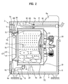
- FIG. 2 is a sectional view of a washing machine according to the present invention.
- FIGs. 1 and 2 illustrate a drum type washing machine in which an outer tub installed in a case and an inner tub installed rotatably in the outer tub are side-opening.
- the present invention is not limited to the illustrated drum type washing machine but can be equally applied to the pulsator type washing machine or a similar machine in which the outer tub and the inner tub are top-opening.
- the outer tub is referred to as 'tub' and the inner tub is referred to as 'drum'.
- a case 2 of the washing machine includes a base 4, a cabinet 6 and a top plate 8.
- the base 4 constitutes the bottom of the case 2. On the base, a damper 4a for supporting a tub 10 to be described later is mounted.
- the cabinet 6 stands on the base 4 so as to form therein a space where the tub 10 can be installed.
- springs 6a holding and supporting the tub 10 are connected.
- a loading hole 7a is formed through which laundry (100) is loaded or unloaded.
- an upper frame 9a and a lower frame 9b are horizontally arranged as shown in FIG. 2.
- the door 40 is installed at a front side of the cabinet 6 so as to open and close the loading hole 7a.
- This door 40 is configured to include a door frame 42 and a door glass 44.
- the door frame 42 is hinge-coupled at the front side of the cabinet and has a hole formed in the center in which the door glass 44 is installed.
- the top plate 8 is mounted on the opened cabinet 6 to seal an inner space formed by the cabinet 6 and the base 4. On a predetermined portion of the top plate 8, a control panel 8a for manipulating the washing machine is equipped.
- the tub 10 is provided in the inner space of the case 2, the tub 10 is provided. As described above, the tub 10 is located at a mid portion of the inner space and supported by the springs 6a and the damper 4a. The tub 10 is installed such that the opened front thereof faces the loading hole 7a of the cabinet 6. In the tub 10 installed as above, water is supplied and stored.
- a drum 20 is rotatably installed in the inner space of the tub 10.
- a motor 28 is installed in the cabinet 6 so as to rotate the drum 20.
- FIG. 2 there is shown an embodiment in which the shaft of the motor 28 is directly coupled to the drum 20. In this case, the shaft penetrates the tub 10.
- the motor 28 may rotate the drum 20 indirectly. In such a case, the drum 20 and the motor 28 can be connected by a belt, for instance.
- a plurality of water holes 21 are formed in the drum 20. Hence, water stored in the tub 10 comes in and out the inner space of the drum 20 through the water holes 21.
- a plurality of tumbling ribs 22 are protruded as shown in FIGs. 1 and 2. The tumbling ribs 22 raise and drop the laundry (100) while the drum 20 is rotated.
- a gasket 30 is installed as shown in FIG. 2.
- the gasket 30 prevents water and laundry (100) received in the drum 20 and the tub 10 from being leaked outside the tub 10 and being introduced into the inner space of the cabinet 6.
- an insertion hole 31 is formed such that an injection unit 70 to be described later is inserted and equipped.
- An annular rib extends from the gasket 30 toward an upward direction of the insertion hole 31.
- a drain 15 is formed.
- a drain bellows tube 51 is connected with the drain 15.
- a pump unit 50 for pumping the water introduced through the drain 15 and the drain bellows tube 51 and draining the pumped water, or circulating the pumped water into the inside of the drum 20 again is connected to the drain bellows tube 51.
- the pump unit 50 is configured to include a pump case 52, a circulation pump 53 and a drain pump 54. Water passing through the drain 15 and the drain bellows tube 51 is introduced into the pump case 2.
- a drain hose 55 communicating with an outside is connected with the drain pump 54.
- the drain pump 54 drains the water introduced into the pump case 52 in the drain process of the washing machine to an outside through the drain hose 55.
- a circulation hose 60 is connected to the circulation pump 53.
- the circulation hose 60 is arranged so that one end is adjacent to the upper side of the gasket 30. Hence, the circulation pump 53 allows the water introduced into the pump case 2 via the circulation hose 60.
- reference numeral 81 indicates a water feed hose for supplying external clean water to the washing machine
- reference numeral 82 indicates a detergent box.
- the detergent box 82 functions to mix the water supplied through the water feed hose 81 with previously stored detergent.
- Reference numeral 83 indicates a feed bellows tube for guiding water discharged from the detergent box 82 to the inside of the tub 10.
- the injection unit 70 is inserted into the insertion hole 31 and a rib 32 of the gasket 30.
- One end of the injection unit 70 is connected with the circulation hose 60 and the other end thereof penetrates the gasket 30 and is located under the gasket 30.
- the injection unit 70 installed as above disperses and discharges the water via the circulation hose 60 into the inner space of the drum 20.
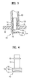
- FIG. 3 is a partial sectional view illustrating an embodiment of a washing water injection unit in a washing machine according to the present invention
- FIG. 4 is a front view of the injection unit of FIG. 3
- FIG. 5 is a perspective view of the injection unit of FIG. 3.
- the injection unit 70 is configured to include a cylindrical connector 72 connected with the circulation hose 60, and a nozzle 74 provided below the gasket 30, for dispersing the water discharged downward from the connector 72 into the inner space of the drum 20 and draining the dispersed water.
- the connector 72 and the nozzle 74 are continuously formed as a single body and equipped in the gasket 30.
- One end of the connector 72 is, as shown in FIG. 3, connected with an end of the circulation hose 60 and the other end thereof is inserted into and equipped in the insertion hole 31 and the rib 32 of the gasket 30.
- the rib 32 holds and stably supports an outer surface of the connector 72.
- an annular projection 73 is protruded as shown in FIG. 3.
- the projection 73 is supported by an upper side of the rib 32.
- the nozzle 74 is provided below the gasket 30. A surface of the nozzle 74 facing the inside of the drum 20 and left and right surfaces thereof are completely opened.
- the nozzle 74 constructed as above disperses water discharged downward from the connector 72 into the inside of the drum 20 through the facing surface and the left and right surfaces of the nozzle 74 and discharges the dispersed water.
- a side where the drum 20 is located is referred to as 'rear side of the nozzle 74' and a side where the door 40 is located is referred to as 'front side of the nozzle 74'.
- the aforementioned nozzle 74 includes an upper horizontal part 75, a vertical part 76, and a lower horizontal part 77.
- the upper horizontal part 75 extends wider at the other end of the connector 72. This upper horizontal part 75, for instance, extends toward the drum 20 and its upper surface is closely contacted with the lower surface of the gasket 30.
- the vertical part 76 extends with a predetermined length downward from the front side of the upper horizontal part, i.e., an opposite side to the side facing the drum 20.
- the lower horizontal part 77 extends toward the rear side, i.e., toward the drum 20 from the lower side of the vertical part.
- the upper horizontal part and the lower horizontal part 77 are arranged parallel to each other with being spaced apart by a predetermined distance from each other.
- the rear side of the nozzle 74 i.e., a direction facing the drum 20 and its left and right directions are all completely opened.
- the vertical part 76 has a center portion, which is formed convex toward the front side, i.e., toward the drum 20 with respect to both sides of the left and right, as shown in FIGs. 3 to 5. If the vertical part 76 is formed as above, it is possible to easily disperse the water, which is dropped downward from the connector 72 and is splashed by the lower horizontal part, in both side directions of the left and right.
- the lower horizontal part 77 has a center portion, which is formed convex upward, i.e., toward the connector 72 with respect to both sides of the left and right. By doing so, it becomes possible to easily disperse the water, which is dropped downward from the connector 72, in both side directions of the lower horizontal part 77.
- a guide groove 78 is formed in the lower horizontal part 77.
- the guide groove 78 is, as shown in FIGs. 3 to 5, provided adjacent to a portion where the lower horizontal part 77 and the vertical part 76 are connected.
- the upper surface of the lower horizontal part 77 is formed inclined downward as it travels from the guide groove 78 to the drum 20. If the lower horizontal part 77 is formed as above, it is possible to easily discharge a part of the water dropped through the connector 72 toward the opened front side of the nozzle 74.
- FIG. 6 is a partial sectional view illustrating another embodiment of a washing water injection unit in a washing machine according to the present invention.
- the connector 72 and the nozzle 74 constituting the injection unit 70 are made in a separate structure.
- the connector 72 is formed in an independent single body structure, and the nozzle 74 is formed extending downward from the gasket 30.
- the connector 72 is formed in a cylindrical shape. On the main outer surface of the connector 72, a projection 73 is formed to prevent the connector 72 from deviating downward from the insertion hole 31 and the rib 32.
- the connector 72 formed as above is installed and equipped penetrating the insertion hole 31 and the rib 32 from the upper side to the lower side of the gasket 30, and one end of the connector 72 is connected with one end of the circulation hose 60.
- the nozzle 74 is configured to include a vertical part 76 and a lower horizontal part.
- the vertical part 76 extends downward from the lower surface of the gasket 30.
- the lower horizontal part 77 extends from the lower end to the rear side of the vertical part, i.e., toward the inside of the drum 20.
- the nozzle 74 in the embodiment shown in FIG. 6 is also shaped to have completely opened rear side and left and right sides like the embodiment described with reference to FIGs. 3 to 5.
- the description related with the shape of the nozzle 74 will be omitted.
- the inventive injection unit 70 shown in FIG. 6 is characterized in that the connector 72 and the nozzle 74 are formed in a separate structure unlike the embodiment described with reference to FIGS. 3 to 5.
- the nozzle 74 is characterized in that it is formed extending from the lower surface of the gasket 30.
- a user opens the door 40 and loads laundry (100) into the inside of the drum 20.
- the door 40 is closed and the washing machine is operated, external water is fed to the detergent box 82 through the water feed hose 81.
- the detergent prepared in advance in the detergent box 82 is dissolved by supplied water, and the water in which detergent is dissolved is fed to the tub through the feed bellows tube 83.
- the drum 20 is rotated by the motor 28.
- the water stored in the tub 10 is naturally introduced into the drum 20 through water holes 21. If the drum 20 is rotated, the laundry (100) is raised by the tumbling ribs 22 and then dropped.
- the laundry (100) is raised by the tumbling ribs 22 and then dropped.
- contaminant is separated from the laundry (100) to perform the washing.
- the circulation pump 53 pumps the water, which was introduced into the pump case 52 through the drain 15 and the drain bellows tube 51 arranged below the tub 10, from the tub 10 to the circulation hose 60.
- the pumped water is introduced into the connector 72 of the injection unit 70 via the circulation hose 60, and is then dropped to the lower horizontal part 77 of the nozzle 74 through the connector 72. At this time, the rear side and the left and right directions of the nozzle 74 are completely opened. Hence, water is uniformly dispersed in the left and right directions and the rear side by guidance of the vertical part 76, guide groove 78 and lower horizontal part 77, and then discharged to the inside of the drum 20.
- the uniformly dispersed and discharged water rapidly wets the laundry (100) received in the drum 20 in an initial stage of the washing process. While the washing is performed, friction and impact energies due to the drop of water are uniformly transferred to the laundry (100) to thereby obtain uniform washing capability.
- the drum 20 and the circulation pump 53 are stopped. After the washing process is completed, the contaminated water is drained to the outside. In the drain process, the drain pump 54 is operated and the water in the tub 10 is discharged to the outside through the drain hose 55.
- the drain pump 54 is stopped, new water is fed to the inside of the tub 10 and the drum 20 is rotated to perform rinsing process.
- the drum 20 is rotated and the circulation pump 53 is operated to perform the rinsing process through a similar process with the washing process.
- the laundry (100) After the washing of the laundry (100) completed by the repeating rinsing and draining processes, the laundry (100) is dewatered by rotating the drum 20 at a high speed. Meanwhile, if a case heater, blower and the like are provided in the washing machine, dewatered laundry is completely dried using hot air.
- the washing machine according to the present invention has the following advantages.
- the blockage or clogging of the circulation passage by lint or debris can be prevented.
- the nozzle 74 that discharges the circulating washing water is completely opened in the rear side, and disperses water in the left and right directions, unlike the conventional structure having a small opening, even though the washing machine is used for a very long period of time, the blockage or clogging of the nozzle 74 by lint are prevented.
- washing performance can be improved and uniform washing result can be obtained in successive washings.
- the washing water passing through the circulation hose 60 is uniformly dispersed in the rear side and the left and right directions from the nozzle 74 and is discharged into the drum 20, so that laundry is rapidly wet in an initial stage of the washing process.
- substantial washing time is lengthened and thus the washing performance is enhanced.
- energy due to the water dropping from the nozzle 74 for a long-term period is uniformly transferred, a uniform washing result can be obtained with respect to all the laundry.
- the invention provides a washing machine having an improved circulation apparatus for pumping water in a lower side of the tub and discharging the pumped water from an upper side of the tub.
- the circulation apparatus includes a circulation motor, a circulation hose and an injection unit.
- the circulation motor communicates with a lower side of a tub of a washing machine to pump water in the tub.
- the circulation hose has one end that is connected with the circulation motor, and guides the pumped water.
- the injection unit includes a nozzle. that has a facing surface facing an inside of a drum and left and right surfaces of the facing surface, the facing surface and the left and right surfaces being completely opened. The nozzle disperses the water into the inside of the drum.
Landscapes
- Engineering & Computer Science (AREA)
- Textile Engineering (AREA)
- Main Body Construction Of Washing Machines And Laundry Dryers (AREA)
- Detail Structures Of Washing Machines And Dryers (AREA)
- Cleaning By Liquid Or Steam (AREA)
Applications Claiming Priority (4)
| Application Number | Priority Date | Filing Date | Title |
|---|---|---|---|
| KR10-2002-0045088A KR100484807B1 (ko) | 2002-07-30 | 2002-07-30 | 세탁기의 샤워 커넥터 |
| KR2002045090 | 2002-07-30 | ||
| KR2002045088 | 2002-07-30 | ||
| KR10-2002-0045090A KR100484808B1 (ko) | 2002-07-30 | 2002-07-30 | 세탁기의 순환장치 |
Publications (2)
| Publication Number | Publication Date |
|---|---|
| EP1386996A1 true EP1386996A1 (fr) | 2004-02-04 |
| EP1386996B1 EP1386996B1 (fr) | 2007-11-07 |
Family
ID=30117543
Family Applications (1)
| Application Number | Title | Priority Date | Filing Date |
|---|---|---|---|
| EP03017272A Expired - Fee Related EP1386996B1 (fr) | 2002-07-30 | 2003-07-30 | Machine à laver |
Country Status (6)
| Country | Link |
|---|---|
| US (1) | US7516630B2 (fr) |
| EP (1) | EP1386996B1 (fr) |
| JP (1) | JP2004057821A (fr) |
| CN (1) | CN1239773C (fr) |
| AU (1) | AU2003227352B2 (fr) |
| DE (1) | DE60317274T2 (fr) |
Cited By (6)
| Publication number | Priority date | Publication date | Assignee | Title |
|---|---|---|---|---|
| EP1505191A1 (fr) * | 2003-08-07 | 2005-02-09 | Lg Electronics Inc. | Machine à laver |
| EP1679401A3 (fr) * | 2005-01-10 | 2006-09-06 | LG Electronics, Inc. | Machine à laver à tambour |
| EP1700943A1 (fr) * | 2006-06-14 | 2006-09-13 | V-Zug AG | Machine à laver avec buse d'injection |
| US7568366B2 (en) | 2004-07-20 | 2009-08-04 | Lg Electronics Inc. | Drum-type washing machine and bearing housing structure thereof |
| CN109396110A (zh) * | 2018-11-26 | 2019-03-01 | 昆明理工大学 | 一种三七块根清洗机 |
| DE102018109753A1 (de) | 2018-04-24 | 2019-10-24 | Miele & Cie. Kg | Waschmaschine mit Umfluteinrichtung |
Families Citing this family (46)
| Publication number | Priority date | Publication date | Assignee | Title |
|---|---|---|---|---|
| KR100484839B1 (ko) * | 2002-11-29 | 2005-04-22 | 엘지전자 주식회사 | 경사형 드럼세탁기 |
| KR100484838B1 (ko) * | 2002-11-29 | 2005-04-22 | 엘지전자 주식회사 | 드럼세탁기의 개스킷 |
| KR100484837B1 (ko) * | 2002-11-29 | 2005-04-22 | 엘지전자 주식회사 | 드럼세탁기의 개스킷 |
| KR20040047196A (ko) * | 2002-11-29 | 2004-06-05 | 엘지전자 주식회사 | 드럼세탁기의 개스킷 |
| KR100464054B1 (ko) | 2002-12-27 | 2005-01-03 | 엘지전자 주식회사 | 일체형 캐비넷/터브를 구비한 드럼 세탁기 |
| EP2302124A3 (fr) | 2002-12-27 | 2013-01-09 | LG Electronics Inc. | Machine à laver à tambour |
| JP4126290B2 (ja) * | 2004-06-14 | 2008-07-30 | 日立アプライアンス株式会社 | 洗濯機用ポンプ |
| DE102004036672B3 (de) * | 2004-07-28 | 2005-12-29 | Miele & Cie. Kg | Stirnseitig beschickbare Trommelwaschmaschine mit Beleuchtungs- und/oder Einsprüheinrichtung der Faltenbalgdichtung |
| KR20070029442A (ko) * | 2005-09-09 | 2007-03-14 | 삼성전자주식회사 | 드럼세탁기 |
| KR100651853B1 (ko) | 2005-09-30 | 2006-12-01 | 엘지전자 주식회사 | 인서트사출형 베어링하우징조립체 및 이를 구비한캐비넷/터브 일체형 드럼세탁기 |
| US7841220B2 (en) | 2005-09-30 | 2010-11-30 | Lg Electronics Inc. | Drum-type washing machine |
| ES2276625B1 (es) * | 2005-12-02 | 2008-04-16 | Bsh Electrodomesticos España, S.A. | Junta para lavadora y lavadora con dicha junta. |
| US7536882B2 (en) | 2006-03-29 | 2009-05-26 | Lg Electronics Inc. | Drum type washing machine |
| KR101480448B1 (ko) * | 2007-09-13 | 2015-01-08 | 엘지전자 주식회사 | 드럼세탁기 |
| KR101448624B1 (ko) * | 2007-12-31 | 2014-10-08 | 엘지전자 주식회사 | 세탁기의 제어방법 |
| US20090293550A1 (en) * | 2008-06-03 | 2009-12-03 | G. A. Braun, Inc. | Washing machine with sparge tube |
| US9416478B2 (en) | 2009-03-31 | 2016-08-16 | Lg Electronics Inc. | Washing machine and washing method |
| US8966944B2 (en) | 2008-08-01 | 2015-03-03 | Lg Electronics Inc. | Control method of a laundry machine |
| KR101556150B1 (ko) * | 2008-12-31 | 2015-09-30 | 엘지전자 주식회사 | 드럼세탁기 |
| ES2605027T3 (es) | 2009-02-11 | 2017-03-10 | Lg Electronics Inc | Máquina de lavar |
| US8418510B2 (en) * | 2009-04-15 | 2013-04-16 | Samsung Electronics Co., Ltd. | Washing machine |
| KR101698854B1 (ko) * | 2009-05-28 | 2017-01-24 | 엘지전자 주식회사 | 세탁장치의 제조방법 |
| US10533275B2 (en) | 2009-07-27 | 2020-01-14 | Lg Electronics Inc. | Control method of a laundry machine |
| US9695537B2 (en) | 2009-07-27 | 2017-07-04 | Lg Electronics Inc. | Control method of a laundry machine |
| US9822473B2 (en) | 2009-07-27 | 2017-11-21 | Lg Electronics Inc. | Control method of a laundry machine |
| US9234307B2 (en) | 2009-07-27 | 2016-01-12 | Lg Electronics Inc. | Control method of a laundry machine |
| US9045853B2 (en) | 2009-10-13 | 2015-06-02 | Lg Electronics Inc. | Laundry treating apparatus |
| US8776297B2 (en) | 2009-10-13 | 2014-07-15 | Lg Electronics Inc. | Laundry treating apparatus and method |
| EP2348152B1 (fr) | 2010-01-20 | 2015-08-19 | Miele & Cie. KG | Lave-linge doté d'un dispositif d'écoulement |
| JP5560911B2 (ja) * | 2010-06-01 | 2014-07-30 | パナソニック株式会社 | ドラム式洗濯機 |
| JP5423585B2 (ja) * | 2010-06-01 | 2014-02-19 | パナソニック株式会社 | ドラム式洗濯機 |
| JP5325861B2 (ja) * | 2010-09-28 | 2013-10-23 | 日立アプライアンス株式会社 | ドラム式洗濯乾燥機 |
| WO2012141410A2 (fr) * | 2011-04-14 | 2012-10-18 | 엘지전자 주식회사 | Procédé de lavage |
| CN104074031B (zh) * | 2013-03-30 | 2018-03-30 | 青岛海尔洗衣机有限公司 | 一种具有喷淋外桶盖的洗衣机 |
| KR102549142B1 (ko) * | 2016-01-26 | 2023-06-30 | 삼성전자주식회사 | 세탁기 |
| CN107788932A (zh) * | 2016-08-31 | 2018-03-13 | 无锡小天鹅股份有限公司 | 洗鞋处理装置和具有洗鞋处理装置的衣物处理机 |
| CN107747186A (zh) * | 2017-10-24 | 2018-03-02 | 青岛海尔滚筒洗衣机有限公司 | 一种喷水装置及具有该喷水装置的洗衣机 |
| CN109779977B (zh) * | 2017-11-14 | 2022-07-12 | 青岛海尔洗涤电器有限公司 | 一种双头泵壳体结构及洗衣机 |
| DE102017223311A1 (de) * | 2017-12-20 | 2019-06-27 | BSH Hausgeräte GmbH | Waschmaschine mit interner Reinigungsvorrichtung für Behälterwände sowie Verfahren zu seinem Betrieb |
| CN108179589A (zh) * | 2018-01-29 | 2018-06-19 | 无锡小天鹅股份有限公司 | 衣物处理装置 |
| PL3755835T3 (pl) | 2018-02-22 | 2024-02-19 | Electrolux Appliances Aktiebolag | Pralka wyposażona w system doprowadzający ciecz |
| CN110387713A (zh) * | 2018-04-16 | 2019-10-29 | 青岛海尔滚筒洗衣机有限公司 | 滚筒洗衣机及其喷淋系统 |
| WO2020040501A1 (fr) | 2018-08-23 | 2020-02-27 | Lg Electronics Inc. | Appareil de traitement de linge |
| US11149374B2 (en) * | 2019-02-06 | 2021-10-19 | Haier Us Appliance Solutions, Inc. | Vented gasket for washing machine appliance |
| US11466393B2 (en) | 2020-03-06 | 2022-10-11 | Whirlpool Corporation | Spray system for an appliance having a flexible spray membrane having a separable seam |
| CN112575496A (zh) * | 2020-11-26 | 2021-03-30 | 珠海格力电器股份有限公司 | 一种滚筒洗衣机及其控制方法 |
Citations (3)
| Publication number | Priority date | Publication date | Assignee | Title |
|---|---|---|---|---|
| US2864652A (en) * | 1955-09-16 | 1958-12-16 | Spraying Systems Co | Wide spread fan shaped spray discharge nozzle |
| DE3811583A1 (de) * | 1988-04-07 | 1989-10-19 | Licentia Gmbh | Stirnseitig beschickbare trommelwaschmaschine |
| DE19500370A1 (de) * | 1995-01-09 | 1996-07-11 | Aeg Hausgeraete Gmbh | Programmgesteuerte Waschmaschine |
Family Cites Families (38)
| Publication number | Priority date | Publication date | Assignee | Title |
|---|---|---|---|---|
| LU31492A1 (fr) * | ||||
| US458607A (en) * | 1891-09-01 | Device for cooling liquids | ||
| US1401176A (en) * | 1921-12-27 | Arthur c | ||
| US783826A (en) * | 1904-04-14 | 1905-02-28 | George Dinkel | Open sprinkler for protection against fire. |
| US1272274A (en) * | 1915-09-03 | 1918-07-09 | John H Kinealy | Spray-head. |
| US1507350A (en) * | 1922-06-28 | 1924-09-02 | Eric T Franzen | Sprinkler head |
| US1805782A (en) * | 1928-01-16 | 1931-05-19 | Elmer G Munz | Spray nozzle |
| US1764570A (en) * | 1928-10-02 | 1930-06-17 | Lohman John Curt | Sprinkler head |
| US2194375A (en) * | 1935-08-06 | 1940-03-19 | Prosperity Co Inc | Laundry washing machine |
| US2264307A (en) * | 1937-07-06 | 1941-12-02 | Bendix Home Appliances Inc | Laundry apparatus |
| US2296257A (en) * | 1938-04-23 | 1942-09-22 | Westinghouse Electric & Mfg Co | Apparatus for washing fabrics or the like |
| US2289889A (en) * | 1940-02-28 | 1942-07-14 | Walter T Stick | Garden sprinkler |
| US2360278A (en) * | 1942-03-25 | 1944-10-10 | Westinghouse Electric & Mfg Co | Apparatus for cleaning fabrics |
| US2338273A (en) * | 1942-06-10 | 1944-01-04 | Walter D Wilkins | Spray nozzle |
| US2631448A (en) * | 1947-08-30 | 1953-03-17 | Borg Warner | Antisiphon device for washing machines |
| US2625031A (en) * | 1948-07-02 | 1953-01-13 | Standard Telephones Cables Ltd | Washing machine provided with resilient collapsible inlet |
| US2807963A (en) * | 1954-03-31 | 1957-10-01 | Westinghouse Electric Corp | Multiple speed transmission |
| US2966052A (en) * | 1955-11-17 | 1960-12-27 | Whirlpool Co | Laundry machine and method |
| US2836186A (en) * | 1955-12-14 | 1958-05-27 | Gen Electric | Washing apparatus with tub sealing system |
| US3121317A (en) * | 1963-05-22 | 1964-02-18 | Gen Electric | Washing machine with improved tub cover |
| US3490569A (en) * | 1968-01-25 | 1970-01-20 | Franklin Mfg Co | Clutch and brake combination for an automatic clothes washer |
| US3750956A (en) * | 1971-11-15 | 1973-08-07 | G Mastman | Sprinkler unit |
| US4000968A (en) * | 1974-09-06 | 1977-01-04 | Whirlpool Corporation | Permanent press cycle for automatic washer |
| US4168033A (en) * | 1977-07-06 | 1979-09-18 | Rain Bird Sprinkler Mfg. Corp. | Two-piece wear-resistant spray nozzle construction |
| US4186573A (en) * | 1979-02-21 | 1980-02-05 | Whirlpool Corporation | Rinse out centrifugally operated dispenser for automatic washer |
| US4320072A (en) * | 1981-02-27 | 1982-03-16 | Ecodyne Corporation | Cooling tower spray nozzle |
| US4754622A (en) * | 1986-05-22 | 1988-07-05 | Whirlpool Corporation | Water inlet device for automatic washer |
| IT1250376B (it) * | 1991-02-06 | 1995-04-07 | Zanussi Elettrodomestici | Procedimento per la pulizia del condensatore di asciugatura in una asciugabiancheria |
| DE4330079C2 (de) * | 1993-09-06 | 2000-05-11 | Bsh Bosch Siemens Hausgeraete | Frontseitig beschickbare Trommelwaschmaschine |
| KR960034561A (ko) | 1995-03-13 | 1996-10-24 | 구자홍 | 드럼세탁기 |
| US5887456A (en) * | 1995-08-30 | 1999-03-30 | Sharp Kabushiki Kaisha | Drum type drying/washing machine |
| IT1289393B1 (it) * | 1996-09-24 | 1998-10-02 | Electrolux Zanussi Elettrodome | Macchina lavabiancheria o simile con cesto rotante ad asse orizzontale |
| US7534304B2 (en) * | 1997-04-29 | 2009-05-19 | Whirlpool Corporation | Non-aqueous washing machine and methods |
| US6205603B1 (en) * | 1997-12-19 | 2001-03-27 | Maytag Corporation | Front water injection for front loading washing machine |
| JP3530076B2 (ja) | 1999-07-02 | 2004-05-24 | シャープ株式会社 | ドラム式洗濯機 |
| US6691536B2 (en) * | 2000-06-05 | 2004-02-17 | The Procter & Gamble Company | Washing apparatus |
| KR100393994B1 (ko) * | 2000-10-19 | 2003-08-09 | 엘지전자 주식회사 | 세탁기의 세탁수 재순환 장치 |
| KR100484808B1 (ko) | 2002-07-30 | 2005-04-22 | 엘지전자 주식회사 | 세탁기의 순환장치 |
-
2003
- 2003-07-24 JP JP2003201263A patent/JP2004057821A/ja active Pending
- 2003-07-29 CN CNB031500218A patent/CN1239773C/zh not_active Expired - Fee Related
- 2003-07-30 US US10/629,715 patent/US7516630B2/en not_active Expired - Fee Related
- 2003-07-30 DE DE60317274T patent/DE60317274T2/de not_active Expired - Lifetime
- 2003-07-30 AU AU2003227352A patent/AU2003227352B2/en not_active Ceased
- 2003-07-30 EP EP03017272A patent/EP1386996B1/fr not_active Expired - Fee Related
Patent Citations (3)
| Publication number | Priority date | Publication date | Assignee | Title |
|---|---|---|---|---|
| US2864652A (en) * | 1955-09-16 | 1958-12-16 | Spraying Systems Co | Wide spread fan shaped spray discharge nozzle |
| DE3811583A1 (de) * | 1988-04-07 | 1989-10-19 | Licentia Gmbh | Stirnseitig beschickbare trommelwaschmaschine |
| DE19500370A1 (de) * | 1995-01-09 | 1996-07-11 | Aeg Hausgeraete Gmbh | Programmgesteuerte Waschmaschine |
Cited By (10)
| Publication number | Priority date | Publication date | Assignee | Title |
|---|---|---|---|---|
| EP1505191A1 (fr) * | 2003-08-07 | 2005-02-09 | Lg Electronics Inc. | Machine à laver |
| US7568366B2 (en) | 2004-07-20 | 2009-08-04 | Lg Electronics Inc. | Drum-type washing machine and bearing housing structure thereof |
| US7607326B2 (en) | 2004-07-20 | 2009-10-27 | Lg Electronics Inc. | Drum type washing machine and bearing housing structure thereof |
| EP1679401A3 (fr) * | 2005-01-10 | 2006-09-06 | LG Electronics, Inc. | Machine à laver à tambour |
| US7574879B2 (en) | 2005-01-10 | 2009-08-18 | Lg Electronics Inc. | Drum washing machine |
| CN1804190B (zh) * | 2005-01-10 | 2012-05-09 | Lg电子株式会社 | 滚筒式洗衣机 |
| EP1700943A1 (fr) * | 2006-06-14 | 2006-09-13 | V-Zug AG | Machine à laver avec buse d'injection |
| DE102018109753A1 (de) | 2018-04-24 | 2019-10-24 | Miele & Cie. Kg | Waschmaschine mit Umfluteinrichtung |
| EP3561171A1 (fr) | 2018-04-24 | 2019-10-30 | Miele & Cie. KG | Lave-linge pourvu de dispositif de circulation de la flotte |
| CN109396110A (zh) * | 2018-11-26 | 2019-03-01 | 昆明理工大学 | 一种三七块根清洗机 |
Also Published As
| Publication number | Publication date |
|---|---|
| DE60317274D1 (de) | 2007-12-20 |
| JP2004057821A (ja) | 2004-02-26 |
| CN1239773C (zh) | 2006-02-01 |
| CN1477256A (zh) | 2004-02-25 |
| US20040025544A1 (en) | 2004-02-12 |
| EP1386996B1 (fr) | 2007-11-07 |
| AU2003227352A1 (en) | 2004-02-19 |
| US7516630B2 (en) | 2009-04-14 |
| DE60317274T2 (de) | 2008-09-11 |
| AU2003227352B2 (en) | 2005-07-14 |
Similar Documents
| Publication | Publication Date | Title |
|---|---|---|
| US7516630B2 (en) | Washing machine | |
| KR100688160B1 (ko) | 프론트 로딩 타입 드럼 세탁기 | |
| US7302815B2 (en) | Washing machine and dryer having being improved duct structure thereof | |
| KR100484839B1 (ko) | 경사형 드럼세탁기 | |
| US10145051B2 (en) | Laundry treatment apparatus | |
| CN100532676C (zh) | 滚筒式洗衣机及使用该滚筒式洗衣机的洗衣方法 | |
| US20060081018A1 (en) | Washing machine | |
| KR20060081745A (ko) | 드럼세탁기 | |
| US20190024293A1 (en) | Laundry treating apparatus | |
| EP3112518B1 (fr) | Appareil de traitement du linge | |
| US20050257577A1 (en) | Washing machine and method for assembling the same | |
| EP2145040B1 (fr) | Machine à laver | |
| KR100484808B1 (ko) | 세탁기의 순환장치 | |
| US10113258B2 (en) | Laundry treatment apparatus | |
| US7171828B2 (en) | Washing machine | |
| KR102203731B1 (ko) | 의류처리장치 | |
| KR101146275B1 (ko) | 드럼세탁기용 순환장치 | |
| KR102531717B1 (ko) | 세탁기의 터브 및 이를 구비한 세탁기 | |
| EP3431646B1 (fr) | Appareil de traitement du linge avec siphon | |
| US20050262886A1 (en) | Base assembly and washing machine with the same | |
| KR101311449B1 (ko) | 세탁기 및 상기 세탁기의 세탁방법 | |
| US20210262145A1 (en) | Washing machine | |
| KR100336127B1 (ko) | 드럼세탁기 | |
| KR20160125020A (ko) | 세탁기 | |
| KR101341457B1 (ko) | 드럼 세탁기 |
Legal Events
| Date | Code | Title | Description |
|---|---|---|---|
| PUAI | Public reference made under article 153(3) epc to a published international application that has entered the european phase |
Free format text: ORIGINAL CODE: 0009012 |
|
| 17P | Request for examination filed |
Effective date: 20030730 |
|
| AK | Designated contracting states |
Kind code of ref document: A1 Designated state(s): AT BE BG CH CY CZ DE DK EE ES FI FR GB GR HU IE IT LI LU MC NL PT RO SE SI SK TR |
|
| AX | Request for extension of the european patent |
Extension state: AL LT LV MK |
|
| RIN1 | Information on inventor provided before grant (corrected) |
Inventor name: NO, YANG HWAN Inventor name: JUNG, YOUN SU Inventor name: KIM, JONG SEOK Inventor name: PARK, MYUNG SIK Inventor name: HA, YOUNG HOON Inventor name: KANG. JUNG HOON Inventor name: CHO, HAN KI |
|
| RIN1 | Information on inventor provided before grant (corrected) |
Inventor name: CHO, HAN KI Inventor name: KANG. JUNG HOON Inventor name: PARK, MYUNG SIK Inventor name: NO, YANG HWAN Inventor name: KIM, JONG SEOK Inventor name: HA, YOUNG HOON Inventor name: JUNG, YOUN SU |
|
| AKX | Designation fees paid |
Designated state(s): DE FR GB IT |
|
| GRAP | Despatch of communication of intention to grant a patent |
Free format text: ORIGINAL CODE: EPIDOSNIGR1 |
|
| GRAS | Grant fee paid |
Free format text: ORIGINAL CODE: EPIDOSNIGR3 |
|
| GRAA | (expected) grant |
Free format text: ORIGINAL CODE: 0009210 |
|
| AK | Designated contracting states |
Kind code of ref document: B1 Designated state(s): DE FR GB IT |
|
| REG | Reference to a national code |
Ref country code: GB Ref legal event code: FG4D |
|
| REF | Corresponds to: |
Ref document number: 60317274 Country of ref document: DE Date of ref document: 20071220 Kind code of ref document: P |
|
| ET | Fr: translation filed | ||
| PLBE | No opposition filed within time limit |
Free format text: ORIGINAL CODE: 0009261 |
|
| STAA | Information on the status of an ep patent application or granted ep patent |
Free format text: STATUS: NO OPPOSITION FILED WITHIN TIME LIMIT |
|
| 26N | No opposition filed |
Effective date: 20080808 |
|
| REG | Reference to a national code |
Ref country code: FR Ref legal event code: PLFP Year of fee payment: 14 |
|
| REG | Reference to a national code |
Ref country code: FR Ref legal event code: PLFP Year of fee payment: 15 |
|
| PGFP | Annual fee paid to national office [announced via postgrant information from national office to epo] |
Ref country code: GB Payment date: 20170608 Year of fee payment: 15 |
|
| REG | Reference to a national code |
Ref country code: FR Ref legal event code: PLFP Year of fee payment: 16 |
|
| GBPC | Gb: european patent ceased through non-payment of renewal fee |
Effective date: 20180730 |
|
| PG25 | Lapsed in a contracting state [announced via postgrant information from national office to epo] |
Ref country code: GB Free format text: LAPSE BECAUSE OF NON-PAYMENT OF DUE FEES Effective date: 20180730 |
|
| PGFP | Annual fee paid to national office [announced via postgrant information from national office to epo] |
Ref country code: FR Payment date: 20190605 Year of fee payment: 17 |
|
| PGFP | Annual fee paid to national office [announced via postgrant information from national office to epo] |
Ref country code: IT Payment date: 20190718 Year of fee payment: 17 Ref country code: DE Payment date: 20190604 Year of fee payment: 17 |
|
| REG | Reference to a national code |
Ref country code: DE Ref legal event code: R119 Ref document number: 60317274 Country of ref document: DE |
|
| PG25 | Lapsed in a contracting state [announced via postgrant information from national office to epo] |
Ref country code: FR Free format text: LAPSE BECAUSE OF NON-PAYMENT OF DUE FEES Effective date: 20200731 |
|
| PG25 | Lapsed in a contracting state [announced via postgrant information from national office to epo] |
Ref country code: DE Free format text: LAPSE BECAUSE OF NON-PAYMENT OF DUE FEES Effective date: 20210202 |
|
| PG25 | Lapsed in a contracting state [announced via postgrant information from national office to epo] |
Ref country code: IT Free format text: LAPSE BECAUSE OF NON-PAYMENT OF DUE FEES Effective date: 20200730 |