EP1386684A1 - Plaquette de coupe pour foret, et outil de percage utilisant cette plaquette - Google Patents
Plaquette de coupe pour foret, et outil de percage utilisant cette plaquette Download PDFInfo
- Publication number
- EP1386684A1 EP1386684A1 EP03356086A EP03356086A EP1386684A1 EP 1386684 A1 EP1386684 A1 EP 1386684A1 EP 03356086 A EP03356086 A EP 03356086A EP 03356086 A EP03356086 A EP 03356086A EP 1386684 A1 EP1386684 A1 EP 1386684A1
- Authority
- EP
- European Patent Office
- Prior art keywords
- cutting
- arcuate
- insert
- drilling tool
- edges
- Prior art date
- Legal status (The legal status is an assumption and is not a legal conclusion. Google has not performed a legal analysis and makes no representation as to the accuracy of the status listed.)
- Granted
Links
- 238000005520 cutting process Methods 0.000 title claims abstract description 213
- 238000005553 drilling Methods 0.000 claims abstract description 44
- 239000000428 dust Substances 0.000 claims description 8
- 230000000630 rising effect Effects 0.000 claims description 3
- 238000007599 discharging Methods 0.000 claims description 2
- 238000004519 manufacturing process Methods 0.000 description 2
- 230000002093 peripheral effect Effects 0.000 description 2
- 101100008050 Caenorhabditis elegans cut-6 gene Proteins 0.000 description 1
- 240000008042 Zea mays Species 0.000 description 1
- 229940082150 encore Drugs 0.000 description 1
- 239000004459 forage Substances 0.000 description 1
- 238000009434 installation Methods 0.000 description 1
- 238000005304 joining Methods 0.000 description 1
- 239000000463 material Substances 0.000 description 1
- 238000000034 method Methods 0.000 description 1
- 229910000679 solder Inorganic materials 0.000 description 1
- 230000000007 visual effect Effects 0.000 description 1
Images


Classifications
-
- E—FIXED CONSTRUCTIONS
- E21—EARTH DRILLING; MINING
- E21B—EARTH DRILLING, e.g. DEEP DRILLING; OBTAINING OIL, GAS, WATER, SOLUBLE OR MELTABLE MATERIALS OR A SLURRY OF MINERALS FROM WELLS
- E21B10/00—Drill bits
- E21B10/46—Drill bits characterised by wear resisting parts, e.g. diamond inserts
- E21B10/58—Chisel-type inserts
-
- B—PERFORMING OPERATIONS; TRANSPORTING
- B23—MACHINE TOOLS; METAL-WORKING NOT OTHERWISE PROVIDED FOR
- B23B—TURNING; BORING
- B23B51/00—Tools for drilling machines
- B23B51/02—Twist drills
-
- B—PERFORMING OPERATIONS; TRANSPORTING
- B23—MACHINE TOOLS; METAL-WORKING NOT OTHERWISE PROVIDED FOR
- B23B—TURNING; BORING
- B23B2226/00—Materials of tools or workpieces not comprising a metal
- B23B2226/75—Stone, rock or concrete
-
- B—PERFORMING OPERATIONS; TRANSPORTING
- B23—MACHINE TOOLS; METAL-WORKING NOT OTHERWISE PROVIDED FOR
- B23B—TURNING; BORING
- B23B2240/00—Details of connections of tools or workpieces
- B23B2240/08—Brazed connections
-
- B—PERFORMING OPERATIONS; TRANSPORTING
- B23—MACHINE TOOLS; METAL-WORKING NOT OTHERWISE PROVIDED FOR
- B23B—TURNING; BORING
- B23B2240/00—Details of connections of tools or workpieces
- B23B2240/11—Soldered connections
-
- B—PERFORMING OPERATIONS; TRANSPORTING
- B23—MACHINE TOOLS; METAL-WORKING NOT OTHERWISE PROVIDED FOR
- B23B—TURNING; BORING
- B23B2251/00—Details of tools for drilling machines
- B23B2251/08—Side or plan views of cutting edges
- B23B2251/085—Discontinuous or interrupted cutting edges
-
- B—PERFORMING OPERATIONS; TRANSPORTING
- B23—MACHINE TOOLS; METAL-WORKING NOT OTHERWISE PROVIDED FOR
- B23B—TURNING; BORING
- B23B2251/00—Details of tools for drilling machines
- B23B2251/14—Configuration of the cutting part, i.e. the main cutting edges
-
- B—PERFORMING OPERATIONS; TRANSPORTING
- B23—MACHINE TOOLS; METAL-WORKING NOT OTHERWISE PROVIDED FOR
- B23B—TURNING; BORING
- B23B2251/00—Details of tools for drilling machines
- B23B2251/28—Arrangement of teeth
- B23B2251/287—Cutting edges having different lengths
-
- B—PERFORMING OPERATIONS; TRANSPORTING
- B23—MACHINE TOOLS; METAL-WORKING NOT OTHERWISE PROVIDED FOR
- B23B—TURNING; BORING
- B23B2251/00—Details of tools for drilling machines
- B23B2251/50—Drilling tools comprising cutting inserts
- B23B2251/505—Drilling tools comprising cutting inserts set at different heights
-
- Y—GENERAL TAGGING OF NEW TECHNOLOGICAL DEVELOPMENTS; GENERAL TAGGING OF CROSS-SECTIONAL TECHNOLOGIES SPANNING OVER SEVERAL SECTIONS OF THE IPC; TECHNICAL SUBJECTS COVERED BY FORMER USPC CROSS-REFERENCE ART COLLECTIONS [XRACs] AND DIGESTS
- Y10—TECHNICAL SUBJECTS COVERED BY FORMER USPC
- Y10T—TECHNICAL SUBJECTS COVERED BY FORMER US CLASSIFICATION
- Y10T408/00—Cutting by use of rotating axially moving tool
- Y10T408/89—Tool or Tool with support
- Y10T408/909—Having peripherally spaced cutting edges
Definitions
- the present invention relates to the field of drills, and the like. similar rotary drilling tools, the cutting part of which has added cutting inserts. More particularly, the invention relates a cutting insert, characterized by a particular geometry, for drill or other similar rotary drilling tool, the insert being intended to be inserted in the cutting head of the drilling tool. This invention relates to also a rotary drilling tool, of the drill bit type or the like, the part of which cutting machine uses such cutting inserts.
- this cutting insert 1 has a point 2, and two cutting edges 3 and 4 which converge towards the central part 2.
- the two large opposite side faces 5 of the plate 1 are here flat, pentagonal faces.
- Such cutting inserts can be used in particular for the realization of the cutting part of a drill, such as that described in the patent French N ° 2738762, or the corresponding European patent N ° 0763649, au Name of requester.
- the present invention aims to avoid these drawbacks, by providing an improved cutting insert which, used in particular on a drill of the kind considered here, improves its performance, by particular from the point of view of dust generation and cutting, while retaining the advantages relating to the precision of guiding the forest.
- the invention firstly relates to a plate of cutting tool, or other similar rotary drilling tool, the insert cutting being intended to be inserted into the cutting head of the cutting tool passage, and this cutting insert being essentially characterized by the has a generally arched shape, with a concave flank and a convex flank, which are joined by a base face, by two end edges straight, at least one of which is capable of providing a guiding function for the drill or other drilling tool, and, on the side opposite the base face, by at at least one cutting part, with at least one cutting edge and / or at least a dot.
- the invention provides a cutting insert characterized essentially by an arched shape, and intended to be placed in a housing of corresponding shape, formed in the cutting head of a drill or other similar drilling tool.
- a cutting insert characterized essentially by an arched shape, and intended to be placed in a housing of corresponding shape, formed in the cutting head of a drill or other similar drilling tool.
- Such an arched cutting insert can be used instead of each cutting insert lateral, usually flat, of a drill head with three inserts, of the type reminded above, by bringing in this application a number advantages, detailed below.
- the arched shape of the cutting insert, object of the invention results from its delimitation by two sides (or lateral faces), one concave and the other convex.
- the concave flank is formed by a first cylindrical surface and the flank convex consists of a second cylindrical surface, the two surfaces cylindrical being coaxial and therefore extending parallel to each other, at a distance defining a constant thickness of the cutting insert arched; the shape of the plate, projected onto its base plane, corresponds thus to an arc.
- this shape corresponds to an elliptical arc or another curve, or still to an assembly of two or more arcs of distinct types.
- Variants of this arcuate cutting insert result, in particular, from the various possibilities of carrying out its part cutting, opposite its base face, the latter preferably being a single flat face.
- the arcuate plate has a part single, continuous cutting, provided with two rising cutting edges, curved, which start respectively from the vertices of the two extreme edges of the wafer, and which converge towards the region of a point.
- the two edges of curved cuts can here be of equal length, the arched insert thus having a generally symmetrical appearance with respect to a median plane.
- the two curved cutting edges may also be of unequal length, and thus converge towards the region of an eccentric point, the arched plate in this case having an asymmetrical appearance.
- the arcuate plate has two separate cutting parts with respective cutting edges, which start respectively from the vertices of the two extreme edges of the plate, and which are separated from each other by an intermediate recess.
- the arcuate plate has a cutting part provided with at least one point of the "concrete breaker” type, in particular two points of this type located towards the ends of the cutting part of the insert.
- Such points can be combined with at least one edge cutting, which in this case is present in the intermediate zone or zones between the points, the cutting edge (s) making the connection between the tips.
- the spikes are not combined with cutting edges, in which case the cutting part of the arcuate insert has at least one recess located between said points.
- the arcuate plate has, on its concave flank or its convex flank, a lug or index for the positioning of this cutting insert in its housing, at the level the cutting head of the bit or other similar rotary drilling tool.
- the present invention also relates to a rotary drilling tool, of the drill bit type or the like, having a cutting head in which is inserted at least one arched plate, as defined previously, the rectilinear extreme edges of the or each plate being parallel to the central axis of the tool.
- this drilling tool comprises, on the level of its cutting head, on the one hand, a central plate or main plane shape or composed of planar parts, and secondly, arranged on the sides of the central or main plate, or around this central or main plate, arched plates whose edges extremes are on the periphery of the cutting head of the tool, the sides convex of all arched inserts facing the inset central or main.
- its head section includes a flat central plate, arranged along a diameter of said head, and two arcuate side plates, arranged on the side and on the other side of the flat central plate, the convex sides of the two plates arched being respectively turned towards the two large lateral faces opposite of the flat central plate.
- its head cutter includes a central star-shaped insert, with branches radial planes, centered on the axis of the drilling tool, and a plurality of arched side plates placed in the sectors defined between the radial branches or in the extension of the radial branches of the central plate, the convex sides of the different arched plates being turned towards the center of the central plate.
- the cutting head of the drilling tool can have, at its periphery, longitudinal grooves for discharging drilling dust, located in the region of the concavity of each of the arched cutting inserts.
- the invention allows the production of drilling tools three plates, including a central plate and two side plates, incorporating the general principle of French patents N ° 2738762 and European N ° 0763649 mentioned above, but by substituting, for the two flat side plates of these patents, two arcuate side plates as defined above.
- the drilling tool thus produced retains the advantage of being able to have six concentric support or guide points, formed by the two ends of the flat central plate, and by the two ends of each of the two arched side plates, for perfect guiding of the tool in the hole drilling lessons. Thanks to the use of arched inserts, this tool drilling is further improved on the following points:
- arched cutting inserts allows, as indicated above, to provide evacuation grooves in the cutting head additional (secondary grooves), which are added to the grooves existing drainage channels (main grooves), while allowing the enlargement of these main grooves.
- the curvature (concave or convex) of the lateral faces of the arched plate means that this plate cannot be removed from its housing, formed in the cutting head of the tool, in the event of force imposed on the side of the wafer.
- the arcuate plate presents, due to its shape, better shear strength, compared to flat insert for which the shear strength is given only by the mechanical characteristics of the solder joint which fixes the plate in its housing.
- the faces convex and / or concave arched inserts can serve as guides, for the easy installation of these plates in their housings.
- This advantage is further reinforced, in the presence of a lug or index on one of the sides of the arched plate, in particular its convex side, the lug or the index serving as a visual cue and facilitating the final positioning of the plate in its housing
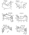
- FIGS 4 and 5 show a first embodiment of a arcuate cutting insert 6, according to the present invention.
- This brochure cutting 6 can be considered as "cut" in a hollow cylinder.
- She thus comprises a concave flank 7, constituted by a first surface cylindrical, and a convex flank 8, constituted by a second surface cylindrical, the two cylindrical surfaces 7 and 8 having the same axis A and thus extending parallel to each other, at a distance defining the constant thickness e of the cutting insert 6.
- the two sides 7 and 8 of the cutting insert 6 are joined by a flat base face 9, which extends in a plane perpendicular to the axis A.
- the two sides 7 and 8 of the cutting insert 6 are also joined by two extreme edges 10 and 11, rectilinear, which extend parallel to the axis A, therefore perpendicular to the base face 9. Finally, the two sides 7 and 8 of the cutting insert 6 are joined, on the side opposite to the base face 9, by a cutting part, here unique.
- the cutting part has two edges of cutting 12 and 13, curved and rising, which start respectively from vertices of the two extreme edges 10 and 11, which converge towards the region a central point 14, the two cutting edges 12 and 13 here being equal length.
- first cutting edge 12 is located between a curved cutting face 15 and a curved undercut face 16.
- the second cutting edge 13 is located between a curved cutting face 17 and a face of curved body 18. In the region of point 14, the two faces of undercut 16 and 18 are adjacent, and are connected along a line 19.
- FIGS. 4 and 5 show a second embodiment of an arcuate cutting insert 6, which is differentiates from the previous one by the asymmetrical arrangement of the two edges cutting 12 and 13 of the single cutting part.
- the two cutting edges 12 and 13 are here, in fact, of unequal length, the first cutting edge 12 having for example a length substantially greater than that of the second cutting edge 13.
- These two cutting edges 12 and 13 are always converging towards the region of a point 14, but this point 14 is here eccentrically.
- Figures 8 to 13 show realizations of plates of arched cut 6 with double cutting part.
- Figures 8 and 9 show a shape in which the arcuate cutting insert 6 has two separate cutting parts, with respective cutting edges 12 and 13, the first cutting edge 12 starting from the top of the extreme edge 10, and the second cutting edge 13 starting from the top of the other extreme edge 11.
- the two cutting parts therefore the two cutting edges 12 and 13, are separated from each other by an intermediate recess 20.
- Figures 10, 11 and 12 show another embodiment, in which the arcuate cutting insert 6 has two cutting parts distinct, constituted respectively by two points 21 and 22 of the type "concrete breaker tip".
- the two points 21 and 22 are located, respectively, towards the vertices of the two extreme edges 10 and 11 of the plate 6, the axes of these points being inclined or parallel with respect to the axis A.
- Both cutting parts, so the two points 21 and 22, are here again separated by an intermediate recess 20, of asymmetrical shape.
- Figure 13 illustrates a variant of this cutting insert arcuate 6 with two points 21 and 22, in which the intermediate recess 20 is symmetrical and looks different.
- the number of points of the type "concrete breaker” may be higher.
- the arcuate cutting insert 6 has two points 21 and 22, located towards its two ends, and a third "concrete breaker" point 23 located in the central part, that is to say between the first two points 21 and 22.
- Figures 14 and 15 show that instead of recesses intermediate, curved cutting edges 12 and 13 may extend between points 21, 22 and 23, and thus make the connection between these points.
- Figures 16 and 17 show a final embodiment, in which the arcuate cutting insert 6, here with a cutting edge with two edges 12 and 13, has on its convex flank 8 a lug or index finger 24, which is used for positioning the wafer 6 in its housing, on the head of cutting a drill or other similar rotary drilling tool.
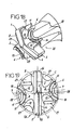
- Figures 18 and 19 show a cutting head 25 of a drill bit, general cylindrical shape finished in conical surface, which receives three cutting inserts.
- the first cutting insert is a flat plate 1 (such as that shown in Figures 1 to 3), arranged diametrically in a corresponding housing in the form of rectilinear groove, formed along a diametrical plane of the cutting head 25.
- the other two cutting inserts are arcuate plates 6 as described above, arranged on the side on the other side of the central plate 1, in corresponding housings of the cutting head 25.
- the respective convex sides 8 of the two inserts arched 6 are turned towards the two large opposite side faces 5 of the flat central plate 1.
- the flat central insert 1 has two cutting edges 3 and 4, which converge towards a point 2 located on the central axis of the cutting head 25 and the drill.
- Each side plate 6 has two other edges of cuts 12 and 13, so that the cutting head 25 has a total of six edges cutting.
- the cutting edges 12 and 13 of the inserts arcuate sides 6 are located substantially at the same level as the edges of cutting 3 and 4 of the flat central insert 1.
- the two extreme edges 26 of the central plate plane 1, and the respective end edges 10 and 11 of the two side plates arcuate 6, are parallel to the axis of the cutting head 25, and all substantially located on the same circle C centered on the axis of the cutting head 25, to constitute six points of support and guide of the drill in a hole being hole, the diameter of which then corresponds to that of circle C.
- the extreme edges 10 and / or 11 of the two arcuate side plates 6 can set back from the circle having the diameter of the joining line the two extreme edges 26 of the flat central plate 1, or else outside this circle.
- longitudinal grooves 27 are dug in the surface lateral cylindrical of the cutting head 25, and open in its face conical terminal, in the gaps between the cutting insert central 1 and the two side cutting inserts 6.
- two other longitudinal grooves 28 are hollowed out at the periphery of the cutting head 25, in the region of the concavity of the two arched side cutting inserts 6. All these grooves 27 and 28, here in total six, contribute to the removal of drilling dust.
- FIGS. 20 and 21 show another cutting head 29 of a drill, which receives a central cutting insert 30, in the shape of a three-star branches 31, and three arcuate side cutting inserts 6, such as previously described.
- the central cutting insert 30 is centered on the axis of the drill, its three branches 31 of planar shape having radial orientations.
- the ends of the three branches 31 of the central plate 30 are located on a circle whose diameter is less than that of the cutting head 29, and less the diameter of the circle through which the extreme edges 10 and 11 of the three pass arched inserts 6.
- the central cutting insert 30 is located "higher" than the arcuate cutting inserts 6, this configuration leading to a cutting head 29 known as "with pilot", this pilot being constituted by the raised central plate 30 and of smaller diameter at the nominal diameter of the drill, the diameter of the drilled hole being defined by the edges outside 10 and 11 of the arched side plates 6.
- the cutting head 29 has, for the evacuation of drilling dust, three peripheral grooves 27 located to the right of the branches 31 of the central cutting insert 30, and three grooves additional peripherals 28 formed in the concavity of the three arched cutting inserts 6.
Landscapes
- Engineering & Computer Science (AREA)
- Geology (AREA)
- Mechanical Engineering (AREA)
- Life Sciences & Earth Sciences (AREA)
- Mining & Mineral Resources (AREA)
- General Life Sciences & Earth Sciences (AREA)
- Fluid Mechanics (AREA)
- Environmental & Geological Engineering (AREA)
- Physics & Mathematics (AREA)
- Geochemistry & Mineralogy (AREA)
- Drilling Tools (AREA)
- Drilling And Boring (AREA)
- Processing Of Stones Or Stones Resemblance Materials (AREA)
- Earth Drilling (AREA)
- Polishing Bodies And Polishing Tools (AREA)
Abstract
Description
- en prévoyant pour la plaquette toute forme arquée, non seulement inscrite dans un cylindre à base circulaire, mais aussi en forme d'arc d'ellipse ou autre, ou encore résultant de l'assemblage de deux ou plusieurs arcs de caractéristiques différentes ;
- en réalisant une plaquette arquée avec deux arêtes de coupe disposées de façon à ce que les faces de dépouille et les faces de coupe respectives se rejoignent toutes sur une pointe située dans la partie centrale de la plaquette ;
- en réalisant une plaquette arquée avec une seule arête de coupe, donc une seule face de coupe et une seule face de dépouille ;
- en prévoyant un ergot ou index de positionnement sur des plaquettes de coupe arquées de toute configuration, avec arêtes de coupe et/ou pointes ;
- en utilisant les plaquettes de coupe arquées en nombre plus ou moins élevé, et dans des dispositions (angulaires et en hauteur) variables, sur des têtes de coupe de forets, conjointement avec une plaquette centrale ou principale de caractéristiques variables, voire même sans plaquette centrale ou principale ;
- en prévoyant ou non, sur le foret, des rainures d'évacuation des poussières dans la région de la concavité des plaquettes de coupe arquées ;
- en destinant ces plaquettes de coupe arquées à des outils de perçage ou forage rotatifs de tous genres, adaptés à divers types de matériaux à percer ;
- en intégrant des arêtes de coupe non linéaires, et de géométrie basée sur celle des plaquettes de coupe arquées précédemment décrites, sur une plaquette monobloc, notamment en carbure, destinée à être soudée ou brasée en bout de foret, ou autre outil de perçage rotatif analogue, afin de réaliser la partie coupante de ce dernier.
Claims (19)
- Plaquette de coupe pour foret, ou autre outil de perçage rotatif analogue, la plaquette (6) étant prévue pour être insérée dans la tête de coupe de l'outil de perçage, caractérisée en ce qu'elle possède une forme générale arquée, avec un flanc concave (7) et un flanc convexe (8), qui sont réunis par une face de base (9), par deux bords extrêmes rectilignes (10, 11) dont l'un au moins est apte à assurer une fonction de guidage pour le foret ou autre outil de perçage, et, du côté opposé à la face de base (9), par au moins une partie coupante, avec au moins une arête de coupe (12, 13) et/ou au moins une pointe (14, 21, 22, 23).
- Plaquette de coupe selon la revendication 1, caractérisée en ce que le flanc concave (7) est constitué par une première surface cylindrique, et le flanc convexe (8) est constitué par une seconde surface cylindrique, les deux surfaces cylindriques étant coaxiales et s'étendant donc parallèlement l'une à l'autre, à une distance définissant une épaisseur (e) constante de la plaquette de coupe arquée (6).
- Plaquette de coupe selon la revendication 1 ou 2, caractérisée en ce que la face de base (9) est une face plane.
- Plaquette de coupe selon l'une quelconque des revendications 1 à 3, caractérisée en ce qu'elle possède une partie coupante unique, continue, pourvue de deux arêtes de coupe (12, 13) montantes, incurvées, qui partent respectivement des sommets des deux bords extrêmes (10, 11) de la plaquette (6), et qui convergent vers la région d'une pointe (14).
- Plaquette de coupe selon la revendication 4, caractérisée en ce que les deux arêtes de coupe (12, 13) incurvées sont d'égale longueur, la plaquette arquée (6) possédant aussi une allure générale symétrique par rapport à un plan médian.
- Plaquette de coupe selon la revendication 4, caractérisée en ce que les deux arêtes de coupe (12, 13) incurvées sont de longueur inégale, et convergent ainsi vers la région d'une pointe (14) excentrée, la plaquette arquée (6) possédant une allure dissymétrique.
- Plaquette de coupe selon l'une quelconque des revendications 1 à 3, caractérisée en ce qu'elle possède deux parties coupantes distinctes avec arêtes de coupe (12, 13) respectives, qui partent respectivement des sommets des deux bords extrêmes (10, 11) de la plaquette (6), et qui sont séparées l'une de l'autre par un évidement intermédiaire (20).
- Plaquette de coupe selon l'une quelconque des revendications 1 à 3, caractérisée en ce qu'elle possède une partie coupante pourvue d'au moins une pointe du type "brise-béton" (21, 22, 23), en particulier deux pointes (21, 22) de ce type situées vers les extrémités de la partie coupante de la plaquette (6).
- Plaquette de coupe selon la revendication 8, caractérisée en ce que les pointes (21, 22, 23) sont combinées avec au moins une arête de coupe (12, 13), qui est présente dans la ou les zones intermédiaires entre les pointes (21, 22, 23), la ou les arêtes (12, 13) faisant ainsi le raccord entre les pointes (21, 22, 23).
- Plaquette de coupe selon la revendication 8, caractérisée en ce que la partie coupante présente au moins un évidement (20), situé entre les pointes (21, 22, 23).
- Plaquette de coupe selon l'une quelconque des revendications 1 à 10, caractérisée en ce qu'elle comporte, sur son flanc concave (7) ou son flanc convexe (8), un ergot ou index (24) pour le positionnement de cette plaquette de coupe (6) dans son logement, au niveau de la tête de coupe (25 ; 29) d'un foret ou autre outil de perçage rotatif.
- Outil de perçage rotatif, du genre foret ou analogue, caractérisé en ce qu'il possède une tête de coupe (25 ; 29) dans laquelle est insérée au moins une plaquette de coupe (6) de forme arquée, selon l'une quelconque des revendications 1 à 11, les bords extrêmes rectilignes (10, 11) de la ou chaque plaquette (6) étant parallèles à l'axe central de l'outil.
- Outil de perçage selon la revendication 12, caractérisé en ce qu'il comprend, au niveau de sa tête de coupe (25 ; 29), d'une part une plaquette centrale ou principale (1 ; 30) de forme plane ou composée de parties planes (31), et d'autre part, disposées sur les côtés de la plaquette centrale ou principale (1), ou autour de cette plaquette centrale ou principale (30), des plaquettes arquées (6) dont les bords extrêmes (10, 11) se situent à la périphérie de la tête de coupe (25 ; 29) de l'outil, les flancs convexes (8) de toutes les plaquettes arquées (6) étant tournées vers la plaquette centrale ou principale (1 ; 30).
- Outil de perçage selon la revendication 13, caractérisé en ce que sa tête de coupe (25) comprend une plaquette centrale plane (1) disposée suivant un diamètre de ladite tête (25), et deux plaquettes latérales arquées (6), disposées de part et d'autre de la plaquette centrale plane (1), les flancs convexes (8) des deux plaquettes arquées (6) étant tournés respectivement vers les deux grandes faces latérales opposées (5) de la plaquette centrale plane (1).
- Outil de perçage selon la revendication 14, caractérisé en ce qu'il possède six points d'appui ou de guidage concentriques (cercle C), constitués par les deux extrémités (26) de la plaquette centrale plane (1), et par les deux extrémités (10, 11) de chacune des deux plaquettes latérales arquées (6).
- Outil de perçage selon la revendication 13, caractérisé en ce que sa tête de coupe (29) comprend une plaquette centrale (30) de forme étoilée, à branches radiales planes (31), centrée sur l'axe de l'outil de perçage, et une pluralité de plaquettes latérales arquées (6) placées dans les secteurs définis entre les branches radiales (31) ou dans le prolongement des branches radiales (31) de la plaquette centrale (30), les flancs convexes (8) des différentes plaquettes arquées (6) étant tournés vers le centre de la plaquette centrale (30).
- Outil de perçage selon la revendication 16, caractérisé en ce que les extrémités des branches (31) de la plaquette centrale (30) sont situées sur un cercle de diamètre inférieur à celui de la tête de coupe (29), la plaquette centrale (30) étant rehaussée par rapport aux plaquettes latérales arquées (6), de manière à réaliser une tête de coupe (29) "avec pilote".
- Outil de perçage selon l'une quelconque des revendications 13 à 17, caractérisé en ce qu'il comporte, à sa périphérie, des rainures longitudinales (28) d'évacuation des poussières de perçage, situées dans la région de la concavité (7) de chacune des plaquettes de coupe arquées (6).
- Outil de perçage rotatif, du genre foret ou analogue, caractérisé en ce qu'il comporte des arêtes de coupe non linéaires, et de géométrie basée sur celle des plaquettes de coupe selon l'une quelconque des revendications 1 à 11, intégrées sur une plaquette monobloc soudée ou brasée en bout d'outil, afin de réaliser la partie coupante de ce dernier.
Applications Claiming Priority (2)
| Application Number | Priority Date | Filing Date | Title |
|---|---|---|---|
| FR0207380A FR2840829B1 (fr) | 2002-06-14 | 2002-06-14 | Plaquette de coupe pour foret, et outil de percage utilisant cette plaquette |
| FR0207380 | 2002-06-14 |
Publications (2)
| Publication Number | Publication Date |
|---|---|
| EP1386684A1 true EP1386684A1 (fr) | 2004-02-04 |
| EP1386684B1 EP1386684B1 (fr) | 2005-05-04 |
Family
ID=29595265
Family Applications (1)
| Application Number | Title | Priority Date | Filing Date |
|---|---|---|---|
| EP03356086A Expired - Lifetime EP1386684B1 (fr) | 2002-06-14 | 2003-06-05 | Outil de percage avec plaquette de coupe |
Country Status (7)
| Country | Link |
|---|---|
| US (1) | US20040001740A1 (fr) |
| EP (1) | EP1386684B1 (fr) |
| CN (1) | CN1468679A (fr) |
| AT (1) | ATE294657T1 (fr) |
| DE (1) | DE60300603T2 (fr) |
| DK (1) | DK1386684T3 (fr) |
| FR (1) | FR2840829B1 (fr) |
Cited By (2)
| Publication number | Priority date | Publication date | Assignee | Title |
|---|---|---|---|---|
| CN103480876A (zh) * | 2013-09-29 | 2014-01-01 | 浙江施克汽车配件有限公司 | 铝罐封口的加工方法 |
| EP2848339B1 (fr) | 2013-09-13 | 2018-03-28 | Irwin Industrial Tool Company | Manche pour outil de forage, outil de forage et procédé de fabrication d'un tel outil |
Families Citing this family (4)
| Publication number | Priority date | Publication date | Assignee | Title |
|---|---|---|---|---|
| CN105312634A (zh) * | 2014-08-04 | 2016-02-10 | 丹阳市博上工具有限公司 | 一种打孔钻头 |
| DE102016211953A1 (de) * | 2016-06-30 | 2018-01-04 | Robert Bosch Gmbh | Bohrwerkzeug |
| CN108556078A (zh) * | 2018-06-21 | 2018-09-21 | 贵州六合门业有限公司 | 圆木开凹槽刀 |
| FI12216U1 (fi) * | 2018-09-03 | 2018-11-15 | Boldan Oy | Putkenpuhdistus- tai avauslaitteen teräpala |
Citations (10)
| Publication number | Priority date | Publication date | Assignee | Title |
|---|---|---|---|---|
| US1847302A (en) * | 1929-02-20 | 1932-03-01 | Cleveland Twist Drill Co | Drill and like implement and method of making same |
| GB758084A (en) * | 1952-09-30 | 1956-09-26 | Joseph Dionisotti | Improvements in rock drills |
| FR1156650A (fr) * | 1956-09-07 | 1958-05-19 | Parisienne De Meches Americain | Perfectionnement apporté aux outils de perçage |
| GB1008029A (en) * | 1963-09-02 | 1965-10-22 | John M Perkins & Smith Ltd | Drill bits |
| GB1062158A (en) * | 1962-12-10 | 1967-03-15 | Metro Cutanit Ltd | Improvements relating to drills |
| EP0763649A1 (fr) * | 1995-09-18 | 1997-03-19 | Diager S.A. | Partie coupante d'un foret |
| DE29721790U1 (de) * | 1997-12-10 | 1998-02-19 | Heller Dinklage Gmbh Geb | Bohrmehlaufnehmender Bohrer |
| EP0947662A1 (fr) * | 1998-04-02 | 1999-10-06 | Plica Werkzeugfabrik Ag | Plaque en métal dur et trépan de roche muni d'une telle plaque |
| EP0972599A2 (fr) * | 1998-07-15 | 2000-01-19 | Sandvik Aktiebolag | Foret pour métal à plaquette coupe avec chevauchement des arêtes de coupe |
| DE29922291U1 (de) * | 1999-12-20 | 2000-02-24 | Drebo Werkzeugfab Gmbh | Bohrer |
Family Cites Families (5)
| Publication number | Priority date | Publication date | Assignee | Title |
|---|---|---|---|---|
| US1136545A (en) * | 1913-04-29 | 1915-04-20 | Joseph D Macdonald | Bit. |
| US1301121A (en) * | 1918-07-23 | 1919-04-22 | Thomas Gordon | Rock-drill. |
| US2099677A (en) * | 1936-03-19 | 1937-11-23 | John P Cunningham | Rock or earth drill bit |
| US2306598A (en) * | 1938-05-05 | 1942-12-29 | Ray E Townsend | Replaceable bit rock drill |
| US2815933A (en) * | 1951-10-02 | 1957-12-10 | Dionisotti Joseph | Detachable drill bit insert for rock boring tools |
-
2002
- 2002-06-14 FR FR0207380A patent/FR2840829B1/fr not_active Expired - Fee Related
-
2003
- 2003-06-05 DE DE60300603T patent/DE60300603T2/de not_active Expired - Lifetime
- 2003-06-05 AT AT03356086T patent/ATE294657T1/de not_active IP Right Cessation
- 2003-06-05 DK DK03356086T patent/DK1386684T3/da active
- 2003-06-05 EP EP03356086A patent/EP1386684B1/fr not_active Expired - Lifetime
- 2003-06-12 US US10/461,533 patent/US20040001740A1/en not_active Abandoned
- 2003-06-13 CN CNA031425747A patent/CN1468679A/zh active Pending
Patent Citations (10)
| Publication number | Priority date | Publication date | Assignee | Title |
|---|---|---|---|---|
| US1847302A (en) * | 1929-02-20 | 1932-03-01 | Cleveland Twist Drill Co | Drill and like implement and method of making same |
| GB758084A (en) * | 1952-09-30 | 1956-09-26 | Joseph Dionisotti | Improvements in rock drills |
| FR1156650A (fr) * | 1956-09-07 | 1958-05-19 | Parisienne De Meches Americain | Perfectionnement apporté aux outils de perçage |
| GB1062158A (en) * | 1962-12-10 | 1967-03-15 | Metro Cutanit Ltd | Improvements relating to drills |
| GB1008029A (en) * | 1963-09-02 | 1965-10-22 | John M Perkins & Smith Ltd | Drill bits |
| EP0763649A1 (fr) * | 1995-09-18 | 1997-03-19 | Diager S.A. | Partie coupante d'un foret |
| DE29721790U1 (de) * | 1997-12-10 | 1998-02-19 | Heller Dinklage Gmbh Geb | Bohrmehlaufnehmender Bohrer |
| EP0947662A1 (fr) * | 1998-04-02 | 1999-10-06 | Plica Werkzeugfabrik Ag | Plaque en métal dur et trépan de roche muni d'une telle plaque |
| EP0972599A2 (fr) * | 1998-07-15 | 2000-01-19 | Sandvik Aktiebolag | Foret pour métal à plaquette coupe avec chevauchement des arêtes de coupe |
| DE29922291U1 (de) * | 1999-12-20 | 2000-02-24 | Drebo Werkzeugfab Gmbh | Bohrer |
Cited By (3)
| Publication number | Priority date | Publication date | Assignee | Title |
|---|---|---|---|---|
| EP2848339B1 (fr) | 2013-09-13 | 2018-03-28 | Irwin Industrial Tool Company | Manche pour outil de forage, outil de forage et procédé de fabrication d'un tel outil |
| CN103480876A (zh) * | 2013-09-29 | 2014-01-01 | 浙江施克汽车配件有限公司 | 铝罐封口的加工方法 |
| CN103480876B (zh) * | 2013-09-29 | 2016-04-06 | 浙江施克汽车配件有限公司 | 铝罐封口的加工方法 |
Also Published As
| Publication number | Publication date |
|---|---|
| DK1386684T3 (da) | 2005-09-05 |
| FR2840829A1 (fr) | 2003-12-19 |
| US20040001740A1 (en) | 2004-01-01 |
| EP1386684B1 (fr) | 2005-05-04 |
| DE60300603D1 (de) | 2005-06-09 |
| FR2840829B1 (fr) | 2005-01-14 |
| ATE294657T1 (de) | 2005-05-15 |
| CN1468679A (zh) | 2004-01-21 |
| DE60300603T2 (de) | 2006-01-19 |
Similar Documents
| Publication | Publication Date | Title |
|---|---|---|
| BE1013071A5 (fr) | Element de coupe a surface de contact superabrasive controlee, trepans de forage ainsi equipes et procedes de forage. | |
| LU83605A1 (fr) | Piece rapportee de coupe | |
| EP0944765A1 (fr) | Outil de forage et/ou de carottage | |
| FR2909574A1 (fr) | Mandrin de serrage. | |
| EP1737597A1 (fr) | Plaquette de coupe a nombre limite de faces de cadrage | |
| FR2704785A1 (fr) | Perfectionnements aux outils pour la réalisation de points d'assemblage de tôles par fluage à froid. | |
| EP1386684B1 (fr) | Outil de percage avec plaquette de coupe | |
| FR2462958A1 (fr) | Outil de coupe comportant des dents ayant une gorge diviseuse de copeaux | |
| FR2808462A1 (fr) | Foret de percage | |
| FR2552354A1 (fr) | Outil de coupe annulaire destine a percer des trous | |
| EP1072338B1 (fr) | Outil pour démonter des rivets et procédé de démontage de rivets correspondant | |
| FR2779366A1 (fr) | Foret a levres de coupe multiples | |
| FR2656554A1 (fr) | Outil de percage de precision pour materiaux composites. | |
| EP3003619B1 (fr) | Outil coupant rotatif presentant une arete de coupe en plusieurs materiaux. | |
| WO2000067939A1 (fr) | Foret helicoidal a trous d'huile | |
| EP0066079B1 (fr) | Fraise à percer-rainurer | |
| FR2878772A1 (fr) | Plaquette de coupe pour outil de percage rotatif | |
| FR2935288A3 (fr) | Coin a refendre. | |
| FR2703610A1 (fr) | Plaquette de coupe et outil équipé de telles plaquettes . | |
| EP1725361A1 (fr) | Porte-outil rotatif a plaquette dissymetrique | |
| FR2469250A1 (fr) | Embout cruciforme pour outil de vissage | |
| BE1008044A5 (fr) | Segment de coupe a concretion diamantee. | |
| EP0155233B1 (fr) | Tête de poussoir pour ravitailleur pour tour automatique | |
| EP0083287A1 (fr) | Bouton en matériau dur pour outil de perforation | |
| EP1617963B1 (fr) | Outil de coupe a plaquette rapportee |
Legal Events
| Date | Code | Title | Description |
|---|---|---|---|
| PUAI | Public reference made under article 153(3) epc to a published international application that has entered the european phase |
Free format text: ORIGINAL CODE: 0009012 |
|
| AK | Designated contracting states |
Kind code of ref document: A1 Designated state(s): AT BE BG CH CY CZ DE DK EE ES FI FR GB GR HU IE IT LI LU MC NL PT RO SE SI SK TR |
|
| AX | Request for extension of the european patent |
Extension state: AL LT LV MK |
|
| 17P | Request for examination filed |
Effective date: 20040202 |
|
| 17Q | First examination report despatched |
Effective date: 20040426 |
|
| AKX | Designation fees paid |
Designated state(s): AT BE BG CH CY CZ DE DK EE ES FI FR GB GR HU IE IT LI LU MC NL PT RO SE SI SK TR |
|
| AXX | Extension fees paid |
Extension state: AL Payment date: 20040202 Extension state: LT Payment date: 20040202 Extension state: LV Payment date: 20040202 Extension state: MK Payment date: 20040202 |
|
| GRAP | Despatch of communication of intention to grant a patent |
Free format text: ORIGINAL CODE: EPIDOSNIGR1 |
|
| RTI1 | Title (correction) |
Free format text: DRILL BIT WITH CUTTING INSERT |
|
| GRAS | Grant fee paid |
Free format text: ORIGINAL CODE: EPIDOSNIGR3 |
|
| GRAA | (expected) grant |
Free format text: ORIGINAL CODE: 0009210 |
|
| AK | Designated contracting states |
Kind code of ref document: B1 Designated state(s): AT BE BG CH CY CZ DE DK EE ES FI FR GB GR HU IE IT LI LU MC NL PT RO SE SI SK TR |
|
| AX | Request for extension of the european patent |
Extension state: AL LT LV MK |
|
| PG25 | Lapsed in a contracting state [announced via postgrant information from national office to epo] |
Ref country code: IT Free format text: LAPSE BECAUSE OF FAILURE TO SUBMIT A TRANSLATION OF THE DESCRIPTION OR TO PAY THE FEE WITHIN THE PRESCRIBED TIME-LIMIT;WARNING: LAPSES OF ITALIAN PATENTS WITH EFFECTIVE DATE BEFORE 2007 MAY HAVE OCCURRED AT ANY TIME BEFORE 2007. THE CORRECT EFFECTIVE DATE MAY BE DIFFERENT FROM THE ONE RECORDED. Effective date: 20050504 Ref country code: CZ Free format text: LAPSE BECAUSE OF FAILURE TO SUBMIT A TRANSLATION OF THE DESCRIPTION OR TO PAY THE FEE WITHIN THE PRESCRIBED TIME-LIMIT Effective date: 20050504 Ref country code: IE Free format text: LAPSE BECAUSE OF FAILURE TO SUBMIT A TRANSLATION OF THE DESCRIPTION OR TO PAY THE FEE WITHIN THE PRESCRIBED TIME-LIMIT Effective date: 20050504 Ref country code: NL Free format text: LAPSE BECAUSE OF FAILURE TO SUBMIT A TRANSLATION OF THE DESCRIPTION OR TO PAY THE FEE WITHIN THE PRESCRIBED TIME-LIMIT Effective date: 20050504 Ref country code: SK Free format text: LAPSE BECAUSE OF FAILURE TO SUBMIT A TRANSLATION OF THE DESCRIPTION OR TO PAY THE FEE WITHIN THE PRESCRIBED TIME-LIMIT Effective date: 20050504 Ref country code: AT Free format text: LAPSE BECAUSE OF FAILURE TO SUBMIT A TRANSLATION OF THE DESCRIPTION OR TO PAY THE FEE WITHIN THE PRESCRIBED TIME-LIMIT Effective date: 20050504 Ref country code: GB Free format text: LAPSE BECAUSE OF FAILURE TO SUBMIT A TRANSLATION OF THE DESCRIPTION OR TO PAY THE FEE WITHIN THE PRESCRIBED TIME-LIMIT Effective date: 20050504 Ref country code: TR Free format text: LAPSE BECAUSE OF FAILURE TO SUBMIT A TRANSLATION OF THE DESCRIPTION OR TO PAY THE FEE WITHIN THE PRESCRIBED TIME-LIMIT Effective date: 20050504 Ref country code: RO Free format text: LAPSE BECAUSE OF FAILURE TO SUBMIT A TRANSLATION OF THE DESCRIPTION OR TO PAY THE FEE WITHIN THE PRESCRIBED TIME-LIMIT Effective date: 20050504 Ref country code: FI Free format text: LAPSE BECAUSE OF FAILURE TO SUBMIT A TRANSLATION OF THE DESCRIPTION OR TO PAY THE FEE WITHIN THE PRESCRIBED TIME-LIMIT Effective date: 20050504 Ref country code: EE Free format text: LAPSE BECAUSE OF FAILURE TO SUBMIT A TRANSLATION OF THE DESCRIPTION OR TO PAY THE FEE WITHIN THE PRESCRIBED TIME-LIMIT Effective date: 20050504 Ref country code: SI Free format text: LAPSE BECAUSE OF FAILURE TO SUBMIT A TRANSLATION OF THE DESCRIPTION OR TO PAY THE FEE WITHIN THE PRESCRIBED TIME-LIMIT Effective date: 20050504 |
|
| REG | Reference to a national code |
Ref country code: GB Ref legal event code: FG4D Free format text: NOT ENGLISH |
|
| REG | Reference to a national code |
Ref country code: CH Ref legal event code: EP |
|
| REG | Reference to a national code |
Ref country code: IE Ref legal event code: FG4D Free format text: LANGUAGE OF EP DOCUMENT: FRENCH |
|
| PG25 | Lapsed in a contracting state [announced via postgrant information from national office to epo] |
Ref country code: CY Free format text: LAPSE BECAUSE OF FAILURE TO SUBMIT A TRANSLATION OF THE DESCRIPTION OR TO PAY THE FEE WITHIN THE PRESCRIBED TIME-LIMIT Effective date: 20050605 Ref country code: LU Free format text: LAPSE BECAUSE OF NON-PAYMENT OF DUE FEES Effective date: 20050605 |
|
| REF | Corresponds to: |
Ref document number: 60300603 Country of ref document: DE Date of ref document: 20050609 Kind code of ref document: P |
|
| PG25 | Lapsed in a contracting state [announced via postgrant information from national office to epo] |
Ref country code: MC Free format text: LAPSE BECAUSE OF NON-PAYMENT OF DUE FEES Effective date: 20050630 Ref country code: BE Free format text: LAPSE BECAUSE OF NON-PAYMENT OF DUE FEES Effective date: 20050630 |
|
| PG25 | Lapsed in a contracting state [announced via postgrant information from national office to epo] |
Ref country code: SE Free format text: LAPSE BECAUSE OF FAILURE TO SUBMIT A TRANSLATION OF THE DESCRIPTION OR TO PAY THE FEE WITHIN THE PRESCRIBED TIME-LIMIT Effective date: 20050804 Ref country code: BG Free format text: LAPSE BECAUSE OF FAILURE TO SUBMIT A TRANSLATION OF THE DESCRIPTION OR TO PAY THE FEE WITHIN THE PRESCRIBED TIME-LIMIT Effective date: 20050804 Ref country code: GR Free format text: LAPSE BECAUSE OF FAILURE TO SUBMIT A TRANSLATION OF THE DESCRIPTION OR TO PAY THE FEE WITHIN THE PRESCRIBED TIME-LIMIT Effective date: 20050804 |
|
| PG25 | Lapsed in a contracting state [announced via postgrant information from national office to epo] |
Ref country code: ES Free format text: LAPSE BECAUSE OF FAILURE TO SUBMIT A TRANSLATION OF THE DESCRIPTION OR TO PAY THE FEE WITHIN THE PRESCRIBED TIME-LIMIT Effective date: 20050815 |
|
| REG | Reference to a national code |
Ref country code: DK Ref legal event code: T3 |
|
| PG25 | Lapsed in a contracting state [announced via postgrant information from national office to epo] |
Ref country code: PT Free format text: LAPSE BECAUSE OF FAILURE TO SUBMIT A TRANSLATION OF THE DESCRIPTION OR TO PAY THE FEE WITHIN THE PRESCRIBED TIME-LIMIT Effective date: 20051017 |
|
| LTIE | Lt: invalidation of european patent or patent extension |
Effective date: 20050504 |
|
| NLV1 | Nl: lapsed or annulled due to failure to fulfill the requirements of art. 29p and 29m of the patents act | ||
| PG25 | Lapsed in a contracting state [announced via postgrant information from national office to epo] |
Ref country code: HU Free format text: LAPSE BECAUSE OF FAILURE TO SUBMIT A TRANSLATION OF THE DESCRIPTION OR TO PAY THE FEE WITHIN THE PRESCRIBED TIME-LIMIT Effective date: 20051105 |
|
| GBV | Gb: ep patent (uk) treated as always having been void in accordance with gb section 77(7)/1977 [no translation filed] |
Effective date: 20050504 |
|
| REG | Reference to a national code |
Ref country code: IE Ref legal event code: FD4D |
|
| PLBE | No opposition filed within time limit |
Free format text: ORIGINAL CODE: 0009261 |
|
| STAA | Information on the status of an ep patent application or granted ep patent |
Free format text: STATUS: NO OPPOSITION FILED WITHIN TIME LIMIT |
|
| 26N | No opposition filed |
Effective date: 20060207 |
|
| BERE | Be: lapsed |
Owner name: DIAGER Effective date: 20050630 |
|
| PGFP | Annual fee paid to national office [announced via postgrant information from national office to epo] |
Ref country code: CH Payment date: 20080522 Year of fee payment: 6 Ref country code: DK Payment date: 20080520 Year of fee payment: 6 |
|
| REG | Reference to a national code |
Ref country code: CH Ref legal event code: PL |
|
| REG | Reference to a national code |
Ref country code: DK Ref legal event code: EBP |
|
| PG25 | Lapsed in a contracting state [announced via postgrant information from national office to epo] |
Ref country code: CH Free format text: LAPSE BECAUSE OF NON-PAYMENT OF DUE FEES Effective date: 20090630 Ref country code: LI Free format text: LAPSE BECAUSE OF NON-PAYMENT OF DUE FEES Effective date: 20090630 |
|
| PG25 | Lapsed in a contracting state [announced via postgrant information from national office to epo] |
Ref country code: DK Free format text: LAPSE BECAUSE OF NON-PAYMENT OF DUE FEES Effective date: 20090630 |
|
| PGFP | Annual fee paid to national office [announced via postgrant information from national office to epo] |
Ref country code: FR Payment date: 20100615 Year of fee payment: 8 |
|
| PGFP | Annual fee paid to national office [announced via postgrant information from national office to epo] |
Ref country code: DE Payment date: 20100614 Year of fee payment: 8 |
|
| REG | Reference to a national code |
Ref country code: FR Ref legal event code: ST Effective date: 20120229 |
|
| REG | Reference to a national code |
Ref country code: DE Ref legal event code: R119 Ref document number: 60300603 Country of ref document: DE Effective date: 20120103 |
|
| PG25 | Lapsed in a contracting state [announced via postgrant information from national office to epo] |
Ref country code: DE Free format text: LAPSE BECAUSE OF NON-PAYMENT OF DUE FEES Effective date: 20120103 Ref country code: FR Free format text: LAPSE BECAUSE OF NON-PAYMENT OF DUE FEES Effective date: 20110630 |