EP1386416B1 - Verfahren und system zur ausnutzung der polarisationswiederverwendung in drahtlosen übermittlungen - Google Patents
Verfahren und system zur ausnutzung der polarisationswiederverwendung in drahtlosen übermittlungen Download PDFInfo
- Publication number
- EP1386416B1 EP1386416B1 EP02736691A EP02736691A EP1386416B1 EP 1386416 B1 EP1386416 B1 EP 1386416B1 EP 02736691 A EP02736691 A EP 02736691A EP 02736691 A EP02736691 A EP 02736691A EP 1386416 B1 EP1386416 B1 EP 1386416B1
- Authority
- EP
- European Patent Office
- Prior art keywords
- signal
- polarization
- pilot signals
- pilot
- polarized
- Prior art date
- Legal status (The legal status is an assumption and is not a legal conclusion. Google has not performed a legal analysis and makes no representation as to the accuracy of the status listed.)
- Expired - Lifetime
Links
Images

Classifications
-
- H—ELECTRICITY
- H04—ELECTRIC COMMUNICATION TECHNIQUE
- H04B—TRANSMISSION
- H04B1/00—Details of transmission systems, not covered by a single one of groups H04B3/00 - H04B13/00; Details of transmission systems not characterised by the medium used for transmission
- H04B1/76—Pilot transmitters or receivers for control of transmission or for equalising
-
- H—ELECTRICITY
- H04—ELECTRIC COMMUNICATION TECHNIQUE
- H04B—TRANSMISSION
- H04B7/00—Radio transmission systems, i.e. using radiation field
- H04B7/02—Diversity systems; Multi-antenna system, i.e. transmission or reception using multiple antennas
- H04B7/04—Diversity systems; Multi-antenna system, i.e. transmission or reception using multiple antennas using two or more spaced independent antennas
- H04B7/0491—Diversity systems; Multi-antenna system, i.e. transmission or reception using multiple antennas using two or more spaced independent antennas using two or more sectors, i.e. sector diversity
-
- H—ELECTRICITY
- H04—ELECTRIC COMMUNICATION TECHNIQUE
- H04B—TRANSMISSION
- H04B7/00—Radio transmission systems, i.e. using radiation field
- H04B7/02—Diversity systems; Multi-antenna system, i.e. transmission or reception using multiple antennas
- H04B7/10—Polarisation diversity; Directional diversity
-
- H—ELECTRICITY
- H04—ELECTRIC COMMUNICATION TECHNIQUE
- H04W—WIRELESS COMMUNICATION NETWORKS
- H04W72/00—Local resource management
- H04W72/50—Allocation or scheduling criteria for wireless resources
- H04W72/54—Allocation or scheduling criteria for wireless resources based on quality criteria
- H04W72/541—Allocation or scheduling criteria for wireless resources based on quality criteria using the level of interference
Definitions
- the present invention generally relates to the field of wireless communication systems, and more specifically to techniques using antenna polarization in wireless communication system.
- CDMA code division multiple access
- each signal is separated from those of other users by coding the signal.
- Each user uniquely encodes its information signal into a transmission signal. The intended receiver, knowing the code sequences of the user, can decode the transmission signal to receive the information.
- a technique for increasing the signal to interference ratio is to use different frequencies in different cells, or even in different sectors within a cell in order to increase signal to interference ratio.
- a cell can be divided into three sectors, each assigned a different frequency.
- the same frequencies can be similarly allocated in other cells in the system, which is known as frequency reuse.
- adjacent sectors are allocated different frequencies the interference between their signals is reduced, and the signal to interference ratio for users in the two adjacent sectors is increased. Therefore, the sectors' capacity is increased with frequency reuse, but the disadvantage is that frequency reuse necessitates using more frequencies.
- Embodiments disclosed herein address the above stated needs by using polarization of radio signals as an additional resource to enhance and complement presently known approaches to channel allocation in order to further increase signal to interference ratios at a receiver terminal.
- Polarization of radio signals as a means for increasing signal to interference ratios requires minimal expenditure of additional system resources such as the allocation of more frequencies.
- a wireless access terminal receives a first plurality of pilot signals of a first polarization, which can be, for example, vertical polarization.
- the pilot signals contain a data sequence which can be used to identify the sector and/or base transceiver station transmitting the pilot signals.
- the first plurality of pilot signals is ranked.
- a second plurality of pilot signals is received of a second polarization, which can be, for example, horizontal polarization, and the second plurality of pilot signals is ranked.
- a pilot signal from the first and second pluralities of pilot signals received and ranked is selected based on a signal quality measurement.
- the signal quality measurement can be, for example, a signal to interference ratio.
- a system in another aspect, can be constructed comprising antennas configured to receive orthogonally polarized pilot signals.
- the system further comprises a receiver configured to demodulate the pilot signals and a CPU configured to rank the pilot signals and to select a pilot signal based on a signal quality measurement.
- the signal quality measurement can be, for example, a signal to interference ratio.
- the present invention is directed to method and system for utilizing polarization reuse in wireless communications.
- the principles of the invention, as defined by the claims appended herein, can obviously be applied beyond the embodiments of the description described specifically herein.
- certain details have been left out in order to not obscure the inventive aspects of the invention.
- the specific details not described in the present application are within the knowledge of a person of ordinary skill in the art.
- FIG. 1 illustrates an exemplary wireless communication system in accordance with one embodiment.
- Exemplary wireless communication system 100 shown in Figure 1 can comprise, for example, part of a code division multiple access (“CDMA") communication system.
- system 100 can be a frequency division multiple access (“FDMA”) system, a time division multiple access (“TDMA”) system, a wideband code division multiple access (“WCDMA”), a high data rate (“HDR”) system, or in general any wireless communication system employing a combination of CDMA, TDMA, and/or FDMA techniques.
- CDMA code division multiple access
- TDMA time division multiple access
- WCDMA wideband code division multiple access
- HDR high data rate
- the present invention is discussed in relation to a CDMA communication system.
- the invention can be used in other communications systems as stated above.
- the general principles of CDMA communication systems, and in particular the general principles for generation of spread spectrum signals for transmission over a communication channel is described in U.S. patent 4,901,307 entitled “Spread Spectrum Multiple Access Communication System Using Satellite or Terrestrial Repeaters” and assigned to the assignee of the present invention.
- U.S. patent 5,103,459 entitled “System and Method for Generating Signal Waveforms in a CDMA Cellular Telephone System” and assigned to the assignee of the present invention discloses principles related to PN spreading, Walsh covering, and techniques to generate CDMA spread spectrum communication signals.
- the present invention utilizes time multiplexing of data and various principles related to "high data rate” communication systems, and the present invention can be used in "high data rate” communication systems, such as that disclosed in U.S. patent application entitled “Method and Apparatus for High Rate Packet Data Transmission” Serial No. 08/963,386 filed on November 3, 1997 , and assigned to the assignee of the present invention.
- exemplary wireless communication system 100 which can be a CDMA communication system, comprises components typically found in wireless communication systems, including a wireless access terminal such as wireless modem 110, base transceiver station (“BTS”) 134, base station controller (“BSC") 136, mobile switching center (“MSC”) 138, public switched telephone network (“PSTN”) 140, and Internet service provider (“ISP”) 142.
- BTS 134 which is also referred to as a "base station” in the present application, serves as a radio link between the wireless access terminal, e.g. wireless modem 110, and the rest of the system.
- BTS 134 comprises vertically polarized BTS antenna 130, which is configured to transmit and receive vertically polarized radio signals, and horizontally polarized BTS antenna 132, which is configured to transmit and receive horizontally polarized radio signals.
- a vertically polarized antenna such as vertically polarized BTS antenna 130
- a horizontally polarized antenna such as horizontally polarized BTS antenna 132
- BTS 134 can comprise a right hand circular polarized antenna and a left hand circular polarized antenna configured to transmit and receive circular polarized radio signals.
- connections between BTS 134, BSC 136, MSC 138, PSTN 140, and ISP 142 can be wired, wireless, or both.
- Wireless modem 110 in Figure 1 includes, among other components which are not shown in Figure 1 , central processing unit (“CPU”) 112, read only memory module (“ROM”) 114, flash memory module 116, random access memory module (“RAM”) 118, and transmitter and receiver 120.
- bus 122 couples CPU 112, ROM 114, flash memory module 116, RAM 118, and transmitter and receiver 120.
- wireless modem 110 comprises vertically polarized modem antenna 124 and horizontally polarized modem antenna 126.
- Vertically polarized modem antenna 124 is configured to receive and transmit vertically polarized radio signals
- horizontally polarized modem antenna 126 is configured to receive and transmit horizontally polarized radio signals.
- wireless modem 110 can comprise a right hand circular polarized antenna and a left hand circular polarized antenna configured to receive and transmit circular polarized radio signals. It is noted that wireless modem 110 is also referred to as a "polarized reception system" in the present application.
- communication between wireless modem 110 and BTS 134 is achieved by the transmission and reception of polarized radio signals.
- BTS 134 can communicate with wireless modem 110 by using vertically polarized BTS antenna 130 to transmit vertically polarized radio signals that are received by vertically polarized modem antenna 124.
- communication between wireless modem 110 and BTS 134 could involve horizontally polarized BTS antenna 132 transmitting a horizontally polarized radio signal that is received by horizontally polarized modem antenna 126.
- PSTN 140 refers to a conventional wireline telephone network
- ISP 142 refers to services providing access to the Internet.
- Data and voice information provided by ISP 142 and PSTN 140 can be communicated to wireless modem 110 by being routed through MSC 138, BSC 136, and BTS 134.
- MSC 138 functions generally as a switch between the wireless network and PSTN 140 and ISP 142, while the role of BSC 136, among others, is to manage the signal transmission power of BTS 134.
- Internet data can be communicated to wireless modem 110 by being routed from ISP 142 through MSC 138, BSC 136, and to BTS 134 in order for BTS 134 to transmit the data to wireless modem 110 as radio frequency signals on both vertically polarized BTS antenna 130 and horizontally polarized BTS antenna 132 in a manner known in the art.
- BTS 134 can, for example, transmit radio frequency signals as vertically polarized radio signals transmitted by vertically polarized BTS antenna 130 that are generally received by vertically polarized modem antenna 124.
- the radio frequency signals are demodulated by transmitter and receiver 120 and the information extracted at wireless modem 110. Communication between ISP 142 and wireless modem 110 is thereby completed.
- Figure 1 shows a block diagram of an exemplary wireless communication system in which communication between a base transceiver station and a wireless modem is accomplished by means of polarized radio signals.
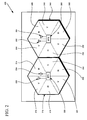
- FIG. 2 illustrates a two cell array in a wireless communication system in accordance with one embodiment.
- Cell array 200 shown in Figure 2 comprises a geographical region in a wireless communication system, which can be, for example, a CDMA communication system.
- Cell array 200 comprises cell 210 and cell 240 which are defined by solid lines and shown as hexagons in Figure 2 .
- cell 210 is divided into six sectors, which are sector 214, sector 216, sector 218, sector 220, sector 222, and sector 224. Sectors 214, 216, 218, 220, 222, and 224 are defined by dashed lines in Figure 2 .
- cell 240 comprises six sectors, which are sectors 244, 246, 248, 250, 252, and 254 which are also defined by dashed lines.
- cell 210 of cell array 200 comprises base transceiver station ("BTS") 230 positioned at the center of cell 210.
- BTS 230 is equipped with vertically polarized BTS antenna 232 and horizontally polarized BTS antenna 234.
- Vertically polarized BTS antenna 232 is configured to transmit and receive vertically polarized radio signals
- horizontally polarized BTS antenna 234 is configured to transmit and receive horizontally polarized radio signals.
- BTS 230 can communicate with wireless access terminals in cell array 200 using polarized radio signals.
- Wireless access terminals are not shown in Figure 2 , but can be, for example, a wireless modem such as wireless modem 110 shown in Figure 1 .
- BTS 230 is a sectorized base transceiver station.
- BTS 230 continuously broadcasts a pilot signal in each sector of cell 210 on the polarization designated for that particular sector.
- BTS 230 utilizes vertically polarized BTS antenna 232 to transmit vertically polarized pilot signals to sectors 216, 220 and 224 and utilizes horizontally polarized BTS antenna 234 to transmit horizontally polarized pilot signals to sectors 214, 218 and 222.
- data from BTS 230 is transmitted in frames where each data frame contains an initial pilot sequence as well as a subsequent message data sequence. As an example, the initial pilot sequence may take up approximately 5% of the entire data frame.
- the pilot sequence is generally a known data sequence recognizable to a receiving wireless access terminal.
- a receiving wireless access terminal can use the data sequence contained in a pilot signal to identify the particular sector and base transceiver station transmitting the particular pilot signal.
- a wireless access terminal such as wireless modem 110 in Figure 1 , equipped with both vertically and horizontally polarized antennas would have the capability to receive both vertically and horizontally polarized pilot signals transmitted by BTS 230.
- BTS 260 Base transceiver station 260
- BTS 260 is situated at the center of cell 210 and comprises vertically polarized BTS antenna 262 and horizontally polarized BTS antenna 264 which are configured to transmit and receive, respectively, vertically and horizontally polarized radio signals.
- BTS 260 is a sectorized base transceiver station which continuously broadcasts a pilot signal to each sector of cell 240 on the polarization assigned to that sector.
- BTS 260 utilizes vertically polarized BTS antenna 262 to transmit vertically polarized pilot signals to sectors 244, 248 and 252 and utilizes horizontally polarized BTS antenna 264 to transmit horizontally polarized pilot signals to sectors 246, 250 and 254.
- the pilot signals transmitted by BTS 260 can be received by wireless access terminals in cell array 200 equipped with vertically and horizontally polarized antennas.
- a wireless access terminal can use, for example, the unique data sequence contained in the pilot signals it receives to identify a particular sector and base transceiver station transmitting a particular pilot signal.
- Figure 2 thus illustrates a two cell array in an exemplary communication system wherein base transceiver stations situated at the center of the cells are equipped with polarized antennas to transmit polarized pilot signals in each sector.
- the pilot signals are received by wireless access terminals which utilize a unique data sequence contained in the pilot signals in order to identify the particular sector and base transceiver station transmitting the pilot signal.
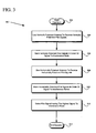
- flow chart 300 illustrates an example method for selecting a pilot signal having a highest signal to interference ratio in accordance with one embodiment.
- the signal to interference ratio is a quantification of the power of the desired signal to interference signals.
- the signal to interference ratio therefore indicates the signal quality of the received data signal.
- the process illustrated in flow chart 300 in Figure 3 describes the process as performed by a wireless access terminal in a wireless communication system, which can be, for example, a CDMA communication system.
- the process shown in flow chart 300 is described in the context of wireless modem 110 in Figure 1 and exemplary cell array 200 in Figure 2 . As such, it is manifest that the process illustrated in flow chart 300 can be practiced by an access terminal other than wireless modem 110 and in a wireless environment other than cell array 200.
- Flow chart 300 illustrates the process of selecting a pilot signal having a highest signal to interference ratio beginning at step 302.
- the process continues at step 304 where a wireless access terminal using a vertically polarized antenna receives vertically polarized pilot signals transmitted by base transceiver stations situated throughout the wireless communication system.
- wireless modem 110 can use vertically polarized modem antenna 124 to receive vertically polarized pilot signals transmitted by vertically polarized BTS antenna 232 and vertically polarized BTS antenna 262.
- vertically polarized modem antenna 124 may receive vertically polarized pilot signals transmitted throughout cell array 200, i.e. vertically polarized pilot signals transmitted by both vertically polarized BTS antenna 232 and vertically polarized BTS antenna 262. At the same time, vertically polarized modem antenna 124 may not receive all of the vertically polarized pilot signals transmitted by vertically polarized BTS antenna 232 and vertically polarized BTS antenna 262, depending on, for example, the power of the transmission, as well as the distance and terrain between vertically polarized modem antenna 124 and vertically polarized BTS antennas 232 and 262.
- radio signals lose their power over distance and can also be reflected by obstacles such as hills, buildings, and trees in their paths.
- the radio signals containing the pilot signals reach vertically polarized modem antenna 124, some of the pilot signals may be too weak to be received.
- vertically polarized modem antenna 124 receives the various pilot signals at different reception power or signal to interference ratios.
- the information signal can comprise, for example, a data sequence which identifies the base transceiver station and the sector transmitting the pilot signals. The steps involved in the demodulation of radio signals is generally known in the art.
- the vertically polarized pilot signals received by vertically polarized modem antenna 124 at wireless modem 110 are ranked by their signal to interference ratios.
- Ranking of vertically polarized pilot signals by their signal to interference ratios involves measuring the signal quality of each pilot signal received, comparing the signal quality of the pilot signals to one another, and ordering the pilot signals by their signal to interference ratios.
- Ranking of vertically polarized pilot signals by their signal to interference ratio can be performed, for example, by software running on CPU 112. The ranking can be stored, for example, in flash memory 116.
- wireless modem 110 switches from vertically polarized modem antenna 124 to horizontally polarized modem antenna 126 in order to receive horizontally polarized pilot signals.
- the horizontally polarized pilot signals are transmitted continuously by horizontally polarized BTS antennas 234 and 264 in cell array 200. And because radio signals can overlap into nearby cells and sectors, as discussed above, horizontally polarized modem antenna 126 may receive horizontally polarized pilot signals form throughout cell array 200.
- the horizontally polarized pilot signals are received by horizontally polarized modem antenna 126 at different signal to interference ratios, depending on, for example, the distance and type of terrain between horizontally polarized modem antenna 126 and the horizontally polarized BTS antennas transmitting the pilot signals.
- the horizontally polarized pilot signals received by horizontally polarized modem antenna 126 are ranked by their signal to interference ratios.
- the ranking of horizontally polarized pilot signals can involve, for example, measuring the signal quality of each pilot signal, comparing the signal quality of the pilot signals, and ordering the pilot signals in sequence of their signal to interference ratios.
- Ranking horizontally polarized pilot signals by their signal to interference ratio can be performed, for example, by software running on CPU 112. The ranking can be stored, for example, in flash memory 116.
- the ranking of vertically polarized pilot signals is compared to the ranking of horizontally polarized pilot signals.
- the pilot signal having the highest signal to interference ratio overall can be selected.
- the signal to interference ratio for a pilot signal indicates the signal quality of the initial pilot sequence in a data frame as well as the signal quality of the message data sequence in the data frame received from the base transceiver station on the particular sector transmitting the pilot signal.
- the operation for selecting a pilot signal having the highest signal to interference ratio then ends at step 314.
- wireless modem 110 uses the information contained in the pilot signal to identify and select the sector and base transceiver station transmitting the pilot signal.
- Wireless modem 110 sends an identification signal ("ID signal") to the base transceiver station transmitting the pilot signal.
- ID signal can be, for example, an electronic serial number unique to wireless modem 110 which identifies wireless modem 110 to the base transceiver station.
- the ID signal informs the particular base transceiver station that wireless modem 110 has selected to communicate with that station on the particular sector which wireless modem 110 has determined to have the highest signal quality. It is noted that the ID signal is also referred to as a "sector identification" in the present application.
- flow chart 300 in Figure 3 illustrates a process for selecting a pilot signal having the highest signal to interference ratio and communicating with the sector and base transceiver station transmitting the pilot signal having the highest signal to interference ratio so as to improve signal reception quality in accordance with one embodiment.
- the steps shown in flow chart 300 to receive and rank pilot signals, and thereafter communicate with a selected base station on a sector having the highest quality signal are repeated periodically, such as every few days.
- the reason is that due to terrain changes, for example changes in the configuration of obstacles such as buildings and trees in the signal path, it is necessary to periodically determine whether a different base transceiver station and/or a different sector should be used for communication with wireless modem 110.
- the present example uses the signal to interference ratio as the signal quality measurement for ranking and selecting pilot signals, it is manifest that other signal quality measurements can be used. For example, a signal to noise ratio measurement can also be used.
- the present application was discussed in relation to vertically polarized and horizontally polarized signals, the invention can also be used with right hand circular polarized and left hand circular polarized signals.
- a wireless access terminal such as wireless modem 110 utilizes the process set forth in Figure 3 to receive and select a polarized pilot signal having a highest signal to interference ratio. Subsequently, the wireless access terminal communicates with a number of sectors corresponding to one or more base transceiver stations on the same polarization as the polarization of the pilot signal providing the highest signal to interference ratio. Each of the sectors of the one or more base transceiver stations would be configured to transmit on the same polarization as the polarization of the pilot signal.
- the wireless access terminal would communicate with a number of "vertically polarized sectors" in one or more base transceiver stations by means of vertically polarized radio signals.
- the vertically polarized signals from the base transceiver stations are received and then combined to generate diversity.
- the present invention is a system and method for "polarization reuse."
- polarization reuse involves allocating orthogonal polarizations to adjacent sectors, rather than allocating different frequencies to adjacent sectors.
- interference between various sectors is reduced because their signals are polarized perpendicularly to one another.
- One advantage of polarization reuse described above is that it increases the overall system capacity without requiring the allocation of more frequencies.
- DSP digital signal processor
- ASIC application specific integrated circuit
- FPGA field programmable gate array
- a general purpose processor may be a microprocessor, but in the alternative, the processor may be any conventional processor, controller, microcontroller, or state machine.
- a processor may also be implemented as a combination of computing devices, e.g., a combination of a DSP and a microprocessor, a plurality of microprocessors, one or more microprocessors in conjunction with a DSP core, or any other such configuration.
- a software module may reside in RAM memory, flash memory, ROM memory, EPROM memory, EEPROM memory, registers, hard disk, a removable disk, a CD-ROM, or any other form of storage medium known in the art.
- An exemplary storage medium is coupled to the processor such that the processor can read information from, and write information to, the storage medium.
- the storage medium may be integral to the processor.
- the processor and the storage medium may reside in an Application Specific Integrated Circuit ("ASIC").
- the ASIC may reside in a wireless modem.
- the processor and the storage medium may reside as discrete components in the wireless modem.
- the access terminal i.e. wireless modem 110
- the access terminal has a single receiver.
- a single receiver within transmitter and receiver module 120 must be switched between the different wireless modem antennas, such as vertically polarized antenna 124 and horizontally polarized antenna 126, so that wireless modem 110 can receive and rank the highest signal to interference ratio as described above.
- the access terminal would have a dedicated receiver for each antenna. In that embodiment, the dedicated receivers are not switched between the various antennas of the access terminal.
- the polarization reuse technique of the present invention can be employed in addition to the conventional frequency reuse. It is also noted that the invention can be used in a MIMO ("multiple input multiple output") system where multiple transmit antennas and multiple receive antennas are used by the communication channel to carry multiple streams of user data. Therefore, the present invention is not intended to be limited to the embodiments shown herein but is to be accorded the widest scope consistent with the claims.
Landscapes
- Engineering & Computer Science (AREA)
- Computer Networks & Wireless Communication (AREA)
- Signal Processing (AREA)
- Quality & Reliability (AREA)
- Mobile Radio Communication Systems (AREA)
- Monitoring And Testing Of Transmission In General (AREA)
- Transmitters (AREA)
- Optical Communication System (AREA)
Claims (26)
- Ein Verfahren, das die folgenden Schritte aufweist:Empfangen einer ersten Vielzahl von Pilotsignalen mit einer ersten Polarisation;Ausführen wenigstens einer Signalqualitätsmessung von der ersten Vielzahl von Pilotsignalen, wobei die erste Vielzahl von Pilotsignalen basierend auf wenigstens einer Signalqualitätsmessung eingeordnet bzw. klassifiziert werden;Empfangen einer zweiten Vielzahl von Pilotsignalen mit einer zweiten Polarisierung;Ausführen von wenigstens einer Signalqualitätsmessung von der zweiten Vielzahl von Pilotsignalen, wobei die zweite Vielzahl von Pilotsignalen basierend auf wenigstens einer Signalqualitätsmessung eingeordnet bzw. klassifiziert werden; undAuswählen eines Pilotsignals von der ersten Vielzahl von Pilotsignalen und der zweiten Vielzahl von Pilotsignalen basierend auf den eingeordneten Signalqualitätsmessungen, wobei das ausgewählte Pilotsignal Information aufweist zum Identifizieren und Auswählen einer Basis-Transceiver-Station, die das Pilotsignal sendet bzw. überträgt;Senden bzw. Übertragen eines Identifikationssignals an die Basis-Transceiver-Station, die das ausgewählte Pilotsignal sendet; undKommunizieren mit der ausgewählten Basis-Transceiver-Station, die dem ausgewählten Pilotsignal entspricht.
- Verfahren nach Anspruch 1, das ferner einen Schritt aufweist zum Demodulieren der ersten Vielzahl von Pilotsignalen nach dem Schritt des Empfangens der ersten Vielzahl von Pilotsignalen und vor dem Schritt des Ausführens der wenigstens einen Signalqualitätsmessung von der ersten Vielzahl von Pilotsignalen.
- Verfahren nach Anspruch 1, das ferner einen Schritt aufweist zum Demodulieren der zweiten Vielzahl von Pilotsignalen nach dem Schritt des Empfangens der zweiten Vielzahl von Pilotsignalen und vor dem Schritt des Ausführens der wenigstens einen Signalqualitätsmessung von der zweiten Vielzahl von Pilotsignalen.
- Verfahren nach Anspruch 1, wobei die erste Polarisation orthogonal zu der zweiten Polarisation ist.
- Verfahren nach Anspruch 1, wobei die erste Polarisation und die zweite Polarisation ausgewählt werden aus der Gruppe, die aus einer vertikalen Polarisation und einer horizontalen Polarisation besteht.
- Verfahren nach Anspruch 1, wobei die erste Polarisation und die zweite Polarisation aus der Gruppe ausgewählt werden, die besteht aus einer rechtsdrehenden zirkularen Polarisation und einer linksdrehenden zirkularen Polarisation.
- Verfahren nach Anspruch 1, wobei die wenigstens eine Signalqualitätsmessung ein Signal-zu-Interferenz-Verhältnis aufweist.
- Verfahren nach Anspruch 1, wobei die wenigstens eine Signalqualitätsmessung ein Signal-zu-Rausch-Verhältnis aufweist.
- Verfahren nach Anspruch 1, wobei die erste Vielzahl von polarisierten Pilotsignalen empfangen wird unter Verwendung eines ersten polarisierten Empfangssystems, wobei jedes Pilotsignal von der ersten Vielzahl von polarisierten Pilotsignalen einen von einer ersten Vielzahl von Sektoren identifiziert;
wobei die zweite Vielzahl von polarisierten Pilotsignalen empfangen wird unter Verwendung eines zweiten polarisierten Empfangssystems, wobei jedes Pilotsignal von der zweiten Vielzahl von polarisierten Pilotsignalen einen von einer zweiten Vielzahl von Sektoren identifiziert;
wobei das Verfahren ferner den Schritt aufweist zum Auswählen eines Sektors, entsprechend dem ausgewählten Pilotsignal von der ersten Vielzahl von Sektoren und der zweiten Vielzahl von Sektoren. - Verfahren nach Anspruch 9, wobei die erste Vielzahl von polarisierten Pilotsignalen orthogonal zu der zweiten Vielzahl von polarisierten Pilotsignalen ist.
- Verfahren nach Anspruch 9, wobei die erste Signalqualität unter Verwendung eines Signal-zu-Interferenz-Verhältnisses gemessen wird.
- Verfahren nach Anspruch 9, wobei die zweite Signalqualität unter Verwendung eines Signal-zu-Interferenz-Verhältnisses gemessen wird.
- Verfahren nach Anspruch 9, wobei die erste Signalqualität unter Verwendung eines Signal-zu-Rausch-Verhältnisses gemessen wird.
- Verfahren nach Anspruch 9, wobei die zweite Signalqualität unter Verwendung eines Signal-zu-Rausch-Verhältnisses gemessen wird.
- Verfahren nach Anspruch 9, wobei der Ausfallschritt Senden einer Sektoridentifikation zu einer Basisstation aufweist.
- Verfahren nach Anspruch 9, wobei der Schritt des Einordnens bzw. Klassifizierens des wenigstens einen von der Vielzahl von polarisierten Pilotsignalen basiert auf einer Signal-zu-Interferenz-Verhältnismessung.
- Verfahren nach Anspruch 9, wobei der Schritt des Einordnens bzw. Klassifizierens des wenigstens einen von der zweiten Vielzahl von polarisierten Pilotsignalen basiert auf einer Signal-zu-Interferenz-Verhältnismessung.
- Ein System (100), das aufweist:eine erste Antenne (124), konfiguriert zum Empfangen von Pilotsignalen mit einer ersten Polarisation;eine zweite Antenne (126), konfiguriert zum Empfangen von Pilotsignalen mit einer zweiten Polarisation;einen Empfänger (120) konfiguriert zum Demodulieren der Pilotsignale mit der ersten Polarisation und der Pilotsignale mit der zweiten Polarisation; undeine CPU (112) konfiguriert zum Einordnen bzw. Klassifizieren der Pilotsignale mit der ersten Polarisation und der zweiten Polarisation, wobei die CPU ferner konfiguriert ist zum Auswählen eines Pilotsignals von der Einordnung von Pilotsignalen basierend auf Signalqualitätsmessungen,
wobei das ausgewählte Pilotsignal Information aufweist zum Identifizieren und Auswählen einer Basis-Transceiver-Station (134), die das Pilotsignal sendet bzw. überträgt;einen Sender (120) konfiguriert zum Senden eines Identifikationssignals an die Basis-Transceiver-Station, die das ausgewählte Pilotsignal sendet; undder Empfänger und der Sender (120) konfiguriert sind zum Kommunizieren mit der ausgewählten Basis-Transceiver-Station (134), die dem ausgewählten Pilotsignal entspricht. - System nach Anspruch 18, wobei die CPU (112) ferner konfiguriert ist zum Erzeugen der Einordnung bzw. Klassifikation als einer ersten Einordnung von den Pilotsignalen mit der ersten Polarisation und einer zweiten Einordnung von den Pilotsignalen mit der zweiten Polarisation und wobei das System ferner aufweist ein Flash-Memory- bzw. Flash-Speichermodul (116) zum Speichern der ersten und zweiten Einordnungen.
- System nach Anspruch 18, wobei die erste Polarisation orthogonal zu der zweiten Polarisation ist.
- System nach Anspruch 18, wobei die erste Polarisation und die zweite Polarisation ausgewählt werden aus der Gruppe, die aus vertikaler Polarisation und einer horizontalen Polarisation besteht.
- System nach Anspruch 18, wobei die erste Polarisation und die zweite Polarisation ausgewählt werden aus der Gruppe, die aus einer rechtsdrehenden zirkularen Polarisation und einer linksdrehenden zirkularen Polarisation besteht.
- System nach Anspruch 18, wobei die Signalqualitätsmessungen ein Signal-zu-Interferenz-Verhältnis aufweisen
- System nach Anspruch 18, wobei die Signalqualitätsmessungen ein Signal-zu-Rausch-Verhältnis aufweisen.
- System nach Anspruch 19, wobei die erste Einordnung bzw. Klassifikation basiert auf einem Signal-zu-Interferenz-Verhältnis.
- System nach Anspruch 19, wobei die zweite Einordnung bzw. Klassifikation auf dem Signal-zu-Interferenz-Verhältnis basiert.
Applications Claiming Priority (3)
| Application Number | Priority Date | Filing Date | Title |
|---|---|---|---|
| US09/850,520 US7493143B2 (en) | 2001-05-07 | 2001-05-07 | Method and system for utilizing polarization reuse in wireless communications |
| US850520 | 2001-05-07 | ||
| PCT/US2002/014527 WO2002091619A2 (en) | 2001-05-07 | 2002-05-07 | Method and system for utilizing polarization reuse in wireless communications |
Publications (2)
| Publication Number | Publication Date |
|---|---|
| EP1386416A2 EP1386416A2 (de) | 2004-02-04 |
| EP1386416B1 true EP1386416B1 (de) | 2009-06-24 |
Family
ID=25308360
Family Applications (1)
| Application Number | Title | Priority Date | Filing Date |
|---|---|---|---|
| EP02736691A Expired - Lifetime EP1386416B1 (de) | 2001-05-07 | 2002-05-07 | Verfahren und system zur ausnutzung der polarisationswiederverwendung in drahtlosen übermittlungen |
Country Status (11)
| Country | Link |
|---|---|
| US (1) | US7493143B2 (de) |
| EP (1) | EP1386416B1 (de) |
| JP (1) | JP2004527966A (de) |
| KR (1) | KR20040012797A (de) |
| CN (1) | CN1529952B (de) |
| AT (1) | ATE434868T1 (de) |
| AU (1) | AU2002309675A1 (de) |
| BR (1) | BR0209459A (de) |
| DE (1) | DE60232721D1 (de) |
| TW (1) | TWI268053B (de) |
| WO (1) | WO2002091619A2 (de) |
Families Citing this family (34)
| Publication number | Priority date | Publication date | Assignee | Title |
|---|---|---|---|---|
| US6539384B1 (en) | 2000-06-02 | 2003-03-25 | Bellsouth Intellectual Property Corporation | Browser on test equipment |
| JP4052835B2 (ja) * | 2001-12-28 | 2008-02-27 | 株式会社日立製作所 | 多地点中継を行う無線伝送システム及びそれに使用する無線装置 |
| FI20021000A0 (fi) * | 2002-05-28 | 2002-05-28 | Nokia Corp | Pilotti radiojärjestelmässä |
| US7880683B2 (en) * | 2004-08-18 | 2011-02-01 | Ruckus Wireless, Inc. | Antennas with polarization diversity |
| US8031129B2 (en) | 2004-08-18 | 2011-10-04 | Ruckus Wireless, Inc. | Dual band dual polarization antenna array |
| US7646343B2 (en) * | 2005-06-24 | 2010-01-12 | Ruckus Wireless, Inc. | Multiple-input multiple-output wireless antennas |
| US7603479B2 (en) * | 2005-02-02 | 2009-10-13 | At&T Mobility Ii Llc | Portable diagnostic device for trouble-shooting a wireless network and a method for trouble-shooting a wireless network |
| US8060091B2 (en) * | 2005-02-07 | 2011-11-15 | Telefonaktiebolaget Lm Ericsson (Publ) | Transfer rate measurements |
| US7761075B2 (en) * | 2005-09-21 | 2010-07-20 | Samsung Electronics Co., Ltd. | Apparatus and method for interference cancellation in wireless mobile stations operating concurrently on two or more air interfaces |
| JP5268237B2 (ja) * | 2006-07-28 | 2013-08-21 | シャープ株式会社 | スケジューリング方法、通信制御装置及び端末装置 |
| EP2111697B1 (de) * | 2006-09-26 | 2016-09-21 | ViaSat, Inc. | Verbesserte spotbeam-satellitensysteme |
| US8553594B2 (en) * | 2007-03-20 | 2013-10-08 | Motorola Mobility Llc | Method and apparatus for resource allocation within a multi-carrier communication system |
| BRPI0721768A2 (pt) * | 2007-06-27 | 2013-01-29 | Thomson Licensing | aparelho e mÉtodo para o controle de um sinal |
| WO2009002319A1 (en) * | 2007-06-28 | 2008-12-31 | Thomson Licensing | Method and apparatus for controlling a signal |
| US8271044B2 (en) * | 2007-11-21 | 2012-09-18 | Air Advantage | System and method for installation of a wireless connection |
| JP5238233B2 (ja) * | 2007-11-30 | 2013-07-17 | 富士通モバイルコミュニケーションズ株式会社 | 無線受信装置および無線受信方法 |
| PL3267750T3 (pl) | 2008-01-04 | 2019-08-30 | Panasonic Corporation | Sposób ustawienia kanałów i urządzenie stacji bazowej do komunikacji bezprzewodowej |
| US8989817B2 (en) * | 2008-03-06 | 2015-03-24 | Qualcomm Incorporated | Methods and apparatus for using antennas with different polarization and signal transmit powers |
| US8331946B2 (en) * | 2008-03-06 | 2012-12-11 | Qualcomm Incorporated | Methods and apparatus for supporting multiple users in a system with multiple polarized antennas |
| WO2010041236A1 (en) * | 2008-10-06 | 2010-04-15 | Ceragon Networks Ltd. | Estimating interference in multi channel systems |
| US8698675B2 (en) * | 2009-05-12 | 2014-04-15 | Ruckus Wireless, Inc. | Mountable antenna elements for dual band antenna |
| WO2010134860A1 (en) * | 2009-05-20 | 2010-11-25 | Telefonaktiebolaget L M Ericsson (Publ) | Methods and arrangements in a wireless communication system |
| US8929953B2 (en) * | 2009-12-16 | 2015-01-06 | Telefonaktiebolaget L M Ericsson (Publ) | Method and arrangement for coordinating polarizations in a wireless communication system |
| US8666450B2 (en) * | 2010-05-09 | 2014-03-04 | Ralink Technology Corp. | Antenna and multi-input multi-output communication device using the same |
| US9407012B2 (en) | 2010-09-21 | 2016-08-02 | Ruckus Wireless, Inc. | Antenna with dual polarization and mountable antenna elements |
| JP6053305B2 (ja) * | 2012-03-30 | 2016-12-27 | 株式会社Nttドコモ | 無線基地局、無線通信システム及び無線通信方法 |
| US9570799B2 (en) | 2012-09-07 | 2017-02-14 | Ruckus Wireless, Inc. | Multiband monopole antenna apparatus with ground plane aperture |
| WO2014146038A1 (en) | 2013-03-15 | 2014-09-18 | Ruckus Wireless, Inc. | Low-band reflector for dual band directional antenna |
| KR102136288B1 (ko) | 2013-07-17 | 2020-07-22 | 삼성전자주식회사 | 무선 통신 시스템에서 채널 추정 방법 및 그 장치 |
| US9525472B2 (en) | 2014-07-30 | 2016-12-20 | Corning Incorporated | Reducing location-dependent destructive interference in distributed antenna systems (DASS) operating in multiple-input, multiple-output (MIMO) configuration, and related components, systems, and methods |
| US9716541B2 (en) * | 2015-09-15 | 2017-07-25 | Qualcomm Incorporated | Systems and methods for reducing interference using polarization diversity |
| CN108781102B (zh) * | 2016-03-17 | 2021-09-21 | 索尼集团公司 | 操作无线通信系统的方法、通信装置及无线通信系统 |
| CN105978612B (zh) * | 2016-06-07 | 2018-11-20 | 重庆邮电大学 | 大规模mimo系统中结合导频污染消除的双层预编码设计方法 |
| US20250070826A1 (en) * | 2022-01-26 | 2025-02-27 | Greatest Heroes Oy | Polarization switching |
Citations (1)
| Publication number | Priority date | Publication date | Assignee | Title |
|---|---|---|---|---|
| US5697053A (en) * | 1994-07-28 | 1997-12-09 | Lucent Technologies Inc. | Method of power control and cell site selection |
Family Cites Families (10)
| Publication number | Priority date | Publication date | Assignee | Title |
|---|---|---|---|---|
| US5278863A (en) * | 1992-04-10 | 1994-01-11 | Cd Radio Incorporated | Radio frequency broadcasting systems and methods using two low-cost geosynchronous satellites |
| US5570349A (en) * | 1994-06-07 | 1996-10-29 | Stanford Telecommunications, Inc. | Wireless direct sequence spread spectrum digital cellular telephone system |
| US5325403A (en) * | 1992-12-09 | 1994-06-28 | Motorola, Inc. | Method and apparatus for dual-channel diversity reception of a radio signal |
| IL112233A (en) * | 1995-01-03 | 1998-02-22 | State Rafaelel Ministry Of Def | Adaptive polarization diversity system |
| ES2218551T3 (es) * | 1995-08-31 | 2004-11-16 | Nokia Corporation | Metodo de traspaso y sistema celular de radiocomunicaciones. |
| US6212397B1 (en) | 1996-12-23 | 2001-04-03 | Texas Instruments Incorporated | Method and system for controlling remote multipoint stations |
| US6900775B2 (en) * | 1997-03-03 | 2005-05-31 | Celletra Ltd. | Active antenna array configuration and control for cellular communication systems |
| US6167036A (en) * | 1998-11-24 | 2000-12-26 | Nortel Networks Limited | Method and apparatus for a sectored cell of a cellular radio communications system |
| US6415149B1 (en) * | 1998-11-24 | 2002-07-02 | Nortel Networks Limited | Method and apparatus for handoff in a cellular radio communications system |
| GB2375266B (en) * | 2001-05-04 | 2007-05-30 | Motorola Inc | Method and apparatus for setting pilot signal transmit powers |
-
2001
- 2001-05-07 US US09/850,520 patent/US7493143B2/en not_active Expired - Fee Related
-
2002
- 2002-05-07 EP EP02736691A patent/EP1386416B1/de not_active Expired - Lifetime
- 2002-05-07 DE DE60232721T patent/DE60232721D1/de not_active Expired - Lifetime
- 2002-05-07 CN CN028094158A patent/CN1529952B/zh not_active Expired - Fee Related
- 2002-05-07 KR KR10-2003-7014440A patent/KR20040012797A/ko not_active Withdrawn
- 2002-05-07 TW TW091109475A patent/TWI268053B/zh not_active IP Right Cessation
- 2002-05-07 AU AU2002309675A patent/AU2002309675A1/en not_active Abandoned
- 2002-05-07 WO PCT/US2002/014527 patent/WO2002091619A2/en not_active Ceased
- 2002-05-07 BR BR0209459-2A patent/BR0209459A/pt not_active IP Right Cessation
- 2002-05-07 AT AT02736691T patent/ATE434868T1/de not_active IP Right Cessation
- 2002-05-07 JP JP2002587964A patent/JP2004527966A/ja active Pending
Patent Citations (1)
| Publication number | Priority date | Publication date | Assignee | Title |
|---|---|---|---|---|
| US5697053A (en) * | 1994-07-28 | 1997-12-09 | Lucent Technologies Inc. | Method of power control and cell site selection |
Also Published As
| Publication number | Publication date |
|---|---|
| TWI268053B (en) | 2006-12-01 |
| JP2004527966A (ja) | 2004-09-09 |
| BR0209459A (pt) | 2004-12-07 |
| CN1529952A (zh) | 2004-09-15 |
| ATE434868T1 (de) | 2009-07-15 |
| WO2002091619A2 (en) | 2002-11-14 |
| AU2002309675A1 (en) | 2002-11-18 |
| WO2002091619A3 (en) | 2002-12-12 |
| US20020164954A1 (en) | 2002-11-07 |
| EP1386416A2 (de) | 2004-02-04 |
| CN1529952B (zh) | 2010-05-12 |
| DE60232721D1 (de) | 2009-08-06 |
| US7493143B2 (en) | 2009-02-17 |
| KR20040012797A (ko) | 2004-02-11 |
Similar Documents
| Publication | Publication Date | Title |
|---|---|---|
| EP1386416B1 (de) | Verfahren und system zur ausnutzung der polarisationswiederverwendung in drahtlosen übermittlungen | |
| US11716674B2 (en) | Techniques for communicating synchronization signal timing information | |
| EP3780461B1 (de) | Verfahren und vorrichtung zum senden und empfangen eines uplink-signals | |
| US6233466B1 (en) | Downlink beamforming using beam sweeping and subscriber feedback | |
| AU677717B2 (en) | Using two classes of channels with different capacity | |
| KR20190035777A (ko) | 대규모 다중 입력 다중 출력 통신 시스템에서 빔포밍된 브로드캐스트 및 동기화 신호를 위한 시스템 및 방법 | |
| WO2004004148A1 (en) | System for efficiently covering a sectorized cell utilizing beam forming and sweeping | |
| EP4018563A1 (de) | Vorrichtung, verfahren und computerprogramm zur bestimmung der strahlformungsrichtung | |
| CN108365927A (zh) | 传输方法、网络设备和终端设备 | |
| US11342965B2 (en) | Transmissions of blocks of data in distributed MIMO systems | |
| CN113315549A (zh) | 一种无线传输方法及装置 | |
| US20240244587A1 (en) | Wireless communication method and terminal device | |
| JP3860796B2 (ja) | アップリンクデータ通信装置及びその方法 | |
| CN101162931B (zh) | 使用多天线的方法、实现同步的方法、及系统和设备 | |
| Okamoto et al. | Evaluation of beamforming algorithm effectiveness for the smart wireless lan system | |
| CN112994766A (zh) | 一种波束传输方法及相关设备 | |
| US11451276B2 (en) | Method and apparatus for generating spreading sequence codebooks | |
| EP4391404A1 (de) | Drahtloskommunikationsverfahren, erste endgerätevorrichtung und zweite endgerätevorrichtung | |
| KR100960205B1 (ko) | 공간 다이버시티 수신 방법을 이용하여 트렁크브로드캐스트 서비스의 기능을 개선하는 방법 | |
| HK1066936A (en) | Method and system for utilizing polarization reuse in wireless communications | |
| CN100393161C (zh) | 一种利用阵列的空分特性提高频带利用率的方法 | |
| JPH10233725A (ja) | ワイヤレスローカルループシステム | |
| HK1077452A (en) | System for efficiently providing coverge of a sectorized cell |
Legal Events
| Date | Code | Title | Description |
|---|---|---|---|
| PUAI | Public reference made under article 153(3) epc to a published international application that has entered the european phase |
Free format text: ORIGINAL CODE: 0009012 |
|
| 17P | Request for examination filed |
Effective date: 20031108 |
|
| AK | Designated contracting states |
Kind code of ref document: A2 Designated state(s): AT BE CH CY DE DK ES FI FR GB GR IE IT LI LU MC NL PT SE TR |
|
| AX | Request for extension of the european patent |
Extension state: AL LT LV MK RO SI |
|
| 17Q | First examination report despatched |
Effective date: 20061109 |
|
| GRAP | Despatch of communication of intention to grant a patent |
Free format text: ORIGINAL CODE: EPIDOSNIGR1 |
|
| GRAS | Grant fee paid |
Free format text: ORIGINAL CODE: EPIDOSNIGR3 |
|
| GRAA | (expected) grant |
Free format text: ORIGINAL CODE: 0009210 |
|
| AK | Designated contracting states |
Kind code of ref document: B1 Designated state(s): AT BE CH CY DE DK ES FI FR GB GR IE IT LI LU MC NL PT SE TR |
|
| REG | Reference to a national code |
Ref country code: GB Ref legal event code: FG4D |
|
| REG | Reference to a national code |
Ref country code: CH Ref legal event code: EP |
|
| REG | Reference to a national code |
Ref country code: IE Ref legal event code: FG4D |
|
| REF | Corresponds to: |
Ref document number: 60232721 Country of ref document: DE Date of ref document: 20090806 Kind code of ref document: P |
|
| PG25 | Lapsed in a contracting state [announced via postgrant information from national office to epo] |
Ref country code: FI Free format text: LAPSE BECAUSE OF FAILURE TO SUBMIT A TRANSLATION OF THE DESCRIPTION OR TO PAY THE FEE WITHIN THE PRESCRIBED TIME-LIMIT Effective date: 20090624 Ref country code: AT Free format text: LAPSE BECAUSE OF FAILURE TO SUBMIT A TRANSLATION OF THE DESCRIPTION OR TO PAY THE FEE WITHIN THE PRESCRIBED TIME-LIMIT Effective date: 20090624 |
|
| PG25 | Lapsed in a contracting state [announced via postgrant information from national office to epo] |
Ref country code: SE Free format text: LAPSE BECAUSE OF FAILURE TO SUBMIT A TRANSLATION OF THE DESCRIPTION OR TO PAY THE FEE WITHIN THE PRESCRIBED TIME-LIMIT Effective date: 20090924 |
|
| NLV1 | Nl: lapsed or annulled due to failure to fulfill the requirements of art. 29p and 29m of the patents act | ||
| PG25 | Lapsed in a contracting state [announced via postgrant information from national office to epo] |
Ref country code: ES Free format text: LAPSE BECAUSE OF FAILURE TO SUBMIT A TRANSLATION OF THE DESCRIPTION OR TO PAY THE FEE WITHIN THE PRESCRIBED TIME-LIMIT Effective date: 20091005 |
|
| PG25 | Lapsed in a contracting state [announced via postgrant information from national office to epo] |
Ref country code: NL Free format text: LAPSE BECAUSE OF FAILURE TO SUBMIT A TRANSLATION OF THE DESCRIPTION OR TO PAY THE FEE WITHIN THE PRESCRIBED TIME-LIMIT Effective date: 20090624 Ref country code: BE Free format text: LAPSE BECAUSE OF FAILURE TO SUBMIT A TRANSLATION OF THE DESCRIPTION OR TO PAY THE FEE WITHIN THE PRESCRIBED TIME-LIMIT Effective date: 20090624 |
|
| PG25 | Lapsed in a contracting state [announced via postgrant information from national office to epo] |
Ref country code: PT Free format text: LAPSE BECAUSE OF FAILURE TO SUBMIT A TRANSLATION OF THE DESCRIPTION OR TO PAY THE FEE WITHIN THE PRESCRIBED TIME-LIMIT Effective date: 20091024 |
|
| PG25 | Lapsed in a contracting state [announced via postgrant information from national office to epo] |
Ref country code: DK Free format text: LAPSE BECAUSE OF FAILURE TO SUBMIT A TRANSLATION OF THE DESCRIPTION OR TO PAY THE FEE WITHIN THE PRESCRIBED TIME-LIMIT Effective date: 20090624 |
|
| PLBE | No opposition filed within time limit |
Free format text: ORIGINAL CODE: 0009261 |
|
| STAA | Information on the status of an ep patent application or granted ep patent |
Free format text: STATUS: NO OPPOSITION FILED WITHIN TIME LIMIT |
|
| 26N | No opposition filed |
Effective date: 20100325 |
|
| PGFP | Annual fee paid to national office [announced via postgrant information from national office to epo] |
Ref country code: FR Payment date: 20100525 Year of fee payment: 9 |
|
| PGFP | Annual fee paid to national office [announced via postgrant information from national office to epo] |
Ref country code: DE Payment date: 20100531 Year of fee payment: 9 |
|
| PG25 | Lapsed in a contracting state [announced via postgrant information from national office to epo] |
Ref country code: GR Free format text: LAPSE BECAUSE OF FAILURE TO SUBMIT A TRANSLATION OF THE DESCRIPTION OR TO PAY THE FEE WITHIN THE PRESCRIBED TIME-LIMIT Effective date: 20090925 |
|
| PGFP | Annual fee paid to national office [announced via postgrant information from national office to epo] |
Ref country code: GB Payment date: 20100401 Year of fee payment: 9 |
|
| PG25 | Lapsed in a contracting state [announced via postgrant information from national office to epo] |
Ref country code: MC Free format text: LAPSE BECAUSE OF NON-PAYMENT OF DUE FEES Effective date: 20100531 |
|
| REG | Reference to a national code |
Ref country code: CH Ref legal event code: PL |
|
| PG25 | Lapsed in a contracting state [announced via postgrant information from national office to epo] |
Ref country code: CH Free format text: LAPSE BECAUSE OF NON-PAYMENT OF DUE FEES Effective date: 20100531 Ref country code: LI Free format text: LAPSE BECAUSE OF NON-PAYMENT OF DUE FEES Effective date: 20100531 |
|
| PG25 | Lapsed in a contracting state [announced via postgrant information from national office to epo] |
Ref country code: IT Free format text: LAPSE BECAUSE OF FAILURE TO SUBMIT A TRANSLATION OF THE DESCRIPTION OR TO PAY THE FEE WITHIN THE PRESCRIBED TIME-LIMIT Effective date: 20090624 |
|
| PG25 | Lapsed in a contracting state [announced via postgrant information from national office to epo] |
Ref country code: IE Free format text: LAPSE BECAUSE OF NON-PAYMENT OF DUE FEES Effective date: 20100507 |
|
| GBPC | Gb: european patent ceased through non-payment of renewal fee |
Effective date: 20110507 |
|
| REG | Reference to a national code |
Ref country code: FR Ref legal event code: ST Effective date: 20120131 |
|
| REG | Reference to a national code |
Ref country code: DE Ref legal event code: R119 Ref document number: 60232721 Country of ref document: DE Effective date: 20111201 |
|
| PG25 | Lapsed in a contracting state [announced via postgrant information from national office to epo] |
Ref country code: FR Free format text: LAPSE BECAUSE OF NON-PAYMENT OF DUE FEES Effective date: 20110531 |
|
| PG25 | Lapsed in a contracting state [announced via postgrant information from national office to epo] |
Ref country code: GB Free format text: LAPSE BECAUSE OF NON-PAYMENT OF DUE FEES Effective date: 20110507 |
|
| PG25 | Lapsed in a contracting state [announced via postgrant information from national office to epo] |
Ref country code: CY Free format text: LAPSE BECAUSE OF FAILURE TO SUBMIT A TRANSLATION OF THE DESCRIPTION OR TO PAY THE FEE WITHIN THE PRESCRIBED TIME-LIMIT Effective date: 20090624 |
|
| PG25 | Lapsed in a contracting state [announced via postgrant information from national office to epo] |
Ref country code: LU Free format text: LAPSE BECAUSE OF NON-PAYMENT OF DUE FEES Effective date: 20100507 |
|
| PG25 | Lapsed in a contracting state [announced via postgrant information from national office to epo] |
Ref country code: TR Free format text: LAPSE BECAUSE OF FAILURE TO SUBMIT A TRANSLATION OF THE DESCRIPTION OR TO PAY THE FEE WITHIN THE PRESCRIBED TIME-LIMIT Effective date: 20090624 |
|
| PG25 | Lapsed in a contracting state [announced via postgrant information from national office to epo] |
Ref country code: DE Free format text: LAPSE BECAUSE OF NON-PAYMENT OF DUE FEES Effective date: 20111201 |