EP1384994A1 - Verfahren und Vorrichtung zum Lokalisieren und Ausschneiden von Anreicherungen in einem Gel - Google Patents
Verfahren und Vorrichtung zum Lokalisieren und Ausschneiden von Anreicherungen in einem Gel Download PDFInfo
- Publication number
- EP1384994A1 EP1384994A1 EP03076933A EP03076933A EP1384994A1 EP 1384994 A1 EP1384994 A1 EP 1384994A1 EP 03076933 A EP03076933 A EP 03076933A EP 03076933 A EP03076933 A EP 03076933A EP 1384994 A1 EP1384994 A1 EP 1384994A1
- Authority
- EP
- European Patent Office
- Prior art keywords
- gel
- cutout
- chamber
- holder
- removal means
- Prior art date
- Legal status (The legal status is an assumption and is not a legal conclusion. Google has not performed a legal analysis and makes no representation as to the accuracy of the status listed.)
- Withdrawn
Links
Images


Classifications
-
- G—PHYSICS
- G01—MEASURING; TESTING
- G01N—INVESTIGATING OR ANALYSING MATERIALS BY DETERMINING THEIR CHEMICAL OR PHYSICAL PROPERTIES
- G01N27/00—Investigating or analysing materials by the use of electric, electrochemical, or magnetic means
- G01N27/26—Investigating or analysing materials by the use of electric, electrochemical, or magnetic means by investigating electrochemical variables; by using electrolysis or electrophoresis
- G01N27/416—Systems
- G01N27/447—Systems using electrophoresis
- G01N27/44704—Details; Accessories
- G01N27/44717—Arrangements for investigating the separated zones, e.g. localising zones
- G01N27/44739—Collecting the separated zones, e.g. blotting to a membrane or punching of gel spots
Definitions
- the invention relates to a method for Positioning a gel according to the preamble of the Claim 1. Furthermore, it relates to devices to carry out the method and on devices for Remove gel pieces from a positioned gel according to General terms of the independent device claims.
- Substances are used in particular in biotechnology Mixtures of substances often separated by their different migration speed in gels is exploited, e.g. by chromatography or Electrophoresis.
- the result of such a separation lies in Form of a one or two dimensional distribution of Enrichment points of the substances in a gel layer.
- the enrichment points are determined by appropriate procedures marked, e.g. colored for optical recognition. On Common dye for this is "Coomassie Blue”.
- To Determination of the positions of the enrichment points in the gel the gel pieces are removed from the gel, in which the Enrichment points lie and further analysis or Processing steps fed.
- the gel plate is then transferred to a cutting robot (so-called "gel picker"), which sticks out the gel pieces defined in the first step and transfers them to test vessels, eg the wells of a microtiter plate. Because of the fixation of the gel on the carrier, a considerable amount of time can pass between the first step, the coloring, and the second step, the cutting out, without noticeable deviations in the positions of the gel pieces to be cut out and impairing the intended cutting out of the gel pieces, which contain the enrichment points.
- a cutting robot so-called "gel picker”
- the disadvantage of this method is that it is fixed Binding of the gel to the wearer. It is therefore necessary to Cut out with a hollow needle-shaped instrument until Place the instrument on the carrier through the gel stab through it and then move it sideways or another measure, the gel from the wearer cut off or shear off. Becomes the cutter then raised, so the bottom of the gel is also direct exposed to the environment, causing undesirable reactions, e.g. oxidation, if not special, elaborate precautions are taken.
- a disadvantage of the method according to WO-A-98/23950 is also that when the gel is separated from the carrier Components of the connection layer stick to the gel and then in the further analysis steps as Impurities act.
- the invention has for its object a method for Positioning a gel piece in a holder for one specify longer periods of time, with the disadvantages mentioned above be eliminated, but the spatial distribution of the Enrichment points remain unchanged over a long period of time should.
- a gel cutout is made into a holder inserted and covered with equilibration liquid.
- the Cover the gel section with the equilibration liquid enables the setting of an equilibrium degree of swelling to achieve and thereby ensure that the dimensions of the gel cutout and thereby the spatial distribution of the enrichment points over a longer period Time, e.g. over eight or more hours, remains unchanged.
- This enables accurate removal of gel pieces from measured enrichment points in the gel section, although the whole process of measuring the location of the Enrichment points until the extraction of the lying there Gel pieces are made over a long period of time and in several hours Can claim.
- WO 98/23950 Compared to the prior art according to WO 98/23950 offer the methods and devices according to the invention Workflow benefits and greater flexibility the marking / staining (absorption, fluorescence, Radioactivity, etc.).
- the device according to the application works faster than the device according to WO 98/23950 because the device for removing gel pieces is only approached at specified locations, without first for every place to need a detection step where it detected and decided using suitable software whether a sample should be taken at the location or Not.
- a two-dimensional polyacrylamide gel is used to separate a mixture of proteins from a biological sample (eg serum, cell culture or tissue).
- the proteins are made visible by staining the separated samples and their position in the gel layer is determined or recorded on the gel by absorption, fluorescence, radioactivity or luminescence.
- an appropriate reader for example a scanner, is used to determine or record the location of the enrichment points in digital form for further processing.
- the digital data are stored in a database and can be used by other programs, for example for controlling a cut-out robot. Programs of this type are available on the market.
- a base plate 22 forms the bottom of the Gel holder 21 from.
- the base plate 22 is preferably transparent and Gel holder 21 shaped so that it can be used commercially available scanning devices, e.g. Flatbed scanner, is usable.
- the gel can e.g. with the dye "Coommassie Blue” can be colored.
- the gel holder 21 is transferred into the cutting robot 41.
- the cutting robot drives the selected ones Enrichment points and pricks the corresponding ones Gel pieces 69 from the gel.
- You will be in one Transfer container (not shown), e.g. Microtiter plates with 96, 384 or 1536 wells are individually selectable for storing a gel piece 69.
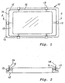
- Figures 1 and 2 show a gel cutter according to the invention 11th
- the gel cutter 11 is constructed as follows: one Base plate 12 has an elevation 13, the rectangular Forms side walls 14 with rounded corners 15. A tight fit to the outer surface of the side walls 14 is metal knife band 16 and with screws 17 fixed. The knife band 16 has a cutting edge 18, the Contour of a given contour corresponds to cutting / separating gel section 27.
- the gel cutout 27 is by pushing the Cutting edge 18 can be cut out / separated by the gel.
- the gel cutout 27 has a thickness that is much smaller than the circumference of the gel cutout is 27. As follows described, the scope of the gel cutout 27 is correct or at least approximately with the given scope Receiving point or chamber 24 in a gel holder 21.
- the knife band 16 can not only be made of metal, but also consist of glass, ceramic or plastic.
- a knife band made of glass or ceramic e.g. from several strip-shaped parts that are stacked at the ends are pushed to these parts on the outer wall 14 exactly to apply. These parts are e.g. four right angles angled strips, each at a corner of the elevation 13 are created and their legs overlap somewhat.
- the knife belt 16 can also be an integral part of the Survey 13 are trained. In this case, the Screws 17.
- the knife band 16 preferably has wedge-shaped Training at elevation 13 far end a sharp Cutting edge 18, which enables a clean cut. However, it may be sufficient for the knife band 16 to be sufficient running thin.
- the cutting edge 18 is preferably made of strips Elements formed on the outer surface 14 of the Elevation 13 are attached so tight that the Outer surface 14 of the survey 13 the cutting line Cutting edge 18 defined.
- FIG. 7 shows a cutting robot 41 in which a gel holder 21 is arranged.
- the gel holder 21 consists of Essentially consisting of a lower part 29 and an upper part 25.
- the lower part 29 consists of a frame 23 on which one Base plate 22 is attached, which is the bottom of the Bottom part 29 forms.
- the frame 23 and the base plate 22 delimit a chamber 24 in the lower part 29.
- the chamber 24 has a bottom surface, which for receiving a plate-shaped gel cutout 27 is formed. There are no firm connection between the bottom surface of the chamber 24 and the gel cutout 27.
- the base plate 22 of the lower part 29 is preferably made at least in part from a material suitable for a Radiation, especially light, is transparent, leading to electro-optical scanning or detection of Enrichment points can be used in a gel cutout 27 which is inserted in the gel holder 21. If one Radiation from below is not necessary Base plate 22 also opaque to light or energy even be reflective.
- the upper part 25 is designed as an attachment frame, the one Has clamping part 26, which on the lower part 29th the upper part 25 protrudes into the chamber 24 in such a way that a gel cutout 27 located in the chamber 24 on Edge between the clamping part 26 and the bottom surface of the Chamber 24 is clamped.
- the clamping part 26 is a bar which are essentially complementary to the contour of the chamber 24 is formed so that the clamping part 26 to the Sidewalls that define chamber 24, sliding or can be lowered into the chamber 24 with little play, so that the clamping action of the clamping part 26 is linear at the edge 28 of a gel cutout 27 arranged in the lower part 29 established.
- Fig. 4 shows a first embodiment in which the contour the chamber 24 exactly with the edge contour of the cutting edge 18th of the gel cutter 11 matches.
- a gel cutout 27, by means of the gel cutter 11 from a gel layer was cut out / separated, so fits with little Play in this chamber.
- Fig. 5 shows a second embodiment in which the contour the chamber 24 slightly larger than the edge contour of the Cutting edge 18 is.
- a gel cutout shows 27 a small undersize compared to the chamber 24 and can be arranged in the lower part 29 with a little play.
- the contour of the chamber is slightly smaller than the edge contour the cutting edge 18.
- the Gel cutout 27 a small excess compared to the chamber 24 and can be immovable in the lower part 29 without play order, so that no further measures to hold the Gel clipping are necessary.
- the top frame 25 is essentially one shaped like an angle strip and has a contour that exactly matches the Contour of the chamber in the lower part 29 is adjusted.
- the vertical leg or clamping part 26 of the upper part or Stacking frame 25 has a length that it when the top frame 25 rests on the lower part 29 on which Edge 28 of the gel rests and presses it in a little. By thereby on the edge 28 of the gel cutout 27 pressure is applied to the gel in the gel holder 21 kept immobile. This measure is particularly then displayed when the gel cutout versus dimensions of the frame 23 has a small undersize.
- the gel section is 27 with a thin layer of equilibration liquid 31 covered and the equilibrium liquid 31 also penetrates between the base plate 22 and the gel cutout 27 and between the frame 23 and the gel cutout 27 in one thin layer so that the gel cutout 27 completely is surrounded by equilibration liquid 31.
- This measure ensures that the gel has a constant degree of swelling and therefore has the same dimensions. For that is however, it is necessary for the gel clipping 27 to be scanned has been in the equilibration liquid 31 for a sufficiently long time, that there is a balance in the degree of swelling can. It is advantageous here, at least approximately constant temperature of the gel section 27 and the Comply with equilibration liquid 31.
- a second embodiment of the above basic procedure shows the edge contour of the Gel cutout 27 opposite the contour of the chamber 24 slight excess so that when the gel cutout 27 in the chamber 24 is used, it is immobile there is arranged.
- additional measures such as using the above mentioned clamping means 26 for fixing the position of the Gel cutout 27 in the gel holder 21 is not required.
- the Edge contour of the gel cutout 27 with respect to the contour of the Chamber 24 has a slight undersize, so that when the Gel cutout 27 is inserted into the chamber 24, he in a dimension in the gel holder 21 which is smaller than a predetermined, maximum permissible deviation between a piercing position in the gel cutout 27 and the The place of the cut is in a cut-out device.
- the gel cutout 27 is not only included Equilibrium liquid 31 covered, but is from this surround what the durability of the gel cutout 27 with unchanged spatial expansion improved. That too in in this case the position of the gel cutout 27 in the gel holder remains unchanged, is preferably by using the Ensured clamping means 26, which the edge region of the Gel cutout 27 slightly against the base plate of the Gel holder 21 presses.
- the Gel cutout 27 from the gel by means of a gel cutter 11 separated, the gel cutter 11 having a cutting edge 18 has a contour that approximates the contour of the Chamber 24 for receiving the gel cutout 27 in the gel holder 21 matches, with the expression "approximately” the exact Agreement, a slight undersize or a slight Are meant excessively.
- the Cut or separate the gel cutout 27 by placing it on of the gel cutter 11 performed on the gel.
- this is Gel preferably before separating the Gel cutout 27 stored in the equilibration liquid 31.
- the chamber 24 of the gel holder 21, which contains the gel cutout 27 contains at least as much equilibration liquid 31 given that there is a Equilibrium liquid layer that forms the whole Surface of the gel cutout 27 covers.
- a gel holder 21 according to the invention can be seen in use commercially available scanners, e.g. in Flatbed scanner. With appropriate execution of the Gel holder 21 can also be used in a specialized Scanners are used, e.g. with radioactive labeling the enrichment points in the gel section.
- the image generated by the scanner Gel section displayed on a screen, if necessary also in sections and greatly enlarged.
- An operator can use a cursor that advantageously the cutting geometry of the used Cutters replicates the on the screen Approach enrichment points, mark them graphically and to define or select the cut locations.
- a computer can be used the image information obtained with the scanner Concentration values and other characteristic data of the Determine enrichment points and on this basis Set piercing points.
- the gel holder 21 with the Gel cutout 27 after scanning for a long time, i.e. to the Example over eight or more hours, preferably in one appropriate wrapping and tempered to prevent loss to avoid equilibration liquid 31. This will avoided that the expansion of the gel cutout 27 changed over time and that the positions of the Move the enrichment points relative to the gel holder 21.
- the gel holder 21 is used for cutting out a cutting robot 41 placed.
- the cutting robot 41 has a drive that a cutting tool 51 the gel cutout 27 in the gel holder 21 at any position can drive.
- This drive can be manual or preferably be controlled by a computer in which the required tax data are stored or by a tax direction is delivered.
- this is Cutting tool 51 set up so that the end 83 of the Cookie cutter 66 in its rest position farthest from the Carrier 53 protrudes.
- the carrier As shown in FIGS. 8 and 9, there is 53 in the carrier an essentially oval, elongated cutout 55 the upper and lower arches 57, 58 each go Bore 61 or 62 to the upper or lower end face 63 or 64.
- the shape of the section 55 stems more from the Use a rotating milling cutter for the manufacture than on a technical need.
- the neckline can e.g. also have a rectangular cross section.
- the removal means is a cutter 66 through the holes 61, 62 longitudinally movable in the vertical direction (Z direction) to be led.
- the cutter 66 is a tube with an upper end Vacuum / positive pressure system is connected, the one under Contains liquid under or overpressure. In order to it is possible to create a vacuum in the cutter 66 generate to suck up material in its lower end. By blowing air or another gas it is Conversely possible, material sucked in from the cookie cutter 66 to drive down again. For an upgrade this material into the vacuum / positive pressure system avoid is in the cookie cutter 66 or in the one not shown Vacuum / overpressure system a flow limiter provided that is known per se.
- a spiral spring 68 surrounds the cutout 55 Cookie cutter 66.
- the spiral spring 68 is supported on the one hand the upper curvature 57 of the cutout 55 and the other a collar 71.
- the collar 71 is on suitable Type, e.g. by a clamping screw 72 on the cutter 66 attached.
- the coil spring 68 is dimensioned so that it is in Rest the collar 71 slightly against the lower one Curvature 58 of the cutout 55 presses on.
- the cutting tool 51 is suitably on one movable transport arm 78 (Fig. 7) of an X-Y-Z transport device so attached that the Cutting tool 51 is movable in the vertical direction the cutter 66 through the gel cutout 27 in the gel holder 21 lower and raise again.
- the structure and the function of an X-Y-Z transport device are on known and therefore not described here in detail.
- the movement of the Cutting tool 51 caused in the vertical direction that a gear (not shown) in the toothing of the Rack 76 engages, causing rotation of the gear the cutting tool 51 in one direction or the other raises or lowers.
- the cutting tool 51 can e.g. by means of screws which are inserted through holes 81, on a vertically movable carriage or the like be attached.
- the movement of the cutting tool 51 is also achievable by the carrier 53 laterally in rails is performed or by attaching the cutting tool 51 on a carriage which is connected to a drive.
- the cutting tool 51 can also be by means of a pneumatic actuator moved in the vertical direction become.
- the cutting tool 51 is Cutter robot 41 by moving the arm 78 in the X direction and the carrier 77 of the cutting tool 51 on the arm 78 in the Y direction to a predetermined piercing position method.
- the cutting tool 51 is down in the Z direction lowered.
- the lower end of the cutter 66 hits first on a layer of equilibration liquid.
- At the further lowering is advantageously ensured that first a short column of equilibration liquid 31 gets into the cutter 66.
- either Pressure equalization can take place with the environment, or it can even by detecting the impact of the cutter 66 on the Surface of the equilibration liquid 31 or at Falling below a certain level slightly negative pressure Cookie cutter 66 can be created.
- the cutter 66 e.g. a hollow metal needle and is thus electrically conductive
- the detection of the Impact of the cutter 66 on the Equilibration liquid 31 for example by detection the occurrence of an electrical contact between the Cookie cutter 66 and the equilibration liquid 31 by means of an electronic circuit.
- the lower end 83 of the Cookie cutter 66 When lowering further, the lower end 83 of the Cookie cutter 66 finally the gel cutout 27, with a Gel piece 69 is pushed into the cutter 66. Finally, the lower end 83 abuts the base plate 22 on. Since the cutter 66 in the carrier 53 in the longitudinal direction is movable, it is not necessary to move the Cutting tool 51 in the Z direction exactly when it hits to stop on the base plate 22. This is beneficial because it does not mean that the Cutter 66 on a solid obstacle (the base plate 22) to detect or the difference between the resistance penetrating the gel cutout 27 and the resistance to take into account when hitting the base plate 22.
- the cutting robot 41 runs over the cutting tool 51 the storage vessels, e.g. over the cavities (wells) from a microtiter plate 91 (see FIG. 7) it over one of the vessels and pushes the contents of the Cookie cutter 66 by applying positive pressure down into it provided vessel. This is the cutting tool flushed through the equilibration liquid 31 so that a special rinsing process or the use of a Cookie cutters with disposable cutters are not necessary.
- Equilibration liquid 31 is removed from the gel holder, according to the invention, equilibration liquid 31 in sufficient volume in the gel holder 21 to to make sure the gel clipping is from a sufficient amount of equilibration liquid remains surrounded.
- Another advantage of the invention is that in no ambient air is sucked into the cutter 66 and not in one of the vessels, e.g. into the cavities the microtiter plate 91 is transferred.
- the gel cutout 27 in the gel holder 21 preferably arranged so that it in the Equilibration liquid 31 floats and is therefore from the bottom of the gel holder 21 spaced.
- To detach one Gel piece 69 from the gel cutout 27 is therefore sufficient Piercing a cutter 51.
- Da Equilibration liquid 31 also below the gel section 27 is present when the gel cutout is cut out 27 by applying a vacuum in the cutter 66 first some equilibrium liquid is sucked in, then a Gel piece 69 cut out, then something else Equilibration liquid drawn in.
- the column of post-absorbed equilibration liquid 31 is placed a separation of the recorded gel piece 69 from the Surrounding area. Above a cut-out gel piece 69 there is also a small column Equilibration liquid 31, so that the gel piece also in this direction is shielded from the environment.
- the Places on the gel cutout 27 where the pieces of gel to be separated Before the gel pieces 69 are separated, the Places on the gel cutout 27 where the pieces of gel to be separated.
- the removal device 51 is to the predetermined locations on the gel cutout 27 is positioned and then the gel pieces 69 are separated performed by means of the cutting tool 51.
- a separated piece of gel 69 becomes the cutter 66 preferably by creating overpressure in the cutter 66 pushed out.
- the one Includes lower part 29 and an upper part 25, the Lower part has a chamber 24 which has a bottom surface and for receiving a plate-shaped gel cutout 27 is formed, and the upper part 25 is a clamping part 26 has that with the upper part placed on the lower part 29 25 protrudes into the chamber 24 such that one in the Chamber 24 located gel cutout 27 on the edge between the clamping part 26 and the bottom surface of the chamber 24 is jammed.
- the gel holder (21) the gel cutout (27) in the equilibration liquid embedded.
- the means of establishing contact between the Gel section 27 and the equilibration liquid 31 are at the top described in the description of the gel holder 21.
- the Removal device 51 with a device for generating of negative pressure and positive pressure in the cutter 66, so that due to negative pressure in the cutter 66 by the Cookie cutter separated gel piece 69 into the cutter 66 can be sucked in and after the gel piece 69 another one Amount of the equilibration liquid 31 that the gel piece 69 surrounds, can be sucked up, and by generating an overpressure in the cookie cutter 66, the one taken with the cookie cutter Material, especially the gel piece 69, again from the Cookie cutter 66 is ejectable.
- the gel holder comprises 21 a lower part 29 and an upper part 25, the lower part has a chamber 24 which has a bottom surface and for Recording a plate-shaped gel cutout 27 is formed, and the upper part 25 is a clamping part 26 has that with the upper part placed on the lower part 29 25 protrudes into the chamber 24 such that one in the Chamber 24 located gel cutout 27 on the edge between the clamping part 26 and the bottom surface of the chamber 24 is jammed.
Landscapes
- Health & Medical Sciences (AREA)
- Life Sciences & Earth Sciences (AREA)
- Molecular Biology (AREA)
- Chemical & Material Sciences (AREA)
- Chemical Kinetics & Catalysis (AREA)
- Electrochemistry (AREA)
- Physics & Mathematics (AREA)
- Analytical Chemistry (AREA)
- Biochemistry (AREA)
- General Health & Medical Sciences (AREA)
- General Physics & Mathematics (AREA)
- Immunology (AREA)
- Pathology (AREA)
- Sampling And Sample Adjustment (AREA)
Abstract
Description
In einem ersten Schritt werden die Anreicherungspunkte durch Einfärben markiert. Anschliessend werden nach Vorgabe des Benutzers die auszuschneidenden Gelstücke mittels eines Computers elektronisch erfasst. Danach wird die Gelplatte in einen Ausstechroboter (so genannten "Gelpicker") überführt, der die im ersten Schritt definierten Gelstücke heraussticht und in Probegefässe, z.B. die Kavitäten (wells) einer Mikrotiterplatte überführt. Wegen der Fixierung des Gels auf dem Träger kann dabei zwischen dem ersten Schritt, dem Einfarben, und dem zweiten Schritt, dem Ausstechen, eine beträchtliche Zeitspanne vergehen, ohne dass merkliche Abweichungen der Positionen der auszuschneidenden Gelstücke auftreten und das beabsichtigte Ausstechen der Gelstücke beeinträchtigen, welche die Anreicherungspunkte enthalten.
- Fig. 1
- eine Draufsicht eines Gelschneiders 11,
- Fig. 2
- einen Querschnitt des Gelschneiders 11 gemäss Linie A-A in Fig. 1,
- Fig. 3
- eine Draufsicht eines Gelauschnitts 27,
- Fig. 4
- einen Querschnitt der Bestandsteile eines Gelhalters 21,
- Fig. 5
- einen Querschnitt durch den Gelhalter 21 gemäss Fig. 4 mit einem darin angeordneten Gelauschnitt 27,
- Fig. 6
- einen Querschnitt durch den Gelhalter 21 gemäss Fig. 4 mit einem etwas kleineren Gelauschnitt als in Fig. 5;
- Fig. 7
- eine perspektivische Ansicht eines Ausstechroboters 41,
- Fig. 8
- eine perspektivische Ansicht eines Ausstechwerkzeugs 51,
- Fig. 9
- eine Explosionsdarstellung des Ausstechwerkzeugs 51 in Fig. 8.
| Bezugszeichenliste | |
| 11 | Gelschneider |
| 12 | Grundplatte |
| 13 | Erhebung |
| 14 | Seitenwand |
| 15 | Ecken |
| 16 | Messerband |
| 17 | Schrauben |
| 18 | Schneidekante des Gelschneiders 11 |
| 19 | |
| 20 | |
| 21 | Gelhalter |
| 22 | Grundplatte |
| 23 | Rahmen |
| 24 | Kammer zur Aufnahme des Gelausschnitts |
| 25 | Aufsatzrahmen / Oberteil des Gelhalters 21 |
| 26 | Schenkel /Klemmteil des Aufsatzrahmens 25 |
| 27 | Gelausschnitt |
| 28 | Rand des Gelausschnitts |
| 29 | Unterteil |
| 30 | |
| 31 | Äquilibrierflüssigkeit |
| 41 | Ausstechroboter |
| 51 | Ausstechwerkzeug/Entnahmeeinrichtung |
| 53 | Träger |
| 55 | Ausschnitt |
| 57 | Wölbung |
| 58 | Wölbung |
| 61 | Bohrung |
| 62 | Bohrung |
| 63 | Stirnfläche |
| 64 | Stirnfläche |
| 65 | Flüssigkeit im Ausstecher 66 |
| 66 | Ausstecher/Entnahmemittel |
| 68 | Spiralfeder |
| 69 | Gelstück |
| 71 | Stellring |
| 72 | Klemmschraube |
| 74 | Nut |
| 76 | Zahnleiste |
| 77 | Träger des Ausstechwerkzeugs 51 |
| 78 | Transportarm |
| 79 | ein ausgestossenes Gelstück |
| 81 | Löcher |
| 82 | oberes Ende des Ausstechers 66 |
| 83 | unteres Ende des Ausstechers 66 |
| 91 | Mikrotiterplatte |
Durch Anfärben der aufgetrennten Proben werden die Proteine sichtbar gemacht und deren Lage in der Gelschicht durch Absorption, Fluoreszenz, Radioaktivität oder Lumineszenz auf dem Gel ermittelt bzw. erfasst. Je nach Färbe- oder Markierungsmethode wird dafür ein entsprechendes Lesegerät z.B. einen Scanner verwendet, um die Lage der Anreicherungspunkte in digitaler Form zur weiteren Verarbeitung ermitteln bzw. erfassen zu können. Die digitalen Daten werden in einer Datenbank abgelegt und können von weiteren Programmen, z.B. für die Steuerung eines Ausstechroboters, benutzt werden. Programme dieser Art sind auf dem Markt erhältlich.
Claims (25)
- Verfahren zum Positionieren eines Gels in einem Gelhalter, dadurch gekennzeichnet, dass(a) aus dem Gel ein Gelausschnitt (27) mit einer Randkontur abgetrennt wird, die genau oder wenigstens annähernd mit der Kontur einer Kammer (24) zur Aufnahme des Gelausschnitts (27) in einem Gelhalter (21) übereinstimmt,(b) der Gelausschnitt (27) in die Kammer (24) des Gelhalters (21) eingesetzt wird, und(c) der Gelausschnitt (27) mit einer Äquilibrierflüssigkeit (31) gedeckt wird.
- Verfahren gemäss Anspruch 1, dadurch gekennzeichnet, dass die Randkontur des Gelausschnitts (27) gegenüber der Kontur der Kammer (24) ein geringes Untermass aufweist, so dass, wenn der Gelausschnitt (27) in die Kammer (24) eingesetzt wird, er in einem Mass im Gelhalter (21) beweglich ist, das kleiner als eine vorgegebene maximal zulässige Abweichung zwischen einer Ausstechposition im Gelausschnitt (27) und dem Ausstechort in einer Ausstecheinrichtung ist.
- Verfahren gemäss Anspruch 1, dadurch gekennzeichnet, dass die Randkontur des Gelausschnitts (27) gegenüber der Kontur der Kammer (24) ein geringes Übermass aufweist, so dass, wenn der Gelausschnitt (27) in die Kammer (24) eingesetzt wird, er dort unbeweglich angeordnet ist.
- Verfahren gemäss einem der Ansprüche 1 bis 3, dadurch gekennzeichnet, dass die Lage des Gelausschnitts (27) in Bezug auf die Kammer (24) mittels eines Klemmmittels (25) fixiert wird.
- Verfahren gemäss einem der Ansprüche 1 bis 4, dadurch gekennzeichnet, dass der Gelausschnitt (27) mittels eines Gelschneiders (11) aus dem Gel abgetrennt wird, wobei der Gelschneider (11) eine Schneidkante (18) mit einer Kontur aufweist, die annähernd mit der Kontur der Kammer (24) zur Aufnahme des Gelausschnitts (27) im Gelhalter (21) übereinstimmt.
- Verfahren gemäss Anspruch 5, dadurch gekennzeichnet, dass das Abtrennen des Gelausschnitts (27) aus dem Gel durch Auflegen des Gelschneiders (11) auf das Gel durchgeführt wird.
- Verfahren gemäss einem der Ansprüche 1 bis 6, wobei das Gel bereits vor dem Schneiden des Gelausschnitts (27) in der Äquilibrierflüssigkeit (31) gelagert wird.
- Verfahren gemäss einem der Ansprüche 1 bis 7, wobei in der Kammer (24) des Gelhalters (21), welcher den Gelausschnitt (27) enthält, mindestens soviel Äquilibrierflüssigkeit (31) gegeben wird, dass sich über dem Gelausschnitt (27) eine Äquilibrierflüssigkeit-Schicht ausbildet, welche die ganze Oberfläche des Gelausschnitts (27) deckt.
- Gelhalter zur Durchführung des Verfahrens gemäss einem der Ansprüche 1 bis 8, dadurch gekennzeichnet, dass er ein Unterteil (29) und ein rahmenförmiges Oberteil (25) umfasst, wobei das Unterteil (29) eine Kammer (24) mit einer Bodenfläche aufweist, welche zur Aufnahme eines plattenförmigen Gelausschnittes (27) ausgebildet ist, und das Oberteil (25) ein Klemmteil (26) aufweist, das bei auf dem Unterteil (29) aufgesetztem Oberteil (25) in die Kammer (24) derart hineinragt, dass ein in der Kammer (24) befindlicher Gelausschnitt (27) am Rande zwischen dem Klemmteil (26) und der Bodenfläche der Kammer (24) eingeklemmt ist.
- Gelhalter gemäss Anspruch 9, dadurch gekennzeichnet, dass das Unterteil (29) einen Boden aufweist, der wenigstens zum Teil aus einem Material besteht, das für eine Strahlung, insbesondere Licht, transparent ist, die zur Detektion von Anreicherungspunkten in einem Gelausschnitt (27), der im Gelhalter (21) eingelegt ist, verwendbar ist.
- Gelhalter gemäss Anspruch 9 oder 10, dadurch gekennzeichnet, dass das Klemmteil (26) eine Leiste ist, die im Wesentlichen komplementär zur Kontur der Kammer (24) ausgebildet ist, so dass das Klemmteil (26) an den Seitenwänden, welche die Kammer (24) begrenzen, gleitend oder mit geringem Spiel in die Kammer (24) absenkbar ist, so dass sich die Klemmwirkung des Klemmteils (26) linienförmig am Rand (28) eines im Unterteil (29) angeordneten Gelausschnittes (27) einstellt.
- Gelschneider zur Durchführung des Verfahrens gemäss einem der Ansprüche 1 bis 8, dadurch gekennzeichnet, dass er eine Schneidekante (18) aufweist, deren Kontur einer vorgegebenen Kontur eines aus dem Gel abzutrennenden Gelausschnitts (27) entspricht, so dass der Gelausschnitt (27) durch Hindurchdrücken der Schneidkante (18) durch das Gel herausschneidbar ist, wobei der Gelausschnitt (27) eine Dicke hat, die viel kleiner als der Umfang des Gelausschnitts (27) ist, und der Umfang des Gelausschnitts (27) genau oder wenigstens annähernd mit dem vorgegebenen Umfang einer Aufnahmestelle in einem Gelhalter übereinstimmt.
- Gelschneider gemäss Anspruch 12, dadurch gekennzeichnet, dass die Schneidkante (18) als eine scharfe Kante eines Bandes (16) oder einer Umrandung aus mindestens zwei streifenförmigen Elementen ausgebildet ist, die an der Aussenfläche (14) einer Erhebung (13) eng anliegend angebracht sind, wobei die Aussenfläche (14) der Erhebung (13) die Schneidelinie der Schneidkante (18) definiert.
- Gelschneider gemäss Anspruch 13, wobei das Band (16) bzw. die streifenförmigen Elemente aus Metall, Keramik, Glas oder Kunststoff bestehen.
- Verfahren zum Abtrennen und Entfernen von Gelstücken aus einem Gelausschnitt (27), der sich zusammen mit einer Äquilibrierflüssigkeit (31) in einem Gelhalter (21) befindet,
dadurch gekennzeichnet, dass(a) sich oberhalb als auch unterhalb des Gelausschnitts (27) zumindest im Bereich der zu entfernenden Stücke eine Schicht Äquilibrierflüssigkeit (31) befindet,(b) ein rohrförmiges Entnahmemittel (66) mit seinem eine Öffnung aufweisenden Ende (83) durch den Gelausschnitt (27) hindurchgestossen wird, wodurch ein Gelstück (69) ausgestochen wird, und danach durch Erzeugen von Unterdruck im Entnahmemittel (66) das ausgestochene Gelstück (69) und nachfolgende Äquilibrierflüssigkeit (31) in das Entnahmemittel (66) eingesaugt wird, so dass das Gelstück (69) von der Öffnung (83) des Entnahmemittels (66) durch eine Säule der Äquilibrierflüssigkeit (31) getrennt ist. - Verfahren gemäss Anspruch 15, dadurch gekennzeichnet, dass sich über dem Gelausschnitt (27) eine Schicht der Äquilibrierflüssigkeit (31) befindet, so dass beim Durchstossen des Entnahmemittels (66) durch den Gelausschnitt (27) zunächst eine kurze Flüssigkeitssäule der Äquilibrierflüssigkeit (31) in dem Entnahmemittel (66) aufgenommen wird, wodurch nach dem Abtrennen eines Gelstückes (69) auch oberhalb des Gelstückes (69) im Entnahmemittel (66) eine Schicht der Äquilibrierflüssigkeit (31) vorhanden ist.
- Verfahren gemäss Anspruch 15 oder 16, dadurch gekennzeichnet, dass vor dem Abtrennen der Gelstücke (69) die Orte auf dem Gelausschnitt(27) festgelegt werden, wo die abzutrennenden Gelstücke (69) liegen, der Gelhalter (21) in eine Entnahmevorrichtung mit mindestens einer Entnahmeeinrichtung (51) mit einem Entnahmemittel (66) eingesetzt wird und die Entnahmeeinrichtung (51) an die vorbestimmten Orte auf dem Gelausschnitt (27) positioniert und dann das Abtrennen der Gelstücke (69) mittels der Entnahmeeinrichtung (51) durchgeführt wird.
- Verfahren gemäss einem der Ansprüche 15 bis 17, dadurch gekennzeichnet, dass ein abgetrenntes Gelstück (69) aus dem Entnahmemittel (66) durch Erzeugen von Überdruck im Entnahmemittel (66) ausgestossen wird.
- Verfahren gemäss einem der Ansprüche 15 bis 18, dadurch gekennzeichnet, dass der Gelhalter (21) ein Unterteil (29) und ein Oberteil (25) umfasst, wobei das Unterteil eine Kammer (24) mit einer Bodenfläche aufweist, welche zur Aufnahme eines plattenförmigen Gelausschnittes (27) ausgebildet ist, und das Oberteil (25) ein Klemmteil (26) aufweist, das bei auf dem Unterteil (29) aufgesetztem Oberteil (25) in die Kammer (24) derart hineinragt, dass ein in der Kammer (24) befindlicher Gelausschnitt (27) am Rande zwischen dem Klemmteil (26) und der Bodenfläche der Kammer (24) eingeklemmt ist.
- Entnahmeeinrichtung zum Abtrennen und Entfernen eines Gelstückes (69) aus einem Gelausschnitt (27) zur Durchführung des Verfahrens gemäss einem der Ansprüche 15 bis 19, dadurch gekennzeichnet, dass sie folgende Komponenten enthält:(a) ein im Wesentlichen rohrförmiges Entnahmemittel (66), das in einem Träger (53) längsbeweglich angeordnet ist und dessen eines dem Abtrennen dienenden Ende (83) als Ausstechmittel ausgebildet ist, und(b) eine Feder (68), die sich am Träger (53) und am Entnahmemittel (66) derart abstützt, dass das Entnahmemittel (66) gegen die Rückstellkraft der Feder (68) aus seiner Ruhelage herausbewegbar ist.
- Entnahmeeinrichtung gemäss Anspruch 20, dadurch gekennzeichnet, dass das Ende (83) des Entnahmemittels (66) in dessen Ruhelage am Weitesten aus dem Träger (53) vorsteht.
- Vorrichtung zum Analysieren vorbestimmter Bereiche eines Gelausschnittes, insbesondere von Anreicherungspunkten nach Durchführen einer Gemischtrennung in einem Gel,
dadurch gekennzeichnet, dass sie folgende Komponenten umfasst:über die ausgewählten zu entnehmenden Bereiche des Gelausschnittes (27) im Gelhalter (21) zu positionieren und sie zum Gelausschnitt (27) hin zu bewegen, so dass Entnahmemittel (66) jeweils an einem vorgegebenen Ort durch den Gelausschnitt (27) hindurchgetrieben werden kann, um ein Gelstück (69) aufzunehmen.(a) eine erste Vorrichtung, in welche einen Gelhalter (21) zur Aufnahme eines Gelausschnittes (27) einsetzbar ist und welche über Mittel verfügt, um die zu analysierenden Bereiche des Gelausschnittes (27) zu detektieren und/oder eine Darstellung des Gelausschnittes (27) zu erstellen, in der die für die Analyse in Frage kommende Bereiche erkennbar sind, wobei die erste Vorrichtung Mittel zum Markieren der zu analysierenden Bereiche auf einer elektronisch erzeugten Abbildung des Gelausschnittes (27) enthält, und wobei im Gelhalter (21) das Gelausschnitt (27) in Kontakt mit einer Äquilibrierflüssigkeit (31) ist; und(b) eine zweite Vorrichtung, welche zum Abtrennen und Entfernen eines Stückes (69) aus einem Gelausschnitt (27) dient, mit einer Aufnahmestelle für den Gelhalter (21) und mit Transportmitteln, um eine Entnahmeeinrichtung (51), welche zum Abtrennen und Entfernen eines Stückes (69) aus einem Gelausschnitt (27) dient, - Vorrichtung gemäss Anspruch 22, dadurch gekennzeichnet, dass, die Entnahmemittel (66) mit einer Vorrichtung zum Erzeugen von Unterdruck und Überdruck verbunden ist, so dass durch Unterdruck im Entnahmemittel (66) ein durch das Entnahmemittel (66) abgetrenntes Gelstück (69) in das Entnahmemittel (66) einsaugbar und nach dem Gelstück (69) noch eine bestimmte Menge Äquilibrierflüssigkeit (31), die das Gelstück (69) umgibt, nachsaugbar ist, und durch Erzeugen eines Überdrucks im Entnahmemittel (66) das mit dem Entnahmemittel (66) aufgenommene Material, insbesondere das Gelstück (69), wieder aus dem Entnahmemittel (66) ausstossbar ist.
- Vorrichtung gemäss Anspruch 22 oder 23, dadurch gekennzeichnet, dass, der Gelhalter (21) ein Unterteil (29) und ein Oberteil (25) umfasst, wobei das Unterteil (29) eine Kammer (24) aufweist, die eine Bodenfläche hat und zur Aufnahme eines plattenförmigen Gelausschnittes (27) ausgebildet ist, und das Oberteil (25) ein Klemmteil (26) aufweist, das bei auf dem Unterteil (29) aufgesetztem Oberteil (25) in die Kammer (24) derart hineinragt, dass ein in der Kammer (24) befindlicher Gelausschnitt (27) am Rande zwischen dem Klemmteil (26) und der Bodenfläche der Kammer (24) eingeklemmt ist.
- Vorrichtung gemäss einem der Ansprüche 22 bis 24, dadurch gekennzeichnet, dass, die zweite Vorrichtung (51) folgende Komponenten enthält:(a) ein im Wesentlichen rohrförmiges Entnahmemittel (66) , das in einem Träger (53) längsbeweglich angeordnet ist und dessen eines dem Abtrennen dienenden Ende (83) als Ausstechmittel ausgebildet ist, und(b) eine Feder (68), die sich am Träger (53) und am Entnahmemittel (66) derart abstützt, dass das Entnahmemittel (66) gegen die Rückstellkraft der Feder (68) aus seiner Ruhelage herausbewegbar ist.
Priority Applications (1)
| Application Number | Priority Date | Filing Date | Title |
|---|---|---|---|
| EP03076933A EP1384994A1 (de) | 2002-07-23 | 2003-06-23 | Verfahren und Vorrichtung zum Lokalisieren und Ausschneiden von Anreicherungen in einem Gel |
Applications Claiming Priority (3)
| Application Number | Priority Date | Filing Date | Title |
|---|---|---|---|
| EP02078009A EP1384993A1 (de) | 2002-07-23 | 2002-07-23 | Verfahren und Vorrichtung zum Lokalisieren und Ausschneiden von Anreicherungen in einem Gel |
| EP02078009 | 2002-07-23 | ||
| EP03076933A EP1384994A1 (de) | 2002-07-23 | 2003-06-23 | Verfahren und Vorrichtung zum Lokalisieren und Ausschneiden von Anreicherungen in einem Gel |
Publications (1)
| Publication Number | Publication Date |
|---|---|
| EP1384994A1 true EP1384994A1 (de) | 2004-01-28 |
Family
ID=30001864
Family Applications (1)
| Application Number | Title | Priority Date | Filing Date |
|---|---|---|---|
| EP03076933A Withdrawn EP1384994A1 (de) | 2002-07-23 | 2003-06-23 | Verfahren und Vorrichtung zum Lokalisieren und Ausschneiden von Anreicherungen in einem Gel |
Country Status (1)
| Country | Link |
|---|---|
| EP (1) | EP1384994A1 (de) |
Citations (4)
| Publication number | Priority date | Publication date | Assignee | Title |
|---|---|---|---|---|
| EP0505929A2 (de) * | 1991-03-29 | 1992-09-30 | Shimadzu Corporation | Vorrichtung für zweidimensionale Elektrophorese |
| WO1998023950A1 (en) * | 1996-11-29 | 1998-06-04 | Oxford Glycosciences (Uk) Ltd. | Gels, methods and apparatus for identification and characterization of biomolecules |
| US5938906A (en) * | 1997-04-04 | 1999-08-17 | C.C. Imex | Horizontal gel electrophoresis casting cassette |
| WO2001050121A2 (en) * | 2000-01-06 | 2001-07-12 | Carnegie Mellon University | Cutting tool for multiple sample retrieval from gelatinous material |
-
2003
- 2003-06-23 EP EP03076933A patent/EP1384994A1/de not_active Withdrawn
Patent Citations (4)
| Publication number | Priority date | Publication date | Assignee | Title |
|---|---|---|---|---|
| EP0505929A2 (de) * | 1991-03-29 | 1992-09-30 | Shimadzu Corporation | Vorrichtung für zweidimensionale Elektrophorese |
| WO1998023950A1 (en) * | 1996-11-29 | 1998-06-04 | Oxford Glycosciences (Uk) Ltd. | Gels, methods and apparatus for identification and characterization of biomolecules |
| US5938906A (en) * | 1997-04-04 | 1999-08-17 | C.C. Imex | Horizontal gel electrophoresis casting cassette |
| WO2001050121A2 (en) * | 2000-01-06 | 2001-07-12 | Carnegie Mellon University | Cutting tool for multiple sample retrieval from gelatinous material |
Similar Documents
| Publication | Publication Date | Title |
|---|---|---|
| DE60316562T2 (de) | Gewebe-array-konstruktions-instrument | |
| DE69636571T2 (de) | Testkarte für Analysen | |
| EP0292899B1 (de) | Verfahren zur Mikroinjektion in Zellen bzw. zum Absaugen aus einzelnen Zellen oder ganzer Zellen aus Zellkulturen | |
| DE2145023C3 (de) | ||
| DE2143664C3 (de) | Telleranordnung mit einem Zentrifugenteller und einem Probenteller | |
| EP3705889B1 (de) | Eieruntersuchungseinrichtung | |
| DE2055948A1 (de) | Verfahren und Vorrichtung zur Über tragung von Flussigkeitsproben | |
| EP2027447B1 (de) | Vorrichtung und verfahren zur automatisierten reproduzierbaren herstellung von auf objektträgern angeordneten zu untersuchenden zell- oder gewebeproben | |
| DE2140555B2 (de) | ||
| EP1606606B1 (de) | Gewebebestanzvorrichtung | |
| EP1247085B1 (de) | Verfahren zur herstellung von materialblöcken mit einer vielzahl von zu untersuchenden proben | |
| EP1384993A1 (de) | Verfahren und Vorrichtung zum Lokalisieren und Ausschneiden von Anreicherungen in einem Gel | |
| AT412238B (de) | Verfahren und vorrichtung zur manipulation mit proben | |
| EP0935773B1 (de) | Anlage für den einschluss von histologischen und biologischen proben | |
| DE102018200923B4 (de) | Verfahren zum sequentiellen Untersuchen einer Mehrzahl von Proben, Probenträgereinheit und Aufnahmeeinheit für Lichtblattebenenmikroskopie | |
| DE102019120201B3 (de) | Anordnung mit Objektplatte und transparentem Markierungsrahmen | |
| WO2004025273A1 (de) | Vorrichtung und verfahren zur durchführung von immunologischen markierungstechniken für gewebedünnschnitte | |
| EP1556476A2 (de) | Verfahren und vorrichtung zur manipulation mit proben | |
| DE102023103097A1 (de) | Vorrichtung zum Erkennen von Nukleinsäuren durch thermostatische Amplifikation mit kolloidalem Gold | |
| EP1352227B1 (de) | Glasschneidegerät für objektträger | |
| WO1991017832A1 (de) | Objektträger für nasse oder feuchte präparate, z.b. blut | |
| EP0247340A1 (de) | Verfahren und Vorrichtung zur Isolierung von Fraktionen von Makromolekülen aus Dichtegradienten | |
| DE10119461C2 (de) | Verfahren und Vorrichtung zum Heraustrennen von Analysematerial aus einem Holzbohrkern | |
| EP4366633B1 (de) | Verfahren, vorrichtung und system zur entfernung des chorions eines nicht-menschlichen embryos | |
| DE102005042262B3 (de) | Vorrichtung zur Bearbeitung schneidfähiger Proben |
Legal Events
| Date | Code | Title | Description |
|---|---|---|---|
| PUAI | Public reference made under article 153(3) epc to a published international application that has entered the european phase |
Free format text: ORIGINAL CODE: 0009012 |
|
| AK | Designated contracting states |
Kind code of ref document: A1 Designated state(s): AT BE BG CH CY CZ DE DK EE ES FI FR GB GR HU IE IT LI LU MC NL PT RO SE SI SK TR |
|
| AX | Request for extension of the european patent |
Extension state: AL LT LV MK |
|
| 17P | Request for examination filed |
Effective date: 20040214 |
|
| AKX | Designation fees paid |
Designated state(s): AT BE BG CH CY CZ DE DK EE ES FI FR GB GR HU IE IT LI LU MC NL PT RO SE SI SK TR |
|
| STAA | Information on the status of an ep patent application or granted ep patent |
Free format text: STATUS: THE APPLICATION IS DEEMED TO BE WITHDRAWN |
|
| 18D | Application deemed to be withdrawn |
Effective date: 20110104 |