EP1384967A2 - Fuel cell cooling system - Google Patents
Fuel cell cooling system Download PDFInfo
- Publication number
- EP1384967A2 EP1384967A2 EP03015150A EP03015150A EP1384967A2 EP 1384967 A2 EP1384967 A2 EP 1384967A2 EP 03015150 A EP03015150 A EP 03015150A EP 03015150 A EP03015150 A EP 03015150A EP 1384967 A2 EP1384967 A2 EP 1384967A2
- Authority
- EP
- European Patent Office
- Prior art keywords
- water
- cooling system
- exhaust water
- unit
- coolant
- Prior art date
- Legal status (The legal status is an assumption and is not a legal conclusion. Google has not performed a legal analysis and makes no representation as to the accuracy of the status listed.)
- Withdrawn
Links
Images

Classifications
-
- H—ELECTRICITY
- H01—ELECTRIC ELEMENTS
- H01M—PROCESSES OR MEANS, e.g. BATTERIES, FOR THE DIRECT CONVERSION OF CHEMICAL ENERGY INTO ELECTRICAL ENERGY
- H01M8/00—Fuel cells; Manufacture thereof
- H01M8/04—Auxiliary arrangements, e.g. for control of pressure or for circulation of fluids
- H01M8/04007—Auxiliary arrangements, e.g. for control of pressure or for circulation of fluids related to heat exchange
-
- F—MECHANICAL ENGINEERING; LIGHTING; HEATING; WEAPONS; BLASTING
- F28—HEAT EXCHANGE IN GENERAL
- F28C—HEAT-EXCHANGE APPARATUS, NOT PROVIDED FOR IN ANOTHER SUBCLASS, IN WHICH THE HEAT-EXCHANGE MEDIA COME INTO DIRECT CONTACT WITHOUT CHEMICAL INTERACTION
- F28C3/00—Other direct-contact heat-exchange apparatus
- F28C3/06—Other direct-contact heat-exchange apparatus the heat-exchange media being a liquid and a gas or vapour
- F28C3/08—Other direct-contact heat-exchange apparatus the heat-exchange media being a liquid and a gas or vapour with change of state, e.g. absorption, evaporation, condensation
-
- F—MECHANICAL ENGINEERING; LIGHTING; HEATING; WEAPONS; BLASTING
- F28—HEAT EXCHANGE IN GENERAL
- F28D—HEAT-EXCHANGE APPARATUS, NOT PROVIDED FOR IN ANOTHER SUBCLASS, IN WHICH THE HEAT-EXCHANGE MEDIA DO NOT COME INTO DIRECT CONTACT
- F28D5/00—Heat-exchange apparatus having stationary conduit assemblies for one heat-exchange medium only, the media being in contact with different sides of the conduit wall, using the cooling effect of natural or forced evaporation
- F28D5/02—Heat-exchange apparatus having stationary conduit assemblies for one heat-exchange medium only, the media being in contact with different sides of the conduit wall, using the cooling effect of natural or forced evaporation in which the evaporating medium flows in a continuous film or trickles freely over the conduits
-
- H—ELECTRICITY
- H01—ELECTRIC ELEMENTS
- H01M—PROCESSES OR MEANS, e.g. BATTERIES, FOR THE DIRECT CONVERSION OF CHEMICAL ENERGY INTO ELECTRICAL ENERGY
- H01M8/00—Fuel cells; Manufacture thereof
- H01M8/04—Auxiliary arrangements, e.g. for control of pressure or for circulation of fluids
- H01M8/04007—Auxiliary arrangements, e.g. for control of pressure or for circulation of fluids related to heat exchange
- H01M8/04029—Heat exchange using liquids
-
- H—ELECTRICITY
- H01—ELECTRIC ELEMENTS
- H01M—PROCESSES OR MEANS, e.g. BATTERIES, FOR THE DIRECT CONVERSION OF CHEMICAL ENERGY INTO ELECTRICAL ENERGY
- H01M8/00—Fuel cells; Manufacture thereof
- H01M8/04—Auxiliary arrangements, e.g. for control of pressure or for circulation of fluids
- H01M8/04082—Arrangements for control of reactant parameters, e.g. pressure or concentration
- H01M8/04089—Arrangements for control of reactant parameters, e.g. pressure or concentration of gaseous reactants
- H01M8/04119—Arrangements for control of reactant parameters, e.g. pressure or concentration of gaseous reactants with simultaneous supply or evacuation of electrolyte; Humidifying or dehumidifying
-
- Y—GENERAL TAGGING OF NEW TECHNOLOGICAL DEVELOPMENTS; GENERAL TAGGING OF CROSS-SECTIONAL TECHNOLOGIES SPANNING OVER SEVERAL SECTIONS OF THE IPC; TECHNICAL SUBJECTS COVERED BY FORMER USPC CROSS-REFERENCE ART COLLECTIONS [XRACs] AND DIGESTS
- Y02—TECHNOLOGIES OR APPLICATIONS FOR MITIGATION OR ADAPTATION AGAINST CLIMATE CHANGE
- Y02E—REDUCTION OF GREENHOUSE GAS [GHG] EMISSIONS, RELATED TO ENERGY GENERATION, TRANSMISSION OR DISTRIBUTION
- Y02E60/00—Enabling technologies; Technologies with a potential or indirect contribution to GHG emissions mitigation
- Y02E60/30—Hydrogen technology
- Y02E60/50—Fuel cells
Definitions
- the present invention relates to a cooling system for a fuel cell module.
- PEM fuel cell The most advanced type of fuel cell, both technically and commercially, is the proton exchange membrane or PEM fuel cell.
- Current PEM type fuel cells operate at temperatures of around 80 °C, which is a lower temperature than the operation temperature of some other types of fuel cells. Because the exhaust does not carry away significant heat, heat rejected to the coolant is relatively high compared to internal combustion engines. This, combined with the relatively low operating temperatures, makes it difficult to cool fuel cell systems.
- a fuel cell cooling system may require large bulky heat exchangers and may require a cooling fan which consumes large amounts of power. Also hot liquid discharged from fuel cells may kill vegetation and may cause safety problems with slippery floors in enclosed spaces.
- US-A-6066408 shows a cooler-humidifier plate for use in a proton exchange membrane (PEM) fuel cell stack assembly.
- the cooler-humidifier plate combines functions of cooling and humidification within the fuel cell stack assembly. Coolant on the cooler side of the plate removes heat generated within the fuel cell assembly. Heat is also removed by the humidifier side of the plate for use in evaporating the humidification water. On the humidifier side of the plate, evaporating water humidifies reactant gas flowing over a moistened wick. After exiting the humidifier side of the plate, humidified reactant gas provides needed moisture to the proton exchange membranes used in the fuel cell stack assembly.
- PEM proton exchange membrane
- an object of this invention is to provide an improved fuel cell cooling system.
- a further object of the invention is to provide such fuel cell cooling system which reduces or eliminates liquid exhaust water discharge.
- a cooling system is connected to a fuel cell stack which has a hydrogen inlet, an air inlet, a coolant inlet, a coolant outlet and an exhaust water outlet.
- the cooling system includes a heat exchange unit coupled to the coolant inlet and the coolant outlet, a coolant pump for circulating coolant therethrough, and a blower for blowing air through the heat exchange unit.
- the cooling system also includes an evaporator unit exposed to the blown air, and a conduit which communicates exhaust water from the fuel cell stack exhaust water outlet to the evaporator unit.
- the exhaust water evaporates in the blown air and thereby cools the air and reduces the amount of liquid exhaust water.
- the evaporator unit is a wick mounted on an exterior surface of the heat exchange unit. As the exhaust water evaporates it increases the cooling performance of the heat exchange unit.
- the evaporator unit includes a set of water injectors which spray exhaust water into the air as it is blown towards the heat exchange unit.
- the injectors are mounted on an annular member located in a housing between a blower and a radiator.
- a removable porous evaporator element may be mounted in the housing between the water injectors and the radiator.
- a stack 10 of fuel cells includes a plurality of conventional fuel cells, such as commercially available proton exchange membrane or polymer electrolyte membrane, known as PEM fuel cells (not shown) .
- the stack 10 includes a hydrogen inlet 12, an air inlet 14, a coolant inlet 16, a coolant outlet 18 and an outlet 20 for exhaust water.
- the cooling system 21 includes a heat exchanger or radiator 22 which has an upper tank 24 communicated with outlet 20 via line 26, a heat exchange portion 28 and a lower tank 30 communicated with inlet 16 via line 32.
- a coolant pump 34 is preferably located in line 32 to pump coolant from the lower tank 30 to coolant inlet 16.
- Motor 36 drives a fan 37 which drives air through heat exchange portion 28.
- Water line 40 communicates exhaust water from outlet 18 to a water storage tank 42.
- Line 44 and valve 46 control communication of exhaust water from tank 42 to a wick module 48 mounted on a surface of the upper tank 24.
- wick module 48 includes a u-shaped channel 50 fixed, such as by welding or brazing, to an upper portion of radiator tank 24.
- Line 44 directs exhaust water into the channel 50.
- the channel 50 includes a plurality of weep holes 52 which permit exhaust water to flow into a wick member 54 which is mounted beneath the channel 50.
- the wick member 54 is preferably a porous material such as compressed powdered metal.
- the wick member 54 preferably has a vertical dimension and is positioned so that the bottom edge of the tank 24 is approximately adjacent the middle of the wick member 54, and so that wick member 54 is assured of being exposed to air blown through the radiator 22.
- the channel 50 and the wick member 54 preferably have a horizontal length which is approximately the same as the horizontal width of the radiator 22.
- exhaust water evaporates from the wick 54 it extracts heat from the radiator 22 and thereby increases the cooling performance of thereof.
- Exhaust water may be stored or accumulated in the tank 42 until needed during high cooling load conditions. Then the valve 46 can be opened to supply exhaust water to the wick.
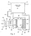
- a cooling system 60 includes a housing 62 with a first cylindrical portion 64 enclosing a blower fan 66, a second cylindrical portion 68 including a water injection unit or injector ring 70, and a third rectangular portion 72 enclosing an evaporator cooling element 74 and a heat exchange unit 76.
- First housing portion 64 may be substantially cylindrical with a uniform diameter.
- Fan 66 blows air from the atmosphere into the second housing portion 68.
- Second housing portion 68 has a larger diameter first end 78, a smaller diameter central portion 80 and a larger diameter second end 82 which is preferably larger than the diameter of the first end 78.
- the smaller diameter portion increases the speed of air movement past the injector ring 70.
- the evaporator cooling element 74 is porous, is mounted in plenum formed by a first end 84 of third housing portion 72, and is preferably removable therefrom. Element 74 assists in the evaporation of exhaust water and removes material from the air stream which would otherwise be deposited on the surfaces of the heat exchange unit 76.
- a line 75 communicates exhaust water from fuel cell stack water outlet 20 to the injector ring 70.
- the heat exchange unit or radiator 76 is mounted in the second end 86 of third housing portion 72. Radiator 76 includes hot coolant inlet 90 communicated via line 92 with coolant outlet 18 of fuel cell stack 10, and a coolant outlet 94 communicated via pump 96 and line 98 to coolant inlet 16 of fuel cell stack 10.
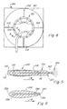
- the injector ring 70 includes an annular housing or web 100 centrally mounted in housing portion 80 by a plurality of radially extending support members 102.
- Injector ring 70 includes a plurality of injectors 104 which receive water from fuel cell stack water outlet 20. Each injector 104 produces a spray of exhaust water into the air flowing through the cooling unit 60.
- the injector ring annular housing 100 has an aerodynamic cross-sectional shape which tapers from a larger upstream end 110 to a thin smaller edge at its downstream end 112.
- An annular water supply tube 114 is enclosed in the larger end 110.
- Supply tube 114 receives stack exhaust water via line 75.
- Each injector 104 includes a generally cylindrical hollow body 116 with an upstream end 118 which receives water from the supply tube 114.
- the downstream end 120 of the body 116 forms an orifice or nozzle 122 which discharges a water spray 124 therefrom.
- Arrow A indicates the direction of airflow past the housing 100.
- the injector ring includes a one-piece annular housing 130 which has an aerodynamic cross-sectional shape which tapers from a larger upstream end 132 to a thin smaller edge at its downstream end 134.
- An annular water supply bore 136 is enclosed in the larger end 132.
- Supply bore 136 receives stack exhaust water via line 75.
- a plurality of injector bores 138 extend generally axially from supply bore 136 to corresponding nozzles 140 at the downstream end 134 of housing 130.
- Arrow B indicates the direction of airflow past the housing 130.
Landscapes
- Engineering & Computer Science (AREA)
- Chemical Kinetics & Catalysis (AREA)
- Manufacturing & Machinery (AREA)
- Sustainable Development (AREA)
- Sustainable Energy (AREA)
- Chemical & Material Sciences (AREA)
- Life Sciences & Earth Sciences (AREA)
- Electrochemistry (AREA)
- General Chemical & Material Sciences (AREA)
- Mechanical Engineering (AREA)
- General Engineering & Computer Science (AREA)
- Physics & Mathematics (AREA)
- Thermal Sciences (AREA)
- Fuel Cell (AREA)
Abstract
Description
- Fig. 1
- is a simplified schematic diagram of a fuel cell cooling system according to the present invention;
- Fig. 2
- is a detailed partial sectional perspective view of a portion of Fig. 1;
- Fig. 3
- is a simplified schematic diagram of an alternate embodiment of a fuel cell cooling system according to the present invention;
- Fig. 4
- is a view taken along lines 4-4 of Fig. 3;
- Fig. 5
- is a detailed perspective view of a portion of the injector ring in the direction of arrows 5-5 of Fig. 4;
- Fig. 6
- is a view similar to Fig. 5, but of an alternate embodiment.
Claims (14)
- A cooling system for a fuel cell stack (10) having a coolant inlet(16), a coolant outlet (18) and an exhaust water outlet (20), the cooling system comprising: a heat exchange unit (22, 76) coupled to the coolant inlet (16) and the coolant outlet (18); a blower (37, 66) for blowing air through the heat exchange unit (22, 76); an evaporator unit (54, 74) exposed to the blown air; and a conduit (40, 44, 75) communicating exhaust water from the exhaust water outlet (20) to the evaporator unit (54, 74), said exhaust water evaporating in the blown air and thereby cooling said air.
- Cooling system according to claim 1, wherein: the evaporator unit (54, 74) is mounted on the heat exchange unit (22, 76).
- Cooling system according to claim 1 or 2, wherein: the heat exchange unit (22) comprises a first or upper tank (24) communicated with the coolant outlet (18) and a second or lower tank (30) communicated with the coolant inlet (16); and the evaporator unit (54) is mounted on the first tank (24).
- Cooling system according to one or several of the previous claims, further comprising: a water storage tank (42) between the exhaust water outlet (20) and the evaporator unit (54).
- Cooling system according to one or several of the previous claims, wherein: a water distribution member (50) is attached to a side of the upper coolant tank (24), the water distribution member (50) having a plurality of weep holes (52) formed therein, the conduit (40, 44) communicating exhaust water to the water distribution member (50), the evaporator member (54) being mounted below the water distribution member (50) so that exhaust water flows through the weep holes (52) and into the preferably porous evaporation member (54).
- Cooling system according to claim 1, wherein the evaporator unit (74) comprises: a housing (62) having a first housing portion (64), a second housing portion (68) and a third housing portion (72); a blower (66) mounted in the first housing portion (64) for blowing air through the housing (62); the heat exchange unit (74) being mounted in the third housing portion (72); a water spraying unit (70) mounted in the second housing portion (68) between the first housing portion (64) and the third housing portion (72); and a water supply line (75) for communicating exhaust water from the fuel cell stack (10) to the water spraying unit (70), the water spraying unit (70) spraying said exhaust water into air blown through the housing (62), said exhaust water evaporating and cooling said air.
- Cooling system according to claim 6, wherein the water spraying unit (70) comprises: a plurality of water injectors (104) spaced apart from each other and/or arranged in an annular array.
- Cooling system according to claim 6 or 7, further comprising: a porous evaporator member (74) mounted in the housing (62) between the water spraying unit (70) and the heat exchange unit (76).
- Cooling system according to one or several of the previous claims, wherein in the water spraying unit (70) is mounted to be exposed to the blown air and comprising a plurality of water spray nozzles (122) spaced apart, the nozzles receiving exhaust water via the conduit (75) and spraying exhaust water into the blown air.
- Cooling system according to one or several of the claims, wherein the water spraying unit (70) comprises: an annular member (100, 130) mounted preferably in the housing (62) so as to be exposed to the blown air, the annular member (100, 130) having a larger upstream end (110, 132) and a smaller downstream end (112, 134) with respect to a direction of blown air; an annular water supply tube (114) receiving exhaust water via the conduit (75); and a plurality of water spray nozzles (122, 140) spaced apart and mounted on the annular member (100, 130), the nozzles (122, 140) receiving exhaust water from the supply tube (114) and spraying exhaust water into the blown air.
- Cooling system according to claim 10, wherein: the annular member (100, 130) is hollow and the water supply tube (114) is separate from and enclosed by the hollow annular member (100, 130) and/or the water supply tube (114) comprises an annular bore formed in the annular member (100, 130), whereby preferably each nozzle (122, 140) comprises an orifice in the annular member (100; 130), each orifice being communicated with the annular bore by a supply passage formed in the annular member (100, 130).
- Cooling system according to claim 10 to 11, wherein: the annular member (100, 130) has an aerodynamic shape.
- Cooling system according to one or several of the claims 10 to 12, further comprising: a plurality of radially extending support members (102) which support the annular member (100, 130) within and spaced apart from the housing (62).
- Cooling system according to one or several of the previous claims, further comprising: a coolant pump (96) for circulating coolant therethrough.
Applications Claiming Priority (2)
| Application Number | Priority Date | Filing Date | Title |
|---|---|---|---|
| US10/201,004 US6852435B2 (en) | 2002-07-23 | 2002-07-23 | Fuel cell cooling system |
| US201004 | 2002-07-23 |
Publications (2)
| Publication Number | Publication Date |
|---|---|
| EP1384967A2 true EP1384967A2 (en) | 2004-01-28 |
| EP1384967A3 EP1384967A3 (en) | 2006-09-13 |
Family
ID=30000078
Family Applications (1)
| Application Number | Title | Priority Date | Filing Date |
|---|---|---|---|
| EP03015150A Withdrawn EP1384967A3 (en) | 2002-07-23 | 2003-07-04 | Fuel cell cooling system |
Country Status (6)
| Country | Link |
|---|---|
| US (1) | US6852435B2 (en) |
| EP (1) | EP1384967A3 (en) |
| JP (2) | JP4669208B2 (en) |
| BR (1) | BR0301956B1 (en) |
| CA (1) | CA2424172A1 (en) |
| MX (1) | MXPA03006226A (en) |
Cited By (9)
| Publication number | Priority date | Publication date | Assignee | Title |
|---|---|---|---|---|
| KR100778204B1 (en) | 2006-10-24 | 2007-11-29 | 주식회사 효성 | Stack Cooling System for Air-Cooled Fuel Cells |
| EP2691304A4 (en) * | 2011-03-28 | 2014-12-24 | Rolls Royce Nam Tech Inc | AIRBORNE COOLING SYSTEM |
| US9534537B2 (en) | 2011-03-29 | 2017-01-03 | Rolls-Royce North American Technologies Inc. | Phase change material cooling system for a vehicle |
| US9771157B2 (en) | 2011-03-28 | 2017-09-26 | Rolls-Royce Corporation | Aircraft and airborne electrical power and thermal management system |
| WO2022148526A1 (en) * | 2021-01-05 | 2022-07-14 | Volvo Truck Corporation | Cooling system for a fuel cell system |
| DE102021103449A1 (en) | 2021-02-15 | 2022-08-18 | Man Truck & Bus Se | Evaporative cooling for a motor vehicle with a fuel cell drive |
| WO2022207311A1 (en) * | 2021-03-31 | 2022-10-06 | Mahle International Gmbh | Cooling arrangement for a fuel cell system |
| DE102023204915B3 (en) | 2023-05-25 | 2024-06-27 | GLOBE Fuel Cell Systems GmbH | Fuel cell system and electric vehicle |
| EP4414194A1 (en) * | 2023-02-07 | 2024-08-14 | Volvo Truck Corporation | Compressed air driven evaporative cooling system |
Families Citing this family (15)
| Publication number | Priority date | Publication date | Assignee | Title |
|---|---|---|---|---|
| KR100536218B1 (en) | 2004-01-28 | 2005-12-12 | 삼성에스디아이 주식회사 | Fuel cell system |
| US20070141420A1 (en) * | 2005-12-19 | 2007-06-21 | Voss Mark G | Fuel cell thermal management system and method |
| US9711808B2 (en) * | 2008-03-24 | 2017-07-18 | GM Global Technology Operations LLC | Method for optimized execution of heating tasks in fuel cell vehicles |
| AT507763B1 (en) * | 2008-12-30 | 2010-12-15 | Fronius Int Gmbh | METHOD AND DEVICE FOR TRANSFERRING CONSUMPTION AND PARTICULARLY EXPLOSIVE OPERATING MEDIA OF A FUEL CELL |
| US20150221964A1 (en) | 2014-02-01 | 2015-08-06 | Daimler Ag | Freeze start-up method for fuel cell system |
| JP2019121578A (en) * | 2018-01-11 | 2019-07-22 | トヨタ自動車株式会社 | Fuel cell system |
| JP7135512B2 (en) * | 2018-07-04 | 2022-09-13 | トヨタ自動車株式会社 | fuel cell system |
| DE102018120353A1 (en) * | 2018-08-21 | 2020-02-27 | Linde Material Handling Gmbh | Method for operating a fuel cell system of an industrial truck and corresponding fuel cell system |
| CN114623499B (en) * | 2020-12-11 | 2023-07-21 | 广东美的白色家电技术创新中心有限公司 | Air conditioner indoor unit and air conditioner |
| US11909078B2 (en) | 2021-03-15 | 2024-02-20 | Cummins Inc. | Systems and methods to utilize water output of fuel cell systems for evaporative cooling of radiators |
| DE102021206015A1 (en) * | 2021-06-14 | 2022-12-15 | Mahle International Gmbh | Method for operating a fuel cell system |
| DE102021206021A1 (en) * | 2021-06-14 | 2022-12-15 | Mahle International Gmbh | heat exchanger |
| DE102021206016A1 (en) | 2021-06-14 | 2022-12-15 | Mahle International Gmbh | Method for operating a fuel cell system |
| CN113471478B (en) * | 2021-07-16 | 2023-07-04 | 全球能源互联网研究院有限公司 | Cooling device and fuel cell system with same |
| WO2023209315A1 (en) * | 2022-04-29 | 2023-11-02 | Zeroavia Ltd | Cooling system for fuel cell onboard a vehicle including auxiliary evaporative cooling |
Family Cites Families (44)
| Publication number | Priority date | Publication date | Assignee | Title |
|---|---|---|---|---|
| DE1083838B (en) * | 1954-08-07 | 1960-06-23 | Gea Luftkuehler Ges M B H | Evaporative coolers, especially coolers for liquids |
| US3349839A (en) * | 1965-04-23 | 1967-10-31 | Priestley Ronald | Heat exchange apparatus |
| US3507702A (en) * | 1967-02-15 | 1970-04-21 | United Aircraft Corp | Fuel cell system including cooling and humidifying means |
| US3498844A (en) * | 1967-08-21 | 1970-03-03 | United Aircraft Corp | Fuel cell waste heat and water removal system |
| JPS4626904Y1 (en) * | 1968-03-29 | 1971-09-16 | ||
| US3761316A (en) * | 1971-03-29 | 1973-09-25 | United Aircraft Corp | Fuel cell with evaporative cooling |
| US3704172A (en) * | 1971-03-29 | 1972-11-28 | United Aircraft Corp | Dual mode fuel cell system |
| JPS4959137U (en) * | 1972-08-30 | 1974-05-24 | ||
| JPS5131950A (en) * | 1974-09-13 | 1976-03-18 | Shinwa Sangyo Kk | MITSUPEIGATAREIKYAKUTO |
| US3905884A (en) * | 1974-11-20 | 1975-09-16 | United Technologies Corp | Electrolysis cell system including recirculating product gas stream for cooling the cell |
| US4067205A (en) * | 1976-07-08 | 1978-01-10 | Jack Mayhue | Super cooler for an air conditioning system |
| US4107942A (en) * | 1977-03-31 | 1978-08-22 | Fairman Stanley W | Cooling system |
| JPS5937572Y2 (en) * | 1978-06-12 | 1984-10-18 | 三菱電機株式会社 | heat exchange equipment |
| JPS56110883A (en) * | 1980-02-06 | 1981-09-02 | Kawamoto Kogyo Kk | Cooling method |
| US4361525A (en) * | 1980-11-18 | 1982-11-30 | Leyland Billy M | Air cooling apparatus |
| JPS5894856U (en) * | 1981-12-22 | 1983-06-27 | アイシン精機株式会社 | Stirling engine for air conditioning system |
| JPS602145U (en) * | 1983-06-17 | 1985-01-09 | 株式会社荏原製作所 | Exhaust heat recovery heat exchanger |
| JPS6130968U (en) * | 1984-07-28 | 1986-02-25 | 株式会社 富士電機総合研究所 | fuel cell stack |
| JPS6163564U (en) * | 1984-09-28 | 1986-04-30 | ||
| JPH0653204B2 (en) * | 1985-09-21 | 1994-07-20 | 株式会社泉研究所 | Ultra-fine water droplet manufacturing equipment |
| JPS62123287A (en) * | 1985-11-25 | 1987-06-04 | Koken:Kk | Cooling processing device for heated fluid |
| US4706737A (en) * | 1986-11-20 | 1987-11-17 | International Fuel Cells Corporation | Fuel cell coolant inlet manifold and system |
| US4824740A (en) * | 1987-06-15 | 1989-04-25 | International Fuel Cell Corporation | Fuel cell stack cooling system |
| US4994331A (en) * | 1989-08-28 | 1991-02-19 | International Fuel Cells Corporation | Fuel cell evaporative cooling using fuel as a carrier gas |
| JPH0758129B2 (en) * | 1989-09-01 | 1995-06-21 | 三機工業株式会社 | Radiant heat radiator device |
| US5003789A (en) * | 1990-03-01 | 1991-04-02 | Manuel Gaona | Mist air conditioner for evaporative cooler |
| JPH0433861U (en) * | 1990-07-04 | 1992-03-19 | ||
| JPH04136695A (en) * | 1990-09-28 | 1992-05-11 | Toshiba Corp | Enclosed cooling tower |
| US5206094A (en) * | 1990-11-30 | 1993-04-27 | The United States Of America As Represented By The Secretary Of The Air Force | Fuel cell evaporative cooler |
| US5200278A (en) * | 1991-03-15 | 1993-04-06 | Ballard Power Systems, Inc. | Integrated fuel cell power generation system |
| JPH1054537A (en) * | 1996-08-12 | 1998-02-24 | Mitsui Eng & Shipbuild Co Ltd | Slag property adjusting method and slag generation device |
| US6066408A (en) * | 1997-08-07 | 2000-05-23 | Plug Power Inc. | Fuel cell cooler-humidifier plate |
| US5946932A (en) * | 1998-06-03 | 1999-09-07 | Wang; Huai-Wei | Multistage condensing structure |
| US6171718B1 (en) * | 1998-12-28 | 2001-01-09 | International Fuel Cells, Llc | Pressurized water recovery system for a fuel cell power plant |
| US6350535B1 (en) * | 1999-08-27 | 2002-02-26 | Plug Power Inc. | Mist evaporation system for fuel cell hydration |
| US6195999B1 (en) * | 2000-01-06 | 2001-03-06 | General Motors Corporation | Electrochemical engine |
| JP4839514B2 (en) * | 2000-02-21 | 2011-12-21 | 株式会社デンソー | Fuel cell system |
| JP2001351658A (en) * | 2000-06-05 | 2001-12-21 | Fuji Electric Co Ltd | Cooling equipment for fuel cell power generators |
| JP2001357864A (en) * | 2000-06-12 | 2001-12-26 | Toyo Radiator Co Ltd | Radiator in fuel cell system |
| JP2002184419A (en) * | 2000-12-14 | 2002-06-28 | Nissan Motor Co Ltd | Vehicle cooling system with fuel cell |
| US20020078704A1 (en) * | 2000-12-26 | 2002-06-27 | Stich John L. | Two stage evaporative cooling apparatus |
| JP2002313383A (en) * | 2001-04-11 | 2002-10-25 | Denso Corp | Fuel cell system |
| JP2002372385A (en) * | 2001-04-11 | 2002-12-26 | Denso Corp | Heat exchange equipment |
| JP3438725B2 (en) * | 2001-06-08 | 2003-08-18 | 日産自動車株式会社 | Vehicle cooling system |
-
2002
- 2002-07-23 US US10/201,004 patent/US6852435B2/en not_active Expired - Lifetime
-
2003
- 2003-04-01 CA CA002424172A patent/CA2424172A1/en not_active Abandoned
- 2003-05-26 JP JP2003147719A patent/JP4669208B2/en not_active Expired - Fee Related
- 2003-06-24 BR BRPI0301956-0A patent/BR0301956B1/en not_active IP Right Cessation
- 2003-07-04 EP EP03015150A patent/EP1384967A3/en not_active Withdrawn
- 2003-07-11 MX MXPA03006226A patent/MXPA03006226A/en active IP Right Grant
-
2010
- 2010-09-24 JP JP2010213713A patent/JP5307782B2/en not_active Expired - Fee Related
Cited By (12)
| Publication number | Priority date | Publication date | Assignee | Title |
|---|---|---|---|---|
| KR100778204B1 (en) | 2006-10-24 | 2007-11-29 | 주식회사 효성 | Stack Cooling System for Air-Cooled Fuel Cells |
| EP2691304A4 (en) * | 2011-03-28 | 2014-12-24 | Rolls Royce Nam Tech Inc | AIRBORNE COOLING SYSTEM |
| US8973868B2 (en) | 2011-03-28 | 2015-03-10 | Rolls Royce North American Technologies, Inc. | Airborne cooling system |
| US9771157B2 (en) | 2011-03-28 | 2017-09-26 | Rolls-Royce Corporation | Aircraft and airborne electrical power and thermal management system |
| US9534537B2 (en) | 2011-03-29 | 2017-01-03 | Rolls-Royce North American Technologies Inc. | Phase change material cooling system for a vehicle |
| US10358977B2 (en) | 2011-03-29 | 2019-07-23 | Rolls-Royce North American Technologies Inc. | Phase change material cooling system for a vehicle |
| WO2022148526A1 (en) * | 2021-01-05 | 2022-07-14 | Volvo Truck Corporation | Cooling system for a fuel cell system |
| DE102021103449A1 (en) | 2021-02-15 | 2022-08-18 | Man Truck & Bus Se | Evaporative cooling for a motor vehicle with a fuel cell drive |
| WO2022171402A1 (en) | 2021-02-15 | 2022-08-18 | Man Truck & Bus Se | Evaporative cooling for a motor vehicle with fuel-cell drive |
| WO2022207311A1 (en) * | 2021-03-31 | 2022-10-06 | Mahle International Gmbh | Cooling arrangement for a fuel cell system |
| EP4414194A1 (en) * | 2023-02-07 | 2024-08-14 | Volvo Truck Corporation | Compressed air driven evaporative cooling system |
| DE102023204915B3 (en) | 2023-05-25 | 2024-06-27 | GLOBE Fuel Cell Systems GmbH | Fuel cell system and electric vehicle |
Also Published As
| Publication number | Publication date |
|---|---|
| JP4669208B2 (en) | 2011-04-13 |
| BR0301956B1 (en) | 2012-02-07 |
| MXPA03006226A (en) | 2004-02-04 |
| EP1384967A3 (en) | 2006-09-13 |
| US6852435B2 (en) | 2005-02-08 |
| CA2424172A1 (en) | 2004-01-23 |
| BR0301956A (en) | 2004-08-24 |
| JP5307782B2 (en) | 2013-10-02 |
| JP2004055532A (en) | 2004-02-19 |
| JP2011040401A (en) | 2011-02-24 |
| US20040018405A1 (en) | 2004-01-29 |
Similar Documents
| Publication | Publication Date | Title |
|---|---|---|
| US6852435B2 (en) | Fuel cell cooling system | |
| US6250064B1 (en) | Gas turbine inlet air integrated water saturation and supersaturation system and related process | |
| US8216728B2 (en) | Device for treating reaction gases in fuel cells | |
| US6924051B2 (en) | Contact heater/humidifier for fuel cell systems | |
| US6699608B2 (en) | Method and apparatus for humidifying a gas flow and to a method for using such a device | |
| KR20180067255A (en) | Fuel cell system | |
| US8365530B2 (en) | System for conditioning the airflow entering a turbomachine | |
| KR102609395B1 (en) | Humidification and cooling device for fuel cell | |
| US20100086818A1 (en) | Recooling and humidification device for use in fuel cells | |
| CN218632129U (en) | Humidification system of fuel cell and fuel cell system | |
| US20060134482A1 (en) | Air humidification for fuel cell applications | |
| KR20050115288A (en) | Cathode inlet gas humidification system and method for a fuel cell system | |
| JP2020056564A (en) | Water spray cooling device | |
| KR20090088463A (en) | Humidifier for fuel cell stack using injector | |
| KR102595244B1 (en) | Humidification and cooling device for fuel cell | |
| JP2019044999A (en) | Water spray cooler | |
| CN102763257B (en) | There is the fuel cell system of at least one fuel cell | |
| JP4254508B2 (en) | Gas turbine system | |
| US20040076869A1 (en) | Fuel cell | |
| JP2007087761A (en) | In-vehicle fuel cell system | |
| JP2019045000A (en) | Water spray cooler | |
| KR20250163341A (en) | fuel cell system | |
| WO2022004157A1 (en) | Water spray cooling device | |
| CN222015451U (en) | Fuel cell stack humidification system and vehicle | |
| KR100819969B1 (en) | Humidification System of Fuel Cell Vehicle |
Legal Events
| Date | Code | Title | Description |
|---|---|---|---|
| PUAI | Public reference made under article 153(3) epc to a published international application that has entered the european phase |
Free format text: ORIGINAL CODE: 0009012 |
|
| AK | Designated contracting states |
Kind code of ref document: A2 Designated state(s): AT BE BG CH CY CZ DE DK EE ES FI FR GB GR HU IE IT LI LU MC NL PT RO SE SI SK TR |
|
| AX | Request for extension of the european patent |
Extension state: AL LT LV MK |
|
| PUAL | Search report despatched |
Free format text: ORIGINAL CODE: 0009013 |
|
| AK | Designated contracting states |
Kind code of ref document: A3 Designated state(s): AT BE BG CH CY CZ DE DK EE ES FI FR GB GR HU IE IT LI LU MC NL PT RO SE SI SK TR |
|
| AX | Request for extension of the european patent |
Extension state: AL LT LV MK |
|
| 17P | Request for examination filed |
Effective date: 20070313 |
|
| AKX | Designation fees paid |
Designated state(s): AT BE BG CH CY CZ DE DK EE ES FI FR GB GR HU IE IT LI LU MC NL PT RO SE SI SK TR |
|
| 17Q | First examination report despatched |
Effective date: 20080415 |
|
| STAA | Information on the status of an ep patent application or granted ep patent |
Free format text: STATUS: THE APPLICATION IS DEEMED TO BE WITHDRAWN |
|
| 18D | Application deemed to be withdrawn |
Effective date: 20081028 |