EP1384534B1 - Vorrichtung zur abschnittsweisen Autofrettage von Rohren - Google Patents
Vorrichtung zur abschnittsweisen Autofrettage von Rohren Download PDFInfo
- Publication number
- EP1384534B1 EP1384534B1 EP03009581A EP03009581A EP1384534B1 EP 1384534 B1 EP1384534 B1 EP 1384534B1 EP 03009581 A EP03009581 A EP 03009581A EP 03009581 A EP03009581 A EP 03009581A EP 1384534 B1 EP1384534 B1 EP 1384534B1
- Authority
- EP
- European Patent Office
- Prior art keywords
- ring
- insert
- sealing
- threaded sleeve
- tube
- Prior art date
- Legal status (The legal status is an assumption and is not a legal conclusion. Google has not performed a legal analysis and makes no representation as to the accuracy of the status listed.)
- Expired - Lifetime
Links
Images

Classifications
-
- B—PERFORMING OPERATIONS; TRANSPORTING
- B21—MECHANICAL METAL-WORKING WITHOUT ESSENTIALLY REMOVING MATERIAL; PUNCHING METAL
- B21C—MANUFACTURE OF METAL SHEETS, WIRE, RODS, TUBES, PROFILES OR LIKE SEMI-MANUFACTURED PRODUCTS OTHERWISE THAN BY ROLLING; AUXILIARY OPERATIONS USED IN CONNECTION WITH METAL-WORKING WITHOUT ESSENTIALLY REMOVING MATERIAL
- B21C37/00—Manufacture of metal sheets, rods, wire, tubes, profiles or like semi-manufactured products, not otherwise provided for; Manufacture of tubes of special shape
- B21C37/06—Manufacture of metal sheets, rods, wire, tubes, profiles or like semi-manufactured products, not otherwise provided for; Manufacture of tubes of special shape of tubes or metal hoses; Combined procedures for making tubes, e.g. for making multi-wall tubes
- B21C37/15—Making tubes of special shape; Making tube fittings
- B21C37/16—Making tubes with varying diameter in longitudinal direction
-
- B—PERFORMING OPERATIONS; TRANSPORTING
- B21—MECHANICAL METAL-WORKING WITHOUT ESSENTIALLY REMOVING MATERIAL; PUNCHING METAL
- B21C—MANUFACTURE OF METAL SHEETS, WIRE, RODS, TUBES, PROFILES OR LIKE SEMI-MANUFACTURED PRODUCTS OTHERWISE THAN BY ROLLING; AUXILIARY OPERATIONS USED IN CONNECTION WITH METAL-WORKING WITHOUT ESSENTIALLY REMOVING MATERIAL
- B21C1/00—Manufacture of metal sheets, wire, rods, tubes or like semi-manufactured products by drawing
- B21C1/16—Metal drawing by machines or apparatus in which the drawing action is effected by means other than drums, e.g. by a longitudinally-moved carriage pulling or pushing the work or stock for making metal sheets, rods or tubes
- B21C1/22—Metal drawing by machines or apparatus in which the drawing action is effected by means other than drums, e.g. by a longitudinally-moved carriage pulling or pushing the work or stock for making metal sheets, rods or tubes specially adapted for making tubular articles
- B21C1/24—Metal drawing by machines or apparatus in which the drawing action is effected by means other than drums, e.g. by a longitudinally-moved carriage pulling or pushing the work or stock for making metal sheets, rods or tubes specially adapted for making tubular articles by means of mandrels
-
- B—PERFORMING OPERATIONS; TRANSPORTING
- B21—MECHANICAL METAL-WORKING WITHOUT ESSENTIALLY REMOVING MATERIAL; PUNCHING METAL
- B21C—MANUFACTURE OF METAL SHEETS, WIRE, RODS, TUBES, PROFILES OR LIKE SEMI-MANUFACTURED PRODUCTS OTHERWISE THAN BY ROLLING; AUXILIARY OPERATIONS USED IN CONNECTION WITH METAL-WORKING WITHOUT ESSENTIALLY REMOVING MATERIAL
- B21C1/00—Manufacture of metal sheets, wire, rods, tubes or like semi-manufactured products by drawing
- B21C1/16—Metal drawing by machines or apparatus in which the drawing action is effected by means other than drums, e.g. by a longitudinally-moved carriage pulling or pushing the work or stock for making metal sheets, rods or tubes
- B21C1/22—Metal drawing by machines or apparatus in which the drawing action is effected by means other than drums, e.g. by a longitudinally-moved carriage pulling or pushing the work or stock for making metal sheets, rods or tubes specially adapted for making tubular articles
- B21C1/24—Metal drawing by machines or apparatus in which the drawing action is effected by means other than drums, e.g. by a longitudinally-moved carriage pulling or pushing the work or stock for making metal sheets, rods or tubes specially adapted for making tubular articles by means of mandrels
- B21C1/26—Push-bench drawing
-
- B—PERFORMING OPERATIONS; TRANSPORTING
- B21—MECHANICAL METAL-WORKING WITHOUT ESSENTIALLY REMOVING MATERIAL; PUNCHING METAL
- B21C—MANUFACTURE OF METAL SHEETS, WIRE, RODS, TUBES, PROFILES OR LIKE SEMI-MANUFACTURED PRODUCTS OTHERWISE THAN BY ROLLING; AUXILIARY OPERATIONS USED IN CONNECTION WITH METAL-WORKING WITHOUT ESSENTIALLY REMOVING MATERIAL
- B21C37/00—Manufacture of metal sheets, rods, wire, tubes, profiles or like semi-manufactured products, not otherwise provided for; Manufacture of tubes of special shape
- B21C37/06—Manufacture of metal sheets, rods, wire, tubes, profiles or like semi-manufactured products, not otherwise provided for; Manufacture of tubes of special shape of tubes or metal hoses; Combined procedures for making tubes, e.g. for making multi-wall tubes
- B21C37/15—Making tubes of special shape; Making tube fittings
- B21C37/152—Making rifle or gun barrels
-
- B—PERFORMING OPERATIONS; TRANSPORTING
- B23—MACHINE TOOLS; METAL-WORKING NOT OTHERWISE PROVIDED FOR
- B23P—METAL-WORKING NOT OTHERWISE PROVIDED FOR; COMBINED OPERATIONS; UNIVERSAL MACHINE TOOLS
- B23P9/00—Treating or finishing surfaces mechanically, with or without calibrating, primarily to resist wear or impact, e.g. smoothing or roughening turbine blades or bearings; Features of such surfaces not otherwise provided for, their treatment being unspecified
-
- C—CHEMISTRY; METALLURGY
- C21—METALLURGY OF IRON
- C21D—MODIFYING THE PHYSICAL STRUCTURE OF FERROUS METALS; GENERAL DEVICES FOR HEAT TREATMENT OF FERROUS OR NON-FERROUS METALS OR ALLOYS; MAKING METAL MALLEABLE, e.g. BY DECARBURISATION OR TEMPERING
- C21D7/00—Modifying the physical properties of iron or steel by deformation
- C21D7/02—Modifying the physical properties of iron or steel by deformation by cold working
- C21D7/10—Modifying the physical properties of iron or steel by deformation by cold working of the whole cross-section, e.g. of concrete reinforcing bars
- C21D7/12—Modifying the physical properties of iron or steel by deformation by cold working of the whole cross-section, e.g. of concrete reinforcing bars by expanding tubular bodies
Definitions
- the invention relates to a device for the partial autofrettage of pipes, in particular weapon tubes, by means of a hydraulic internal pressure generated inside the tube, according to the preamble of claim 1 (see e.g. US-A-1 391 009).
- the invention is based on the object, a device of the type mentioned to indicate a partial autofrettage.
- the invention is based essentially on the thought, at the end of the dome-shaped Metal insert to arrange a first sealing device, the one on a sealing seat having the insert arranged sealing packet, wherein the sealing seat on the front side a holding device is limited, which can be screwed onto the insert threaded sleeve and a subsequent to the threaded sleeve eck bath subsequent annular intermediate part.
- the sealing package comprises at least one through a shoulder of the mandrel-shaped Metal insert held O-ring, a leather ring, a support ring and one of two Partial rings existing high-pressure seal, wherein the partial rings conical contact surfaces have, such that upon pressurization of the high pressure seal one of the two Partial rings on the conical contact surface outwards against the inner wall of the Pipe and one of the two partial rings on the conical contact surface inwards against the metal insert is pressed, causing a seal at extremely high pressures.
- the sealing package by the Shoulder of the insert held elastic O-ring and one attached to the O-ring and the support ring supporting, consisting of leather ring comprises.
- this case takes over preferably made of rubber O-ring sealing in the bottom Print area.
- the e.g. made of commercially available cowhide existing leather ring prevents however, extruding the O-ring at higher pressures into the gap of the following Support ring.
- the existing of the two partial rings high pressure seal takes over then essentially only the seal at high pressures.
- FIG. 1 denotes a device according to the invention, which is a mandrel-shaped one Metal insert 2 includes, which with a first sealing device 3 for the caliber area a gun barrel is connected.
- the first sealing device 3 has a arranged on a sealing seat 4 on the metal insert 2 Sealing package 5, wherein the sealing seat 4 on the front side by a holding device 6 is limited, which can be screwed onto the metal insert 2 threaded sleeve 7 and a includes the threaded sleeve 7 rear subsequent annular intermediate part 8.
- the sealing package 5 comprises a held by a shoulder 9 of the metal insert 2 O-ring 10 of rubber, an adjoining leather ring 11, a support ring 12 and a consisting of two partial rings 13, 14 high-pressure seal 15 with conical contact surfaces 16.
- the support ring 12 and the two partial rings 13, 14 made Stole.
- the O-ring 10 is applied and takes over the seal in the lower pressure range.
- the support ring 12 presses on the first Partial ring 13, the increase in pressure on the conical contact surface 16 on the second sub-ring 14 is pushed. This will cause a radial expansion and a Pressing this partial ring 13 against the pipe inner wall and a radial compression and a compression of the partial ring 14 against the metal insert 2 and thus a seal against extreme high pressures causes.
- holes 18 are provided through which a gag-like Pin (not shown) can be plugged, which then for setting the first sealing packet. 5 is manually rotated.
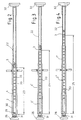
- FIGS. 2-4 22 designates a weapon barrel of a tank, which accordingly the gas pressure load at shot a gradually decreasing outer diameter along the gun barrel.
- the gun barrel 22 is hydraulically variable over a variable length autofrettiert, whereby here in the example in three differently to autofrettierende Pipe regions 23-25 is divided (Fig.2-4).
- the autofrettage pressures are p1, p2 and p3 for the individual pipe sections 23-25 according to the dimensions of the weapon barrel 22 so that p1> p2> p3.
- To perform the autofrettage is located the weapon barrel in a only schematically indicated pipe receiving device 32. A Subdivision into more or less Autofrettageabête is conceivable.
- the metal inserts 2, 2 'and 2 " an outer diameter which approximates the inner diameter of the gun barrel 22 comes.
- an additional filler piece 30 is used for this purpose in the cargo area area.
- the oil is supplied from the respective device 1, 1 'and 1 "receiving receiving device 26 ago via holes 31 in the metal insert 2, 2 'and 2 "
- the device 1 is first introduced into the weapon barrel 22, connected to the oil supply and then the gun barrel 22 in this tube area loaded with the pressure p1.
- the device 1 After completion of the autofrettage in the tube portion 23, the device 1 is the Weapon tube 22 removed and subsequently the device 1 'in the tube area 24th introduced ( Figure 3). Now, oil is introduced in this tube area, the gun barrel 22 loaded with a pressure p2 and the device 1 'the gun barrel 22 removed again.
- the autofrettage then takes place in the tube region 25 (FIG. 4) by introduction the device 1 "in the gun barrel 22 and appropriate pressurization the gun barrel 22 with an oil pressure p3.
- the thorn-shaped metal inserts 2, 2 'and 2 space annular, from the surface into the interior the metal inserts 2, 2 'and 2 "extending recesses 33 to the metal inserts 2, 2 ', 2 "easily introduced into the barrel 22 can.
Landscapes
- Engineering & Computer Science (AREA)
- Mechanical Engineering (AREA)
- Chemical & Material Sciences (AREA)
- Crystallography & Structural Chemistry (AREA)
- Materials Engineering (AREA)
- Metallurgy (AREA)
- Organic Chemistry (AREA)
- Shaping Metal By Deep-Drawing, Or The Like (AREA)
- Gasket Seals (AREA)
- Cleaning And De-Greasing Of Metallic Materials By Chemical Methods (AREA)
Description
- 1,1',1"
- Vorrichtung
- 2,2',2"
- Metalleinsatz, Einsatz
- 3
- erste Abdichteinrichtung
- 4
- Dichtsitz
- 5
- Dichtpaket
- 6
- Haltevorrichtung
- 7
- Gewindehülse
- 8
- Zwischenteil
- 9
- Schulter
- 10
- O-Ring
- 11
- Lederring
- 12
- Stützring
- 13
- erste Teilring
- 14
- zweite Teilring
- 15
- Hochdruckdichtung
- 16
- Berührungsfläche
- 17
- Gewinde
- 18
- Bohrung
- 19
- Schraubbolzen
- 20
- Gewinde
- 21
- Gewinde
- 22
- Rohr, Waffenrohr
- 23-25
- Rohrbereiche
- 26
- Aunahmeeinrichtung
- 27
- Kaliberbereich
- 28
- Ladungsraumbereich
- 29
- zweite Abdichteinrichtung
- 30
- Füllstück
- 31
- Bohrung
- 32
- Rohraufnahmeeinrichtung
- 33
- Vertiefungen
- 100
- Druckseite
Claims (8)
- Vorrichtung zur abschnittsweisen Autofrettage von Rohren (22), insbesondere Waffenrohren, mittels eines im Rohrinneren erzeugten hydraulischen Innendruckes, mit den Merkmalen:a) die Vorrichtung (1, 1', 1") umfaßt einen in das Rohr (22) vom Rohreingang aus einschiebbaren dornenförmigen Einsatz (2, 2', 2''), welcher mit einer ersten Abdichteinrichtung (3) verbunden ist;
gekennzeichnet durch die folgenden Merkmale:b) die erste Abdichteinrichtung (3) weist einen auf einem Dichtsitz (4) des Einsatzes (2, 2', 2") angeordnetes Dichtpaket (5) auf, wobei der Dichtsitz (4) vorderseitig durch eine Haltevorrichtung (6) begrenzt ist, die eine auf den Einsatz (2, 2', 2") aufschraubbare Gewindehülse (7) und ein sich an die Gewindehülse (7) heckseitig anschließendes ringförmiges Zwischenteil (8) umfaßt;c) das Dichtpaket (5) umfaßt mindestens einen durch eine Schulter (9) des Einsatzes (2, 2', 2") gehaltenen O-Ring (10), einen Lederring (11), einen Stützring (12) und einer aus zwei Teilringen (13, 14) bestehenden Hochdruckdichtung (15), wobei die Teilringe (13, 14) über eine konische Berührungsfläche (16) miteinander verbunden sind, derart, daß bei Druckbeaufschlagung der Hochdruckdichtung (15) einer der beiden Teilringe (13, 14) über die konische Berührungsfläche (16) nach außen gegen die Innenwand des Waffenrohres (22) und einer der beiden Teilringe (13, 14) über die konische Berührungsfläche (16) nach innen gegen den Metalleinsatz (2) gedrückt wird. - Vorrichtung nach Anspruch 1, dadurch gekennzeichnet, daß der O-Ring (10) des Dichtpaketes (5) elastisch ist und durch die Schulter (9) des Einsatzes (2, 2', 2") gehalten ist und der Lederring (11) sich an dem O-Ring (10) und dem Stützring (12) abstützt.
- Vorrichtung nach Anspruch 1 oder 2, dadurch gekennzeichnet, daß in die Gewindehülse (7) der Haltevorrichtung (6) auf der dem Dichtpaket (5) abgewandten Seite ein Schraubbolzen (19) eingesetzt ist, wobei das Gewinde (20) der Gewindehülse (7) in diesem Bereich entgegengesetzt gerichtet ist zu dem restlichen Gewinde (21), so daß durch Drehung des Schraubbolzens (19) die Gewindehülse (7) vom Dichtpaket (5) weg drehbar ist.
- Vorrichtung nach einem der Ansprüche 1 bis 3, dadurch gekennzeichnet, daß der O-Ring (10) aus Gummi besteht.
- Vorrichtung nach einem der Ansprüche 1 bis 4, dadurch gekennzeichnet, daß die beiden Teilringe (13, 14) der Hochdruckdichtung (15) aus Stahl bestehen.
- Vorrichtung nach einem der Ansprüche 1 bis 5, dadurch gekennzeichnet, daß der Lederring (11) aus Rindsleder besteht.
- Vorrichtung nach einem der Ansprüche 1 bis 6, dadurch gekennzeichnet, daß der dornenförmige Einsatz (2, 2', 2") auf seiner dem Rohreingang des Rohres (22) zugewandten Seite mit einer zweiten Abdichteinrichtung (29) verbunden ist, deren Aufbau der ersten Abdichteinrichtung (3) im wesentlichen entspricht.
- Vorrichtung nach einem der Ansprüche 1 bis 7, dadurch gekennzeichnet, daß der dornenförmige Einsatz (2, 2', 2") mit voneinander beabstandeten ringförmigen, sich von der Oberfläche in das Innere des Einsatzes (2, 2', 2") erstreckenden Vertiefungen (33) versehen ist.
Applications Claiming Priority (2)
| Application Number | Priority Date | Filing Date | Title |
|---|---|---|---|
| DE10234029A DE10234029A1 (de) | 2002-07-26 | 2002-07-26 | Vorrichtung zur abschnittsweisen Autofrettage von Rohren |
| DE10234029 | 2002-07-26 |
Publications (2)
| Publication Number | Publication Date |
|---|---|
| EP1384534A1 EP1384534A1 (de) | 2004-01-28 |
| EP1384534B1 true EP1384534B1 (de) | 2005-01-19 |
Family
ID=29796575
Family Applications (1)
| Application Number | Title | Priority Date | Filing Date |
|---|---|---|---|
| EP03009581A Expired - Lifetime EP1384534B1 (de) | 2002-07-26 | 2003-04-29 | Vorrichtung zur abschnittsweisen Autofrettage von Rohren |
Country Status (6)
| Country | Link |
|---|---|
| US (1) | US6931776B2 (de) |
| EP (1) | EP1384534B1 (de) |
| JP (1) | JP4718109B2 (de) |
| AT (1) | ATE287302T1 (de) |
| DE (2) | DE10234029A1 (de) |
| ES (1) | ES2233894T3 (de) |
Cited By (1)
| Publication number | Priority date | Publication date | Assignee | Title |
|---|---|---|---|---|
| WO2018134063A1 (de) | 2017-01-20 | 2018-07-26 | Uhde High Pressure Technologies Gmbh | Vorrichtung und verfahren zum autofrettieren eines werkstücks |
Families Citing this family (16)
| Publication number | Priority date | Publication date | Assignee | Title |
|---|---|---|---|---|
| US6810615B2 (en) * | 2003-02-05 | 2004-11-02 | United Defense, L.P. | Method for gun barrel manufacture using tailored autofrettage mandrels |
| US7922065B2 (en) | 2004-08-02 | 2011-04-12 | Ati Properties, Inc. | Corrosion resistant fluid conducting parts, methods of making corrosion resistant fluid conducting parts and equipment and parts replacement methods utilizing corrosion resistant fluid conducting parts |
| US8418392B2 (en) | 2007-08-13 | 2013-04-16 | The United States Of America As Represented By The Secretary Of The Army | Compressed elastomer process for autofrettage and lining tubes |
| US7818986B1 (en) * | 2007-05-23 | 2010-10-26 | The United States Of America As Represented By The Secretary Of The Army | Multiple autofrettage |
| US8579075B2 (en) | 2008-03-13 | 2013-11-12 | Advanced Armament Corp., Llc | Blackout silencer |
| US8474361B2 (en) * | 2008-05-05 | 2013-07-02 | Advanced Armament Corp., Llc | Process to produce a silencer tube with minimal wall thickness |
| US8424441B2 (en) | 2009-08-20 | 2013-04-23 | Advanced Armament Corp. | Firearm suppressor booster system |
| US8910409B1 (en) * | 2010-02-09 | 2014-12-16 | Ati Properties, Inc. | System and method of producing autofrettage in tubular components using a flowforming process |
| US8869443B2 (en) | 2011-03-02 | 2014-10-28 | Ati Properties, Inc. | Composite gun barrel with outer sleeve made from shape memory alloy to dampen firing vibrations |
| FI20125892A7 (fi) * | 2012-08-29 | 2014-03-01 | Carrel Innovations Oy | Menetelmä valmistaa aseen patruunapesää |
| US10118259B1 (en) | 2012-12-11 | 2018-11-06 | Ati Properties Llc | Corrosion resistant bimetallic tube manufactured by a two-step process |
| US9638357B1 (en) | 2015-06-24 | 2017-05-02 | Omax Corporation | Mechanical processing of high aspect ratio metallic tubing and related technology |
| DE102015212868A1 (de) * | 2015-07-09 | 2017-01-12 | Hirschvogel Umformtechnik Gmbh | Innendruckbelastetes Bauteil |
| US12403621B2 (en) | 2019-12-20 | 2025-09-02 | Hypertherm, Inc. | Motorized systems and associated methods for controlling an adjustable dump orifice on a liquid jet cutting system |
| EP4127527A1 (de) | 2020-03-24 | 2023-02-08 | Hypertherm, Inc. | Hochdruckdichtung für ein flüssigkeitsstrahlschneidsystem |
| KR20230005840A (ko) | 2020-03-30 | 2023-01-10 | 하이퍼썸, 인크. | 다기능 접속 종방향 단부들을 갖는 액체 제트 펌프를 위한 실린더 |
Family Cites Families (10)
| Publication number | Priority date | Publication date | Assignee | Title |
|---|---|---|---|---|
| US1495587A (en) * | 1919-01-10 | 1924-05-27 | Kas So Kitch E Mon E Too So Ne | Terminal for auto internal forging of tubes |
| US1391009A (en) * | 1919-03-31 | 1921-09-20 | Schneider & Cie | Process and apparatus for the manufacture of metal tubes by the selfhooping process |
| US1553824A (en) * | 1925-03-28 | 1925-09-15 | Tracy C Dickson | Method of and apparatus for making metallic articles |
| US1725836A (en) * | 1925-06-12 | 1929-08-27 | Frederick C Langenberg | Packing for high-pressure joints |
| GB805253A (en) * | 1955-11-25 | 1958-12-03 | Trist & Co Ltd Ronald | Improvements relating to packing rings |
| DE1124987B (de) * | 1956-04-27 | 1962-03-08 | James Francois Emile Basset | Verfahren und Vorrichtung zur Autofrettage von Rohren, insbesondere von Kanonenrohrrohlingen |
| US3767215A (en) * | 1972-09-01 | 1973-10-23 | Us Navy | Multi-ring hydraulic seal for irregular bore surfaces |
| JPS636271A (ja) * | 1986-06-25 | 1988-01-12 | Japan Steel Works Ltd:The | 高圧筒の加圧時の超高圧シ−リング装置 |
| US4848777A (en) * | 1987-09-18 | 1989-07-18 | Fmc Corporation | Pressure energized/pressure intensified casing seal |
| DE4115284A1 (de) * | 1991-05-10 | 1992-11-12 | Rheinmetall Gmbh | Autofrettagevorrichtung fuer rohre |
-
2002
- 2002-07-26 DE DE10234029A patent/DE10234029A1/de not_active Withdrawn
-
2003
- 2003-04-29 AT AT03009581T patent/ATE287302T1/de not_active IP Right Cessation
- 2003-04-29 EP EP03009581A patent/EP1384534B1/de not_active Expired - Lifetime
- 2003-04-29 DE DE50300263T patent/DE50300263D1/de not_active Expired - Lifetime
- 2003-04-29 ES ES03009581T patent/ES2233894T3/es not_active Expired - Lifetime
- 2003-07-16 JP JP2003197654A patent/JP4718109B2/ja not_active Expired - Lifetime
- 2003-07-21 US US10/622,485 patent/US6931776B2/en not_active Expired - Lifetime
Cited By (3)
| Publication number | Priority date | Publication date | Assignee | Title |
|---|---|---|---|---|
| WO2018134063A1 (de) | 2017-01-20 | 2018-07-26 | Uhde High Pressure Technologies Gmbh | Vorrichtung und verfahren zum autofrettieren eines werkstücks |
| DE102017200917A1 (de) | 2017-01-20 | 2018-07-26 | Thyssenkrupp Ag | Vorrichtung und Verfahren zum Autofrettieren eines Werkstücks |
| US11298737B2 (en) | 2017-01-20 | 2022-04-12 | Uhde High Pressure Technologies Gmbh | Device and method for the autofrettage of a workpiece |
Also Published As
| Publication number | Publication date |
|---|---|
| US20040103576A1 (en) | 2004-06-03 |
| JP2004058156A (ja) | 2004-02-26 |
| ES2233894T3 (es) | 2005-06-16 |
| JP4718109B2 (ja) | 2011-07-06 |
| DE10234029A1 (de) | 2004-02-05 |
| ATE287302T1 (de) | 2005-02-15 |
| EP1384534A1 (de) | 2004-01-28 |
| DE50300263D1 (de) | 2005-02-24 |
| US6931776B2 (en) | 2005-08-23 |
Similar Documents
| Publication | Publication Date | Title |
|---|---|---|
| EP1384534A1 (de) | Vorrichtung zur abschnittsweisen Autofrettage von Rohren | |
| CH686739A5 (de) | Verfahren zum Befestigen eines Schlauches an einem Nippel und eine Schlauchverbindung, hergestellt nach diesem Verfahren. | |
| DE102006054440B3 (de) | Autofrettageverfahren und Autofrettagevorrichtung | |
| DE2614830A1 (de) | Rohr-fitting | |
| DE2731242C2 (de) | Verbindungsanordnung für zwei Rohre mit Blockierung bei Zugbeanspruchung | |
| DD295899A5 (de) | Verfahren und vorrichtung zur auskleidung installierter rohrleitungen | |
| EP0512160B1 (de) | Autofrettagevorrichtung für Rohre | |
| DE2232679A1 (de) | Patronenlager fuer automatische waffen | |
| EP0824383B1 (de) | Presswerkzeug und verfahren zum verbinden von rohrförmigen elementen | |
| DE10000796A1 (de) | Verfahren und Vorrichtung zur Autofrettage von fertig gebogenen oder sonst umgeformten Rohleitungen | |
| DE19751413C2 (de) | Verfahren und Vorrichtung zur Verminderung der Wandreibung beim Innenhochdruck-Umformungsprozess | |
| EP2149024B1 (de) | Vorrichtung und verfahren zur befestigung einer mündungsbremse an einem waffenrohr | |
| EP0501363B1 (de) | Rohrverbindung | |
| DE4138174C2 (de) | Kolbenpumpe | |
| DE69212197T2 (de) | Zylinder-Kolben-Stelleinrichtung | |
| DE19855795B4 (de) | Schneidringverschraubung für Druckmittel-Rohrleitungen | |
| DE102009040822A1 (de) | Rohrverbinder zum dichten Verbinden an ein Rohrende eines Rohres aus nachgiebigem Werkstoff | |
| DE202017104354U1 (de) | Vorrichtung zur hydrodynamischen Beseitigung von Störstellen im Inneren von Rohrleitungen, insbesondere zur Sanierung und Reinigung von wasserführenden Rohrleitungen im häuslichen, kommunalen und industriellen Bereich | |
| DE3147396C2 (de) | Molch zum Auskleiden von Rohrleitungen | |
| DE102014215878A1 (de) | Spur- oder Lenkstange für ein Fahrzeug | |
| EP2158047A1 (de) | Mehrteilige walze | |
| DE4445057C2 (de) | Verschraubung für ein Innenwerkzeug einer Lochpresse | |
| DE2925579C2 (de) | Werkzeug zur Bearbeitung der Innenflächen von Werkstücken durch Verformung | |
| EP3378577B1 (de) | Hydraulische spannvorrichtung für die demontierbare, reibschlüssige verbindung zweier bauteile | |
| DE102016105194A1 (de) | Verfahren zur Herstellung einer Pressverbindung |
Legal Events
| Date | Code | Title | Description |
|---|---|---|---|
| PUAI | Public reference made under article 153(3) epc to a published international application that has entered the european phase |
Free format text: ORIGINAL CODE: 0009012 |
|
| 17P | Request for examination filed |
Effective date: 20031118 |
|
| AK | Designated contracting states |
Kind code of ref document: A1 Designated state(s): AT BE BG CH CY CZ DE DK EE ES FI FR GB GR HU IE IT LI LU MC NL PT RO SE SI SK TR |
|
| AX | Request for extension of the european patent |
Extension state: AL LT LV MK |
|
| GRAP | Despatch of communication of intention to grant a patent |
Free format text: ORIGINAL CODE: EPIDOSNIGR1 |
|
| GRAS | Grant fee paid |
Free format text: ORIGINAL CODE: EPIDOSNIGR3 |
|
| RAP1 | Party data changed (applicant data changed or rights of an application transferred) |
Owner name: RHEINMETALL WAFFE MUNITION GMBH |
|
| AKX | Designation fees paid |
Designated state(s): AT BE BG CH CY CZ DE DK EE ES FI FR GB GR HU IE IT LI LU MC NL PT RO SE SI SK TR |
|
| GRAA | (expected) grant |
Free format text: ORIGINAL CODE: 0009210 |
|
| AK | Designated contracting states |
Kind code of ref document: B1 Designated state(s): AT BE BG CH CY CZ DE DK EE ES FI FR GB GR HU IE IT LI LU MC NL PT RO SE SI SK TR |
|
| PG25 | Lapsed in a contracting state [announced via postgrant information from national office to epo] |
Ref country code: FI Free format text: LAPSE BECAUSE OF FAILURE TO SUBMIT A TRANSLATION OF THE DESCRIPTION OR TO PAY THE FEE WITHIN THE PRESCRIBED TIME-LIMIT Effective date: 20050119 Ref country code: NL Free format text: LAPSE BECAUSE OF FAILURE TO SUBMIT A TRANSLATION OF THE DESCRIPTION OR TO PAY THE FEE WITHIN THE PRESCRIBED TIME-LIMIT Effective date: 20050119 Ref country code: IE Free format text: LAPSE BECAUSE OF FAILURE TO SUBMIT A TRANSLATION OF THE DESCRIPTION OR TO PAY THE FEE WITHIN THE PRESCRIBED TIME-LIMIT Effective date: 20050119 Ref country code: BG Free format text: LAPSE BECAUSE OF FAILURE TO SUBMIT A TRANSLATION OF THE DESCRIPTION OR TO PAY THE FEE WITHIN THE PRESCRIBED TIME-LIMIT Effective date: 20050119 Ref country code: RO Free format text: LAPSE BECAUSE OF FAILURE TO SUBMIT A TRANSLATION OF THE DESCRIPTION OR TO PAY THE FEE WITHIN THE PRESCRIBED TIME-LIMIT Effective date: 20050119 Ref country code: EE Free format text: LAPSE BECAUSE OF FAILURE TO SUBMIT A TRANSLATION OF THE DESCRIPTION OR TO PAY THE FEE WITHIN THE PRESCRIBED TIME-LIMIT Effective date: 20050119 Ref country code: SK Free format text: LAPSE BECAUSE OF FAILURE TO SUBMIT A TRANSLATION OF THE DESCRIPTION OR TO PAY THE FEE WITHIN THE PRESCRIBED TIME-LIMIT Effective date: 20050119 Ref country code: SI Free format text: LAPSE BECAUSE OF FAILURE TO SUBMIT A TRANSLATION OF THE DESCRIPTION OR TO PAY THE FEE WITHIN THE PRESCRIBED TIME-LIMIT Effective date: 20050119 Ref country code: CZ Free format text: LAPSE BECAUSE OF FAILURE TO SUBMIT A TRANSLATION OF THE DESCRIPTION OR TO PAY THE FEE WITHIN THE PRESCRIBED TIME-LIMIT Effective date: 20050119 |
|
| REG | Reference to a national code |
Ref country code: GB Ref legal event code: FG4D Free format text: NOT ENGLISH |
|
| REG | Reference to a national code |
Ref country code: CH Ref legal event code: NV Representative=s name: E. BLUM & CO. PATENTANWAELTE Ref country code: CH Ref legal event code: EP |
|
| GBT | Gb: translation of ep patent filed (gb section 77(6)(a)/1977) |
Effective date: 20050119 |
|
| REG | Reference to a national code |
Ref country code: SE Ref legal event code: TRGR |
|
| REG | Reference to a national code |
Ref country code: IE Ref legal event code: FG4D Free format text: GERMAN |
|
| REF | Corresponds to: |
Ref document number: 50300263 Country of ref document: DE Date of ref document: 20050224 Kind code of ref document: P |
|
| PG25 | Lapsed in a contracting state [announced via postgrant information from national office to epo] |
Ref country code: DK Free format text: LAPSE BECAUSE OF FAILURE TO SUBMIT A TRANSLATION OF THE DESCRIPTION OR TO PAY THE FEE WITHIN THE PRESCRIBED TIME-LIMIT Effective date: 20050419 |
|
| PG25 | Lapsed in a contracting state [announced via postgrant information from national office to epo] |
Ref country code: HU Free format text: LAPSE BECAUSE OF FAILURE TO SUBMIT A TRANSLATION OF THE DESCRIPTION OR TO PAY THE FEE WITHIN THE PRESCRIBED TIME-LIMIT Effective date: 20050420 |
|
| REG | Reference to a national code |
Ref country code: GR Ref legal event code: EP Ref document number: 20050400978 Country of ref document: GR |
|
| PG25 | Lapsed in a contracting state [announced via postgrant information from national office to epo] |
Ref country code: CY Free format text: LAPSE BECAUSE OF FAILURE TO SUBMIT A TRANSLATION OF THE DESCRIPTION OR TO PAY THE FEE WITHIN THE PRESCRIBED TIME-LIMIT Effective date: 20050429 Ref country code: LU Free format text: LAPSE BECAUSE OF NON-PAYMENT OF DUE FEES Effective date: 20050429 Ref country code: AT Free format text: LAPSE BECAUSE OF NON-PAYMENT OF DUE FEES Effective date: 20050429 |
|
| PG25 | Lapsed in a contracting state [announced via postgrant information from national office to epo] |
Ref country code: MC Free format text: LAPSE BECAUSE OF NON-PAYMENT OF DUE FEES Effective date: 20050430 Ref country code: BE Free format text: LAPSE BECAUSE OF NON-PAYMENT OF DUE FEES Effective date: 20050430 |
|
| REG | Reference to a national code |
Ref country code: ES Ref legal event code: FG2A Ref document number: 2233894 Country of ref document: ES Kind code of ref document: T3 |
|
| NLV1 | Nl: lapsed or annulled due to failure to fulfill the requirements of art. 29p and 29m of the patents act | ||
| REG | Reference to a national code |
Ref country code: IE Ref legal event code: FD4D |
|
| BERE | Be: lapsed |
Owner name: RHEINMETALL WAFFE MUNITION G.M.B.H. Effective date: 20050430 |
|
| PLBE | No opposition filed within time limit |
Free format text: ORIGINAL CODE: 0009261 |
|
| STAA | Information on the status of an ep patent application or granted ep patent |
Free format text: STATUS: NO OPPOSITION FILED WITHIN TIME LIMIT |
|
| ET | Fr: translation filed | ||
| 26N | No opposition filed |
Effective date: 20051020 |
|
| PGFP | Annual fee paid to national office [announced via postgrant information from national office to epo] |
Ref country code: ES Payment date: 20070427 Year of fee payment: 5 |
|
| REG | Reference to a national code |
Ref country code: CH Ref legal event code: PFA Owner name: RHEINMETALL WAFFE MUNITION GMBH Free format text: RHEINMETALL WAFFE MUNITION GMBH#LIEBIGSTRASSE 17#84544 ASCHAU AM INN (DE) -TRANSFER TO- RHEINMETALL WAFFE MUNITION GMBH#LIEBIGSTRASSE 17#84544 ASCHAU AM INN (DE) |
|
| PGFP | Annual fee paid to national office [announced via postgrant information from national office to epo] |
Ref country code: GB Payment date: 20070426 Year of fee payment: 5 |
|
| BERE | Be: lapsed |
Owner name: RHEINMETALL WAFFE MUNITION G.M.B.H. Effective date: 20050430 |
|
| PG25 | Lapsed in a contracting state [announced via postgrant information from national office to epo] |
Ref country code: PT Free format text: LAPSE BECAUSE OF NON-PAYMENT OF DUE FEES Effective date: 20050619 |
|
| PGFP | Annual fee paid to national office [announced via postgrant information from national office to epo] |
Ref country code: FR Payment date: 20070416 Year of fee payment: 5 |
|
| PGFP | Annual fee paid to national office [announced via postgrant information from national office to epo] |
Ref country code: GR Payment date: 20070420 Year of fee payment: 5 |
|
| GBPC | Gb: european patent ceased through non-payment of renewal fee |
Effective date: 20080429 |
|
| REG | Reference to a national code |
Ref country code: FR Ref legal event code: ST Effective date: 20081231 |
|
| PG25 | Lapsed in a contracting state [announced via postgrant information from national office to epo] |
Ref country code: FR Free format text: LAPSE BECAUSE OF NON-PAYMENT OF DUE FEES Effective date: 20080430 |
|
| REG | Reference to a national code |
Ref country code: ES Ref legal event code: FD2A Effective date: 20080430 |
|
| PG25 | Lapsed in a contracting state [announced via postgrant information from national office to epo] |
Ref country code: GB Free format text: LAPSE BECAUSE OF NON-PAYMENT OF DUE FEES Effective date: 20080429 Ref country code: GR Free format text: LAPSE BECAUSE OF NON-PAYMENT OF DUE FEES Effective date: 20081104 |
|
| PG25 | Lapsed in a contracting state [announced via postgrant information from national office to epo] |
Ref country code: ES Free format text: LAPSE BECAUSE OF NON-PAYMENT OF DUE FEES Effective date: 20080430 |
|
| REG | Reference to a national code |
Ref country code: DE Ref legal event code: R084 Ref document number: 50300263 Country of ref document: DE |
|
| PGFP | Annual fee paid to national office [announced via postgrant information from national office to epo] |
Ref country code: SE Payment date: 20220421 Year of fee payment: 20 Ref country code: IT Payment date: 20220420 Year of fee payment: 20 Ref country code: DE Payment date: 20220420 Year of fee payment: 20 |
|
| PGFP | Annual fee paid to national office [announced via postgrant information from national office to epo] |
Ref country code: TR Payment date: 20220428 Year of fee payment: 20 Ref country code: CH Payment date: 20220421 Year of fee payment: 20 |
|
| REG | Reference to a national code |
Ref country code: DE Ref legal event code: R071 Ref document number: 50300263 Country of ref document: DE |
|
| REG | Reference to a national code |
Ref country code: CH Ref legal event code: PL |
|
| REG | Reference to a national code |
Ref country code: SE Ref legal event code: EUG |