EP1384456A2 - Vorrichtung zur Rekonstruktion der Hüftgelenkpfanne - Google Patents
Vorrichtung zur Rekonstruktion der Hüftgelenkpfanne Download PDFInfo
- Publication number
- EP1384456A2 EP1384456A2 EP03254588A EP03254588A EP1384456A2 EP 1384456 A2 EP1384456 A2 EP 1384456A2 EP 03254588 A EP03254588 A EP 03254588A EP 03254588 A EP03254588 A EP 03254588A EP 1384456 A2 EP1384456 A2 EP 1384456A2
- Authority
- EP
- European Patent Office
- Prior art keywords
- trial
- acetabular prosthesis
- shell
- acetabular
- orientation
- Prior art date
- Legal status (The legal status is an assumption and is not a legal conclusion. Google has not performed a legal analysis and makes no representation as to the accuracy of the status listed.)
- Granted
Links
Images


Classifications
-
- A—HUMAN NECESSITIES
- A61—MEDICAL OR VETERINARY SCIENCE; HYGIENE
- A61F—FILTERS IMPLANTABLE INTO BLOOD VESSELS; PROSTHESES; DEVICES PROVIDING PATENCY TO, OR PREVENTING COLLAPSING OF, TUBULAR STRUCTURES OF THE BODY, e.g. STENTS; ORTHOPAEDIC, NURSING OR CONTRACEPTIVE DEVICES; FOMENTATION; TREATMENT OR PROTECTION OF EYES OR EARS; BANDAGES, DRESSINGS OR ABSORBENT PADS; FIRST-AID KITS
- A61F2/00—Filters implantable into blood vessels; Prostheses, i.e. artificial substitutes or replacements for parts of the body; Appliances for connecting them with the body; Devices providing patency to, or preventing collapsing of, tubular structures of the body, e.g. stents
- A61F2/02—Prostheses implantable into the body
- A61F2/30—Joints
- A61F2/30721—Accessories
- A61F2/30724—Spacers for centering an implant in a bone cavity, e.g. in a cement-receiving cavity
-
- A—HUMAN NECESSITIES
- A61—MEDICAL OR VETERINARY SCIENCE; HYGIENE
- A61F—FILTERS IMPLANTABLE INTO BLOOD VESSELS; PROSTHESES; DEVICES PROVIDING PATENCY TO, OR PREVENTING COLLAPSING OF, TUBULAR STRUCTURES OF THE BODY, e.g. STENTS; ORTHOPAEDIC, NURSING OR CONTRACEPTIVE DEVICES; FOMENTATION; TREATMENT OR PROTECTION OF EYES OR EARS; BANDAGES, DRESSINGS OR ABSORBENT PADS; FIRST-AID KITS
- A61F2/00—Filters implantable into blood vessels; Prostheses, i.e. artificial substitutes or replacements for parts of the body; Appliances for connecting them with the body; Devices providing patency to, or preventing collapsing of, tubular structures of the body, e.g. stents
- A61F2/02—Prostheses implantable into the body
- A61F2/30—Joints
- A61F2/30721—Accessories
- A61F2/30734—Modular inserts, sleeves or augments, e.g. placed on proximal part of stem for fixation purposes or wedges for bridging a bone defect
-
- A—HUMAN NECESSITIES
- A61—MEDICAL OR VETERINARY SCIENCE; HYGIENE
- A61F—FILTERS IMPLANTABLE INTO BLOOD VESSELS; PROSTHESES; DEVICES PROVIDING PATENCY TO, OR PREVENTING COLLAPSING OF, TUBULAR STRUCTURES OF THE BODY, e.g. STENTS; ORTHOPAEDIC, NURSING OR CONTRACEPTIVE DEVICES; FOMENTATION; TREATMENT OR PROTECTION OF EYES OR EARS; BANDAGES, DRESSINGS OR ABSORBENT PADS; FIRST-AID KITS
- A61F2/00—Filters implantable into blood vessels; Prostheses, i.e. artificial substitutes or replacements for parts of the body; Appliances for connecting them with the body; Devices providing patency to, or preventing collapsing of, tubular structures of the body, e.g. stents
- A61F2/02—Prostheses implantable into the body
- A61F2/30—Joints
- A61F2/32—Joints for the hip
- A61F2/34—Acetabular cups
-
- A—HUMAN NECESSITIES
- A61—MEDICAL OR VETERINARY SCIENCE; HYGIENE
- A61F—FILTERS IMPLANTABLE INTO BLOOD VESSELS; PROSTHESES; DEVICES PROVIDING PATENCY TO, OR PREVENTING COLLAPSING OF, TUBULAR STRUCTURES OF THE BODY, e.g. STENTS; ORTHOPAEDIC, NURSING OR CONTRACEPTIVE DEVICES; FOMENTATION; TREATMENT OR PROTECTION OF EYES OR EARS; BANDAGES, DRESSINGS OR ABSORBENT PADS; FIRST-AID KITS
- A61F2/00—Filters implantable into blood vessels; Prostheses, i.e. artificial substitutes or replacements for parts of the body; Appliances for connecting them with the body; Devices providing patency to, or preventing collapsing of, tubular structures of the body, e.g. stents
- A61F2/02—Prostheses implantable into the body
- A61F2/30—Joints
- A61F2/46—Special tools or methods for implanting or extracting artificial joints, accessories, bone grafts or substitutes, or particular adaptations therefor
- A61F2/4684—Trial or dummy prostheses
-
- A—HUMAN NECESSITIES
- A61—MEDICAL OR VETERINARY SCIENCE; HYGIENE
- A61F—FILTERS IMPLANTABLE INTO BLOOD VESSELS; PROSTHESES; DEVICES PROVIDING PATENCY TO, OR PREVENTING COLLAPSING OF, TUBULAR STRUCTURES OF THE BODY, e.g. STENTS; ORTHOPAEDIC, NURSING OR CONTRACEPTIVE DEVICES; FOMENTATION; TREATMENT OR PROTECTION OF EYES OR EARS; BANDAGES, DRESSINGS OR ABSORBENT PADS; FIRST-AID KITS
- A61F2/00—Filters implantable into blood vessels; Prostheses, i.e. artificial substitutes or replacements for parts of the body; Appliances for connecting them with the body; Devices providing patency to, or preventing collapsing of, tubular structures of the body, e.g. stents
- A61F2/02—Prostheses implantable into the body
- A61F2/30—Joints
- A61F2002/30001—Additional features of subject-matter classified in A61F2/28, A61F2/30 and subgroups thereof
- A61F2002/30316—The prosthesis having different structural features at different locations within the same prosthesis; Connections between prosthetic parts; Special structural features of bone or joint prostheses not otherwise provided for
- A61F2002/30535—Special structural features of bone or joint prostheses not otherwise provided for
-
- A—HUMAN NECESSITIES
- A61—MEDICAL OR VETERINARY SCIENCE; HYGIENE
- A61F—FILTERS IMPLANTABLE INTO BLOOD VESSELS; PROSTHESES; DEVICES PROVIDING PATENCY TO, OR PREVENTING COLLAPSING OF, TUBULAR STRUCTURES OF THE BODY, e.g. STENTS; ORTHOPAEDIC, NURSING OR CONTRACEPTIVE DEVICES; FOMENTATION; TREATMENT OR PROTECTION OF EYES OR EARS; BANDAGES, DRESSINGS OR ABSORBENT PADS; FIRST-AID KITS
- A61F2250/00—Special features of prostheses classified in groups A61F2/00 - A61F2/26 or A61F2/82 or A61F9/00 or A61F11/00 or subgroups thereof
- A61F2250/0058—Additional features; Implant or prostheses properties not otherwise provided for
Definitions
- This invention relates generally to a method and apparatus for use in orthopedic surgery and, more particularly, to a method and apparatus for trialing a modular acetabular prosthesis having various modular attachment components for use during an orthopedic surgical procedure.
- a natural hip joint may undergo degenerative changes due to a variety of etiologies. When these degenerative changes become so far advanced and irreversible, it may ultimately become necessary to replace a natural hip joint with a prosthetic hip.
- the head of the femur, the acetabular, or both may need to be replaced.
- the head of the natural femur is first resected and a cavity is created within the intramedullary canal of the host femur for accepting the hip prosthesis.
- the hip prosthesis may be inserted and supported within the host femur by cementing the hip prosthesis within the host femur.
- the hip prosthesis may be impacted into the host femur so that it is snugly fit and supported by the host femur. If the acetabulum also needs repair, all remnants of articular cartilage are generally removed from the acetabulum and an acetabular prosthesis which will accommodate the head or ball of the hip prosthesis is affixed to the acetabulum.
- the acetabular prosthesis is affixed to the acetabulum by means of cement, screws or other appropriate fixation means.
- a small portion of patients that undergo such orthopedic surgical procedures may require subsequent revision surgery to replace the prosthetic device with a new prosthetic device generally referred to as a revision prosthesis.
- a revision prosthesis is generally known as a protrusio cage.
- a revision acetabular prosthesis will generally include additional mounting points, such as integral extension members or hooks that provide additional stability for the revision acetabular prosthesis.
- additional mounting points are generally required due to additional bone loss or defects exhibited at the acetabulum, such as collar/rim defects or pelvic discontinuity defects.
- revision acetabular prostheses are currently available and different surgeons prefer different types of revision acetabular prostheses.
- surgeon generally requires several revision acetabular cups available during surgery to account for any type of condition that may arise during the surgical procedure.
- This increased inventory of prosthetic devices increases the overall hospital costs and inventory control.
- multiple revision acetabular cups to be available during the surgical procedure, multiple prosthetic devices must be sterilized prior to the surgical procedure, thereby increasing the surgical time, cost and complexity.
- the use of such a system requires first affixing the cage to the bone portion remaining in the patient and then affixing an acetabular shell or liner relative to the cage.
- the cage assists in reinforcing the bone structure of the patient, while the shell provides the bearing surface for the head of the femur or the ball of the implant.
- the shell may be made out of any appropriate material, but is generally made of a ultra high molecular weight polyethylene.
- the shell is generally affixed into the protrusio cage with bone cement to complete the acetabular reconstruction. Because of this two piece system and type of attachment, however, it is often difficult for the surgeon to precisely implant the shell due to the relatively unconstrained possibilities of placing the shell in the protrusio cage. Moreover, there is not a way of fixing the shell within the protrusio cage before implanting the shell into the cage to test a range of motion of the hip joint after implantation into the shell.
- a protrusio cage and shell implant that will allow a trialing of the hip joint through a range of motion before affixing the shell to the protrusio cage.
- a protrusio cage which will allow for a trialing shell to be selectively and removably affixed to the implanted protrusio cage so that a hip joint may be trialed through a range of motion before affixing the implant shell.
- a trial cage that may be placed in the resected acetabulum to assure a proper orientation of the protrusio cage before implanting the final cage.
- a method and system for trialing an acetabular reconstruction including a protrusio cage and a trial shell before finally implanting a protrusio cage and a shell.
- a trialing cage can be first trialed in the acetabulum to determine the proper orientation and deflection of the final cage to be implanted. Then a trialing cup may be trialed in the implanted cage to determine the proper orientation of the shell to assure enough clearance around the shell in the cage.
- the trialing shell can be selectively and removably affixed to the implanted cage to allow a physician to determine whether the shell is in the proper orientation.
- the shell may then be selectively arranged to allow different orientations of the shell to be trialed before implanting the shell in the cage.
- a first embodiment provides a system to determine an alignment of a prosthetic bearing in an acetabular prosthesis.
- the system comprises a trial shell including a body having an interior and an exterior and a track extending between the interior and the exterior.
- An attachment mechanism selectively and operably interconnects the trial shell and the acetabular prosthesis.
- the trial shell is operably interconnected to the acetabular prosthesis the trial shell is substantially immobile relative the acetabular prosthesis.
- the trial shell allows a determination of an appropriate alignment of the prosthetic bearing.
- a second embodiment of provides an acetabular prosthesis system to replace an acetabulum that allows trialing for a shell component.
- the system comprises an acetabular prosthesis and a trial shell operable to be selectively oriented relative the acetabular prosthesis in at least two degrees of freedom.
- the trial shell trials at least one orientation by being selectively fixed in the at least one orientation relative the acetabular prosthesis.
- a third embodiment provides an acetabular prosthesis system to replace an acetabulum that allows trialing for a shell component.
- the system includes a protrusio acetabular prosthesis and a trial shell operable to be selectively oriented relative the protrusio acetabular prosthesis in at least two degrees of freedom.
- the trial shell trials at least one orientation by being selectively fixed in the at least one orientation relative the protrusio acetabular prosthesis.
- a fourth embodiment provides a system to trial and implant an acetabular prosthesis into an acetabulum.
- the system comprises a trial protrusio acetabular prosthesis, a protrusio acetabular prosthesis, and a trial shell.
- the trial shell is operable to be selectively oriented relative the protrusio acetabular prosthesis in at least two degrees of freedom.
- the trial shell trials at least one orientation by being selectively fixed in the at least one orientation relative the acetabular prosthesis.
- Fifth embodiment is a method of implanting an acetabular prosthesis in an acetabulum and providing a liner in the acetabular prosthesis in a predetermined orientation.
- the method comprises implanting the acetabular prosthesis.
- a trial shell is then disposed in the acetabular prosthesis.
- the trial shell is then oriented using at least two degrees of freedom in a first orientation.
- the trial shell is fixed in the first orientation. The presence of contact between the femur and the trial shell may then be determined.
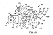
- an acetabular prosthesis 10 includes a modified hemispherical acetabular cup 12.
- the acetabular cup 12 is said to be "hemispherical" in that it is not a perfect hemisphere; but rather, it includes an arcuate portion 14 extending along the periphery thereof without extending beyond the hemisphere of the acetabular cup 12.
- the acetabular cup 12 is preferably constructed from any suitable biocompatible material, such as titanium, stainless steel, titanium alloy, cobalt-chrome-molybdenum alloy, and the like.
- acetabular cup 12 would normally also be associated with other components, such as a congruent shell or bearing liner (not shown) retained within the acetabular cup 12, via bone cement or a ring lock (not shown), which are not depicted for purposes of clarity.
- the acetabular cup 12 preferably includes a substantially concave inner surface 16 and a substantially convex outer surface 18, wherein the outer surface 18 is operable to be received in the acetabulum.
- the inner surface 16 may be either roughened or smooth, whereas the outer surface 18 may be smooth or roughened with a grit blast or a porous surface layer (not shown) to facilitate bone tissue in-growth.
- An area defining an optional receptacle or groove 20 is located in at least a portion of the outer surface 18 of the acetabular cup 12.
- the groove 20 may include tapered end portions 22, 24.
- the groove 20 is located in proximity to a peripheral surface of the acetabular cup 12, and generally in the superior and posterior region of the acetabular cup 12. The exact purpose of the groove 20 will be explained later in detail.
- the acetabular cup 12 may include at least one, and generally, a plurality of throughbores 26 located therein. It should be noted that the groove 20 is bisected by at least one of the throughbores 26.
- the throughbores 26 provide a number of functions, such as enabling fastening members (not shown) to pass through the acetabular cup 12. Additionally, the throughbores 26 provide for the infiltration of bone cement to improve adhesion, as well as providing for new bone tissue in-growth.
- At least one of the throughbores 28 includes a threaded surface 30 thereon for receiving an insertion instrument (not shown) for properly aligning the acetabular prosthesis 10 within the acetabulum.
- Throughbore 28 also includes a recessed area 28A which permits the insertion instrument (not shown) to securely engage the acetabular cup 12 and permits controlled rotation of same. It will be noted that any graft material and/or bone cement should preferably be placed into the acetabulum before securing the acetabular cup 12 thereto.
- the acetabular cup 12 preferably includes at least one, and more preferably, three substantially rigid attachment or extension members 32, 34, and 36 integrally formed with the acetabular cup 12 for fastening the acetabular prosthesis 10 to at least a portion of one or more surfaces of the pelvis (not shown), such as the ilium and/or the ischium.
- attachment member 32 is used for attachment to the ischium
- attachment members 34 and 36 are used for attachment to various surfaces of the ilium (e.g., anterior and posterior).
- Attachment member 32 is shown as being substantially triangularly shaped; however, it is envisioned that the shape may be altered to other configurations. It will be noted that attachment member 32 has two distinct portions, i.e., a first substantially curved portion 32A originating from, and contiguous with, the inner surface 16 of the acetabular cup 12, and a second substantially planar portion 32B extending out from, and angling away from, the first portion 32A.
- the curvature profile may be modified to meet any anatomical requirements.
- Attachment member 32 preferably includes at least one, and more preferably, a plurality of throughbores located therein.
- a throughbore 38 is provided in the curved portion 32A and another throughbore 40 is provided in the planar portion 32B.
- the throughbores 38, 40 provide a number of functions, such as enabling fastening members such as a surgical screw (not shown) to pass therethrough in order to allow the fastening member 32 to be secured to the ischium.
- Attachment member 34 is shown as being substantially rectangularly shaped; however, it is envisioned that the shape may be altered to other configurations. It will be noted that attachment member 34 has two distinct portions, i.e., a first substantially curved portion 34A originating from, and contiguous with, the inner surface 16 of the acetabular cup 12, and a second substantially planar portion 34B extending out from, and angling away from, the first portion 34A.
- the curvature profile may be modified to meet any anatomical requirements.
- Attachment member 34 preferably includes at least one, and more preferably, a plurality of throughbores 42 located therein.
- additional throughbores 42A and 42B are provided in the curved portion 34A.
- the throughbores 42, 42A, and 42B provide a number of functions, such as enabling fastening members such as a surgical screw (not shown) to pass therethrough in order to allow the fastening member 34 to be secured to at least a portion of a surface of the ilium.
- Attachment member 36 is also shown as being substantially rectangularly shaped; however, it is envisioned that the shape may be altered to other configurations. It will be noted that attachment member 36 also has two distinct portions, i.e., a first substantially curved portion 36A originating from, and contiguous with, the inner surface 16 of the acetabular cup 12, and a second substantially planar portion 36B extending out from, and angling away from, the first portion 36A. Again, the curvature profile may be modified to meet any anatomical requirements.
- Attachment member 36 preferably includes at least one, and more preferably, a plurality of throughbores 44 located therein.
- an additional throughbore 44A is provided in the curved portion 36A.
- the throughbores 44 and 44A provide a number of functions, such as enabling fastening members such as a surgical screw (not shown) to pass therethrough in order to allow the fastening member 36 to be secured to at least another portion of a surface of the ilium spaced away from attachment member 34.
- the installation of the acetabular prosthesis 10 would be accomplished in any number of ways, as are currently known in the art.
- the surgeon would surgically prepare the acetabulum and surrounding pelvic area to receive the acetabular prosthesis 10. This preparation would typically include removing any debris (e.g., bone fragments, bone cement) from the acetabulum.
- the surgeon would then install an allograft, if necessary, and install bone cement, if necessary, into the acetabulum.
- the acetabular cup 12 would then be received into, and anatomically aligned with, the acetabulum.
- At least one fastening member such as a surgical screw, would then be placed through one of the throughbores 26 and into the interior of acetabulum, thus securing the acetabular cup 12 to the acetabulum.
- the attachment members 32, 34, and 36 would then be secured to the ischium and ilium, respectively, with fastening members, such as surgical screws.
- the loading will be borne primarily by the allograft and/or bone cement material, as previously described. Therefore, it is desirable to have the surfaces of the acetabular prosthesis 10 actually abut against the respective surfaces of the acetabulum and/or the surrounding pelvic structures, as opposed to using allografts and bone cement to fill the gap therebetween. Because the acetabular prosthesis 10 is constructed of metallic material, it is much stronger than allografts and bone cement, and therefore is much more able to withstand the loads and forces associated with standing, walking, and running activities.
- the present invention may employ at least one augment or spacer member to compensate for the fact that the acetabulum and/or the surrounding pelvic structures may have defects therein which prevent the outer surface 18 of the acetabular cup 12 from contacting the surface of the acetabulum, and/or the outer surfaces 32C, 34C, and 36C, respectively, from contacting the respective surfaces of the pelvis, i.e., the ischium and the ilium.
- the spacer members are preferably constructed from any suitable biocompatible material, such as titanium, stainless steel, titanium alloy, cobalt-chrome-molybdenum alloy, etc. and is preferably made of the titanium alloy Ti-6AI-4V.
- acetabular spacer members 60, 62, and 64 for use with the outer surface 18 of the acetabular cup 12, according to the general teachings of the present invention, are shown. It should be noted that only one spacer member would generally be used at a time in practice; however, multiple spacer members may be used in some instances. For example, if there is a relatively small defect in the superior region of the acetabulum, acetabular spacer member 60 can be employed. If there is a larger defect, either acetabular spacer member 62 or 64 may be used. It is envisioned that either smaller and/or larger acetabular spacer members may also be employed with the present acetabular prosthesis.
- the acetabular spacer members 60, 62, and 64 may be substantially curved so that the lower surfaces 60A, 62A, and 64A, substantially conform to the curvature of the outer surface 18 of the acetabular cup 12. Additionally, the acetabular spacer members 60, 62, and 64 may include an area defining a substantially curved and raised appendage or ridge 66, 68, and 70 formed on the lower surface 60A, 62A, and 64A, respectively, thereof for mating, and more preferably, sliding engagement with the groove 20. Finally, each acetabular spacer member 60, 62, and 64 preferably has at least one throughbore 72. The throughbores 72 preferably include a threaded surface 74 thereon. It should be noted that the raised ridges 66, 68, and 70 are bisected by the respective throughbore 72.
- the purpose of the raised ridges 66, 68, and 70, respectively, is to allow the respective acetabular spacer member 60, 62, or 64 to slidingly mate with the groove 20 on the outer surface 18 of the acetabular cup 12.
- This allows the surgeon the option of positioning the respective acetabular spacer member 60, 62, or 64 practically anywhere along the length of the groove 20 to best deal with the particular acetabular defect in the superior-posterior region.
- the acetabular spacer member 60, 62, or 64 can slide in a superior-posterior direction with respect to the acetabulum. It is also envisioned that the acetabular spacer member 60, 62, or 64 can slide in a medial direction, as well.
- the surgeon can then secure the respective acetabular spacer member to the acetabular cup 12 by inserting a fastening member, such as a surgical screw, through one or more available throughbores 72 which generally aligns with one or more of the throughbores 26 which bisect the groove 20.
- the screw may extend upwardly through the acetabular cup 12 and into the respective acetabular spacer member, with the screw tip not extending past the upper surface of the respective acetabular spacer member.
- the modified acetabular prosthesis 10 can then be installed in the acetabulum, as previously described, such that the acetabular spacer member 60, 62, or 64 is disposed between the outer surface 18 of the acetabular cup 12 and the acetabulum.
- acetabular spacer members 60, 62, or 64 alone is sometimes not enough to address each and every particular clinical situation.
- the use of the acetabular spacer members 60, 62, or 64 may address the defect in the acetabulum, but it may not address a defect in the surrounding pelvic structures, or alternatively, the use of the acetabular spacer members 60, 62, or 64 may alter the attachment point of the attachment members 32, 34 or 36 such that an undesirable gap is created between the respective outer surfaces 32C, 34C, and 36C and the pelvis.
- the present invention employs at least one other augment or spacer member to compensate for the fact that the surrounding pelvic structures may have defects therein which prevent the outer surfaces 32C, 34C, and 36C of rigid attachment members 32, 34, and 36, respectively, from contacting the respective surfaces of the pelvis, i.e., the ischium and the ilium.
- attachment spacer members 100 and 102 for use with the attachment members 32, 34, and 36, respectively, according to the general teachings of the present invention, are shown. It should be noted that more than one attachment spacer member can be used at one time in practice. For example, if there is a relatively small defect in the surface of the ischium, or attachment member 32 can not abut it, an attachment spacer member 100 or 102 can be employed. If there is a defect in the surface of the ilium (either anterior and/or posterior), or attachment member 34 or 36 can not abut it, an attachment spacer member 100 or 102 can be employed. It is envisioned that either smaller and/or larger attachment spacer members may also be employed with the present invention.
- the attachment spacer members 100 and 102 generally have at least one flat surface 100A and 102A, respectively, for mating adjacently against the planar portions 32B, 34B, and 36B of attachment members 32, 34, and 36, respectively.
- the other surface of the attachment spacer members 100 and 102 may be either flat and parallel 100B or flat and non-parallel (i.e., inclined) 102B.
- Each attachment spacer member 100 and 102 may have at least one throughbore 104. At least one of the throughbores 104 generally includes a threaded surface 106 thereon. The surgeon can then secure the respective attachment spacer member 100 or 102 to the outer surface 32C, 34C, or 36C, respectively, by inserting a fastening member, such as a surgical screw, through one or more available throughbores 104 which preferably aligns with one or more of the throughbores 40, 42, 44, respectively, in planar portions 32B, 34B, or 36B, respectively.
- a fastening member such as a surgical screw
- the further modified acetabular prosthesis 10 then can be installed in the acetabulum, as previously described, such that the attachment spacer members 100 and/or 102 are disposed between the outer surface 32C, 34C, or 36C, respectively, of the planar portions 32B, 34B, or 36B, respectively, of the attachment members 32, 34, or 36, respectively, and the pelvis, i.e., the ischium and/or the ilium.
- two diagonally opposed and spaced throughbores 104 are used to attach the attachment spacer member 100 and 102 to the outer surface 32C, 34C, or 36C, respectively, of the planar portions 32B, 34B, or 36B, respectively, of the attachment members 32, 34, or 36, respectively, and the pelvis, i.e., the ischium and/or the ilium.
- Bone screws (not shown) can then be inserted through the two diagonally opposed throughbores 104, and the aligned one or more of the throughbores 40, 42, 44, respectively, to secure the attachment members 32, 34, or 36, respectively, to the pelvis.
- attachment spacer members 100 and/or 102 alone, instead of using them in conjunction with an acetabular spacer member 60, 62, or 64.
- the groove 20 is employed in the outer surface 18 of the acetabular cup 12, as opposed to a raised appendage or ridge which may interfere with the proper alignment of the acetabular cup 12, or might irritate the acetabulum.
- the acetabular prosthesis 10 may be implanted using any number of methods, the acetabular prosthesis 10 is generally implanted after employing a particular trialing prosthesis.
- the trialing acetabular prosthesis generally resembles the acetabular prosthesis 10, but may be constructed out of a less substantial material than the acetabular prosthesis 10.
- the trial acetabular prosthesis may also differ from the acetabular prosthesis 10 by not having a porous coat or as many throughbores.
- the trialing acetabular prosthesis allows the acetabular prosthesis to be placed in the acetabulum to assure a proper size and fit before attempting to secure the acetabular prosthesis 10 to the pelvic area.
- a trialing acetabular prosthesis allows the physician to determine the appropriate spacers, if necessary, or a slightly augmented orientation of the various attachment members 32, 34, and 36.
- trial attachment members may be bent or deflected to determine if the attachment members 32, 34, and 36 should also be bent before implantation.
- a trialing component be provided for the acetabular prosthesis 10, but a trial shell or bearing liner 200 may also be provided.
- the trial shell 200 may be associated with the acetabular prosthesis 10 after it has been implanted to trial the appropriate position of the prosthetic shell (at 320 in Figure 20) before implanting the prosthetic shell.
- the prosthetic shell substantially resembles the trial shell 200, save that the prosthetic shell is substantially solid and continuous.
- the trial shell 200 generally include a shell that is substantially congruent to the acetabular cup 12 of the acetabular prosthesis 10.
- the trial shell includes an exterior 201 that is substantially convex that is substantially congruent with the acetabular cup 12.
- the trial shell 200 also includes an internal or shell recess 202, which is designed to substantially mate with either the ball of a femoral prosthetic or the head of a natural femur.
- a surface or wall 203 Between the inner recess 202 and the exterior 201, and at a meridian of the trial shell 200, is a surface or wall 203.
- a raised ridge 203a may be provided on a portion of the wall 203.
- a trial track or trial slot 204 Formed in and along an arc of the exterior 201 is a trial track or trial slot 204.
- the slot 204 passes substantially through the trial shell 200 and provides a passage from the exterior 201 to the internal recess 202.
- the slot 204 may reach substantially from a first side 205 to a second side 206 of the interior recess 202.
- the slot 204 provides a channel that reaches substantially across the trial shell 200.
- the slot 204 generally defines a total arc about 60° to about 120°. Therefore, the trial shell 200 may have a range of motion of about 60° to about 120°. It will be understood that various different trial shells may include an arc having a different angle.
- the slot 204 is an orientation portion of the trial shell 200, as described further herein.
- the slot 204 provides an area for a trial screw 212 to be received.
- a depression or countersink 208 substantially surrounds the perimeter of the slot 204.
- the trial screw 212 would generally include a head portion 214 and a threaded shank 216.
- the head portion 214 may define a substantially arcuate top portion 218.
- the head portion 214 is substantially received or is nested in the countersink 208.
- the screw 212 would not interfere with a head or ball portion of a femur (illustrated in Figure 19a-19c) since the head 214 rests within the countersink 208.
- the shank portion 216 is received through the slot 204 and may be held in place with a lock ring 217 or similar appropriate device.
- the trial shell 200, trial screw 212, and lock ring 217 form an assembly easily manipulated by a physician and eliminates an non-affixed component during the procedure.
- the threaded shank 216 may engage the threads 30 of the throughbore 28.
- the trial screw 212 when received through the slot 204 and tightened into the threads 30, would substantially not interfere with the inner recess 202.
- the top portion 218 of the head 214 further defines the inner recess 202 or is substantially congruent therewith, such that when a head portion or ball portion of a hip prosthesis is inserted into the inner cup 202, the trial screw 212 does not interfere with movement of the head portion.
- the trial shell 200 may be affixed substantially fixed and motionless relative the acetabular cup 12. This is accomplished by passing the trial screw 212 through the slot 204 of the trial shell 200 and engaging the threads 30 with the trial screw 212. The trial screw 212 may then be tightened against the recess 208, formed in the trial shell 200, to hold the trial shell 200 in a predetermined selected position. In this position, the trial shell 200 is substantially immobile relative the acetabular cup 12. The trial screw 212 interacts with the threads 30 to provide an attachment or connection mechanism between the trial shell 200 and the acetabular cup 12. It will be understood, however, that other connection mechanisms may provide similar connections. For example a pin or removable rivet may be used to selectively fix the trial shell 200 in a selected orientation relative the acetabular cup 12.
- the trial screw 212 may be loosened so that the trial shell 200 may be moved or adjusted and then reaffixed by tightening the screw 212 against the recess 208 of the trial shell 200. It will be understood that other appropriate shapes or types of screws may be used as the trial screw 212. Furthermore, any appropriate tool may be used to manipulate the trial screw 212.
- the trial shell 200 may be positioned and fixed at a substantial plurality of orientations relative the acetabular prosthesis 10.
- a rim 240 of the acetabular cup 12 defines an acetabular cup plane A.
- the rim 203 of the trial shell 200 also defines a plane B.
- a third axis or axis of orientation C is defined by the shank 216 of the trial screw 212. It will be understood that the trial shell 200, when the trial screw 212 is loosened, may be moved along the slot 204 for its length and rotated substantially 360° around the trial screw 212.
- the various orientations of the trial shell 200 are relative the orientation axis C.
- the orientation axis C is also substantially defined by the throughbore 28 which is formed substantially at a pole of the acetabular cup 12.
- One exemplary position will allow a negative angle ⁇ , specifically illustrated in Figure 17a.
- the angles given are in reference to the relative orientation of the planes A and B when in a pelvis 300. Particularly, the relative orientation of the interior portion of the plane B relative to plane A. Therefore, when the angle ⁇ is negative the trial shell plane B is below acetabular cup plane A. In this exemplary position, the trial screw 212 may be tightened to hold the trial shell 200 in place.
- a separate or different exemplary orientation may provide a positive angle a.
- the trial shell 200 may have relative the acetabular prosthesis 10 by loosening the trial screw 212 and moving the trial shell 200 relative the acetabular prosthesis 10. This allows the trial shell 200 to be orientated for trialing of the femur before fixedly implanting the prosthetic shell into the acetabular cup 12 after implanting the acetabular prosthesis 10.
- an exemplary method for using this system as disclosed herein provides a method to both trial the acetabular prosthesis 10, with a trial acetabular prosthesis or protrusion cage, and to trial the trial shell 200 for the prosthetic liner 320.
- an acetabulum 302 is prepared as generally known in the art, and generally includes removing any extraneous cartilage, loose bone debris or other material that would interfere with the implantation of the acetabular prosthesis 10.
- a trial acetabular prosthesis or trial protrusio cage can be trialed in the prepared acetabulum 302.
- the trial acetabular prosthesis is substantially similar to the acetabular prosthesis 10 save that it may have a smooth outside as opposed to a porous coat and other minor differences.
- the trial acetabular prosthesis will help the physician determine the proper implant size and placement of any necessary spacers or if any of the attachment members need to be repositioned, as by bending, before implanting the acetabular prosthesis 10.
- the physician may also determine a proper orientation using the trial acetabular prosthesis which is then mimicked when implanting the acetabular prosthesis 10. Once the physician has trialed the placement of the acetabular prosthesis 10, the appropriate spacers may be assembled and the proper orientation of the acetabular prosthesis 10 is easily determined.
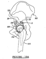
- the assembled components are implanted into the acetabulum 302 of the patient, including the acetabular prosthesis 10 in the appropriate orientation and the appropriate and necessary spacers, as illustrated in Figure 18.
- the acetabular prosthesis 10 may be implanted using any appropriate methods such as using fastening members such as screws, or other fixation means such as bone cement.
- the attachment members 32, 34, and 36 are also affixed to the appropriate portions of the illium 303 and ischium 304 of the pelvis 300.
- the trial shell 200 may be positioned in the acetabular cup 12 by placing the trial screw 212 through the slot 204 and engaging the threads 30 of the throughbore 28.
- the orientation axis C may be slightly different depending upon the individual into which the acetabular prosthesis 10 is implanted, the orientation axis C is generally does not lie on either the median plane or coronal plane of the patient.
- the trial shell 200 is oriented relative this orientation axis C by moving it along the slot 204 of the trial shell 200, as described above.
- a first orientation of the trial shell 200 is chosen.
- the physician implanting the acetabular prosthesis 10 chooses a first orientation by placing the trial shell 200 at a desired orientation relative the acetabular cup 12 and fixing it in place by tightening the trial screw 212 against the recess 208 of the trial shell 200. After this occurs, the physician can determine whether an appropriate orientation has been chosen to allow range of movement for the hip joint. This is done by placing the head 308 of the femur 310 in place in the interior recess 202.
- the femur 310 is then moved through an appropriate range of motion to determine if the stem or neck 312 of the femur 310 engages any portion of the trial shell 200. It is generally desired to have a low or substantially no dislocation force when the femur 310 is moved through a general range of motion. If such a force were to occur the head 308 may dislocate from the inner recess 202. It will be understood that the head 308 may be a prosthetic head, a natural head, or a femoral replacement.
- the femur 310 may first be moved to a natural or neutral position. With reference to Figure 19B, the femur may then be moved to about 90° of flexion and taken through a range of internal rotation. And finally with reference to Figures 19C, the femur may be moved to about 30° of extension and taken through a range of external rotation. It will be understood the femur 310 is generally moved fluidly and continuously from position to position. Also, a plurality of other specific positions may be trialed. In any of these positions, a contact between the femur 310 and the trial shall 200 may be felt or seen by the physician. Furthermore, a dislocation of the head form the trial shell 200 would also be ascertained.
- the physician may attempt a different position of the trial shell 200.
- the trial shell 200 may be moved by first loosening the trial screw 212 moving the trial shell 200 to a different orientation, exemplarily illustrated in Figure 17a or 17b, and retightening the trial screw 212 to hold the trial shell 200 substantially fixed in the new position.
- the physician may then trial the hip joint by moving the femur 310 again through a range of motion to determine whether any portion of the femur 310 engages a portion of the trial shell 200 or if the head 308 dislocates from the trial shell 200.
- the physician may then note the orientation and position of the trial shell 200. This may be done through any appropriate method, such as marking the orientation on the trial shell 200 or noting the orientation of the trial shell 200.
- the trial shell 200 may also include demarcations on the exterior 201. These demarcations may be noted when the orientation of the trial shell 200 is selected. Similar demarcations may be included on the exterior of the prosthetic shell 320 and may be used to match the orientation of the prosthetic shell 320 to the selected orientation. Alternatively the demarcations may provide a reference for placing the prosthetic shell 320.
- the femur 310 is again dislocated from the inner recess 202 and the trial screw 212 and trial shell 200 are removed from the acetabular prosthesis 10. This is performed by simply removing the trial screw 212 and then removing the trial shell 200 from the acetabular prosthesis 10.
- a prosthetic shell or liner 320 may be implanted into the acetabular prosthesis 10.
- the prosthetic shell 320 is placed into the acetabular prosthesis 10 according to the determined orientation of the trial shell 200. It will be understood, therefore, that the trial shell 200 and the prosthetic shell 320 generally are similar in size and shape.
- the trial shell 200 may differ if the differences are accounted for in the procedure, such as offset or roundness of the trial shell 200 compared to the prosthetic liner 320.
- the prosthetic shell 320 is then permanently affixed in place using an appropriate means, such as a bone cement.
- the bone cement substantially permanently affixes the prosthetic shell 320 in place, such that after the femur 310 is placed to engage the prosthetic shell 320, the shell 320 does not move.
- a proper orientation of the shell 320 may be determined before the shell 320 is implanted into the acetabular prosthesis 10.
- the trial shell 200 allows a selection of a proper orientation of the shell 320 using a removably fixation means, such as the trial screw 212. This allows the physician to trial several orientations of the trial shell 200 before permanently affixing, or substantially permanently affixing a shell 320 into the acetabular prosthesis. Therefore, the appropriate orientation of the shell can be determined more precisely and with substantially little error by using the trial shell 200.
Landscapes
- Health & Medical Sciences (AREA)
- Orthopedic Medicine & Surgery (AREA)
- Transplantation (AREA)
- Heart & Thoracic Surgery (AREA)
- Cardiology (AREA)
- Oral & Maxillofacial Surgery (AREA)
- Engineering & Computer Science (AREA)
- Biomedical Technology (AREA)
- Vascular Medicine (AREA)
- Life Sciences & Earth Sciences (AREA)
- Animal Behavior & Ethology (AREA)
- General Health & Medical Sciences (AREA)
- Public Health (AREA)
- Veterinary Medicine (AREA)
- Physical Education & Sports Medicine (AREA)
- Prostheses (AREA)
Applications Claiming Priority (2)
| Application Number | Priority Date | Filing Date | Title |
|---|---|---|---|
| US201485 | 1988-06-01 | ||
| US10/201,485 US7291177B2 (en) | 2001-02-23 | 2002-07-23 | Method and apparatus for acetabular reconstruction |
Publications (3)
| Publication Number | Publication Date |
|---|---|
| EP1384456A2 true EP1384456A2 (de) | 2004-01-28 |
| EP1384456A3 EP1384456A3 (de) | 2006-09-20 |
| EP1384456B1 EP1384456B1 (de) | 2018-01-31 |
Family
ID=30000089
Family Applications (1)
| Application Number | Title | Priority Date | Filing Date |
|---|---|---|---|
| EP03254588.1A Expired - Lifetime EP1384456B1 (de) | 2002-07-23 | 2003-07-23 | Acetabulum-Prothesesystem |
Country Status (2)
| Country | Link |
|---|---|
| US (1) | US7291177B2 (de) |
| EP (1) | EP1384456B1 (de) |
Cited By (13)
| Publication number | Priority date | Publication date | Assignee | Title |
|---|---|---|---|---|
| EP1532946A2 (de) * | 2001-02-23 | 2005-05-25 | Biomet Manufacturing Corp. | Verfahren und Vorrichtung zur Wiederherstellung der Hüftgelenkpfanne |
| US7291177B2 (en) | 2001-02-23 | 2007-11-06 | Biomet Manufacturing Corp. | Method and apparatus for acetabular reconstruction |
| EP2042129A1 (de) | 2007-09-27 | 2009-04-01 | DePuy Products, Inc. | Hüftgelenkprothese mit verstellbarer Vorderseite |
| US7764985B2 (en) | 2003-10-20 | 2010-07-27 | Smith & Nephew, Inc. | Surgical navigation system component fault interfaces and related processes |
| US7794467B2 (en) | 2003-11-14 | 2010-09-14 | Smith & Nephew, Inc. | Adjustable surgical cutting systems |
| US7862570B2 (en) | 2003-10-03 | 2011-01-04 | Smith & Nephew, Inc. | Surgical positioners |
| US8021432B2 (en) | 2005-12-05 | 2011-09-20 | Biomet Manufacturing Corp. | Apparatus for use of porous implants |
| US8109942B2 (en) | 2004-04-21 | 2012-02-07 | Smith & Nephew, Inc. | Computer-aided methods, systems, and apparatuses for shoulder arthroplasty |
| US8177788B2 (en) | 2005-02-22 | 2012-05-15 | Smith & Nephew, Inc. | In-line milling system |
| US8197550B2 (en) | 2005-04-21 | 2012-06-12 | Biomet Manufacturing Corp. | Method and apparatus for use of porous implants |
| US8266780B2 (en) | 2005-04-21 | 2012-09-18 | Biomet Manufacturing Corp. | Method and apparatus for use of porous implants |
| US8292967B2 (en) | 2005-04-21 | 2012-10-23 | Biomet Manufacturing Corp. | Method and apparatus for use of porous implants |
| US11103367B2 (en) | 2019-02-15 | 2021-08-31 | Encore Medical, L.P. | Acetabular liner |
Families Citing this family (105)
| Publication number | Priority date | Publication date | Assignee | Title |
|---|---|---|---|---|
| US8123814B2 (en) | 2001-02-23 | 2012-02-28 | Biomet Manufacturing Corp. | Method and appartus for acetabular reconstruction |
| US7892288B2 (en) | 2001-08-27 | 2011-02-22 | Zimmer Technology, Inc. | Femoral augments for use with knee joint prosthesis |
| US20040162619A1 (en) | 2001-08-27 | 2004-08-19 | Zimmer Technology, Inc. | Tibial augments for use with knee joint prostheses, method of implanting the tibial augment, and associated tools |
| US20030065397A1 (en) | 2001-08-27 | 2003-04-03 | Hanssen Arlen D. | Prosthetic implant support structure |
| USD684693S1 (en) | 2002-08-22 | 2013-06-18 | Zimmer, Inc. | Prosthetic implant support structure |
| GB0313444D0 (en) * | 2003-06-11 | 2003-07-16 | Midland Medical Technologies L | Modular dysplasia cup |
| US6944518B2 (en) * | 2003-09-18 | 2005-09-13 | Depuy Products, Inc. | Customized prosthesis and method of designing and manufacturing a customized prosthesis by utilizing computed tomography data |
| ES2302984T3 (es) * | 2003-09-27 | 2008-08-01 | AESCULAP AG & CO. KG | Procedimiento y dispositivo para determinar la movilidad de una protesis de articulacion de cadera. |
| US8175683B2 (en) * | 2003-12-30 | 2012-05-08 | Depuy Products, Inc. | System and method of designing and manufacturing customized instrumentation for accurate implantation of prosthesis by utilizing computed tomography data |
| US20050288793A1 (en) * | 2004-06-28 | 2005-12-29 | Howmedica Osteonics Corp. | Internal fixation element for hip acetabular shell |
| GB0420346D0 (en) * | 2004-09-13 | 2004-10-13 | Finsbury Dev Ltd | Tool |
| US8361113B2 (en) | 2006-02-03 | 2013-01-29 | Biomet Sports Medicine, Llc | Method and apparatus for coupling soft tissue to a bone |
| US8137382B2 (en) | 2004-11-05 | 2012-03-20 | Biomet Sports Medicine, Llc | Method and apparatus for coupling anatomical features |
| US8298262B2 (en) | 2006-02-03 | 2012-10-30 | Biomet Sports Medicine, Llc | Method for tissue fixation |
| US7601165B2 (en) | 2006-09-29 | 2009-10-13 | Biomet Sports Medicine, Llc | Method and apparatus for forming a self-locking adjustable suture loop |
| US8303604B2 (en) | 2004-11-05 | 2012-11-06 | Biomet Sports Medicine, Llc | Soft tissue repair device and method |
| US7749250B2 (en) | 2006-02-03 | 2010-07-06 | Biomet Sports Medicine, Llc | Soft tissue repair assembly and associated method |
| US7909851B2 (en) | 2006-02-03 | 2011-03-22 | Biomet Sports Medicine, Llc | Soft tissue repair device and associated methods |
| US9017381B2 (en) | 2007-04-10 | 2015-04-28 | Biomet Sports Medicine, Llc | Adjustable knotless loops |
| US8088130B2 (en) | 2006-02-03 | 2012-01-03 | Biomet Sports Medicine, Llc | Method and apparatus for coupling soft tissue to a bone |
| US8128658B2 (en) | 2004-11-05 | 2012-03-06 | Biomet Sports Medicine, Llc | Method and apparatus for coupling soft tissue to bone |
| US9801708B2 (en) | 2004-11-05 | 2017-10-31 | Biomet Sports Medicine, Llc | Method and apparatus for coupling soft tissue to a bone |
| US7905904B2 (en) | 2006-02-03 | 2011-03-15 | Biomet Sports Medicine, Llc | Soft tissue repair device and associated methods |
| US8118836B2 (en) | 2004-11-05 | 2012-02-21 | Biomet Sports Medicine, Llc | Method and apparatus for coupling soft tissue to a bone |
| US20060190089A1 (en) * | 2005-02-18 | 2006-08-24 | Howmedica Osteonics Corp. | Internal adaptor for hip acetabular cage |
| US8066778B2 (en) | 2005-04-21 | 2011-11-29 | Biomet Manufacturing Corp. | Porous metal cup with cobalt bearing surface |
| US20070106392A1 (en) * | 2005-11-08 | 2007-05-10 | Howmedica Osteonics Corp. | Acetabular cup locking mechanism |
| US9078644B2 (en) | 2006-09-29 | 2015-07-14 | Biomet Sports Medicine, Llc | Fracture fixation device |
| US11311287B2 (en) | 2006-02-03 | 2022-04-26 | Biomet Sports Medicine, Llc | Method for tissue fixation |
| US8562645B2 (en) | 2006-09-29 | 2013-10-22 | Biomet Sports Medicine, Llc | Method and apparatus for forming a self-locking adjustable loop |
| US11259792B2 (en) | 2006-02-03 | 2022-03-01 | Biomet Sports Medicine, Llc | Method and apparatus for coupling anatomical features |
| US9468433B2 (en) | 2006-02-03 | 2016-10-18 | Biomet Sports Medicine, Llc | Method and apparatus for forming a self-locking adjustable loop |
| US8801783B2 (en) | 2006-09-29 | 2014-08-12 | Biomet Sports Medicine, Llc | Prosthetic ligament system for knee joint |
| US9149267B2 (en) | 2006-02-03 | 2015-10-06 | Biomet Sports Medicine, Llc | Method and apparatus for coupling soft tissue to a bone |
| US8968364B2 (en) | 2006-02-03 | 2015-03-03 | Biomet Sports Medicine, Llc | Method and apparatus for fixation of an ACL graft |
| US8597327B2 (en) | 2006-02-03 | 2013-12-03 | Biomet Manufacturing, Llc | Method and apparatus for sternal closure |
| US10517587B2 (en) | 2006-02-03 | 2019-12-31 | Biomet Sports Medicine, Llc | Method and apparatus for forming a self-locking adjustable loop |
| US8652171B2 (en) | 2006-02-03 | 2014-02-18 | Biomet Sports Medicine, Llc | Method and apparatus for soft tissue fixation |
| US8562647B2 (en) | 2006-09-29 | 2013-10-22 | Biomet Sports Medicine, Llc | Method and apparatus for securing soft tissue to bone |
| US7635447B2 (en) * | 2006-02-17 | 2009-12-22 | Biomet Manufacturing Corp. | Method and apparatus for forming porous metal implants |
| US20150335438A1 (en) | 2006-02-27 | 2015-11-26 | Biomet Manufacturing, Llc. | Patient-specific augments |
| US8608749B2 (en) | 2006-02-27 | 2013-12-17 | Biomet Manufacturing, Llc | Patient-specific acetabular guides and associated instruments |
| US8603180B2 (en) | 2006-02-27 | 2013-12-10 | Biomet Manufacturing, Llc | Patient-specific acetabular alignment guides |
| US8591516B2 (en) | 2006-02-27 | 2013-11-26 | Biomet Manufacturing, Llc | Patient-specific orthopedic instruments |
| US9173661B2 (en) | 2006-02-27 | 2015-11-03 | Biomet Manufacturing, Llc | Patient specific alignment guide with cutting surface and laser indicator |
| US8407067B2 (en) | 2007-04-17 | 2013-03-26 | Biomet Manufacturing Corp. | Method and apparatus for manufacturing an implant |
| US9113971B2 (en) | 2006-02-27 | 2015-08-25 | Biomet Manufacturing, Llc | Femoral acetabular impingement guide |
| US9339278B2 (en) | 2006-02-27 | 2016-05-17 | Biomet Manufacturing, Llc | Patient-specific acetabular guides and associated instruments |
| US9345548B2 (en) | 2006-02-27 | 2016-05-24 | Biomet Manufacturing, Llc | Patient-specific pre-operative planning |
| US8535387B2 (en) | 2006-02-27 | 2013-09-17 | Biomet Manufacturing, Llc | Patient-specific tools and implants |
| US8568487B2 (en) | 2006-02-27 | 2013-10-29 | Biomet Manufacturing, Llc | Patient-specific hip joint devices |
| US9907659B2 (en) | 2007-04-17 | 2018-03-06 | Biomet Manufacturing, Llc | Method and apparatus for manufacturing an implant |
| US9289253B2 (en) | 2006-02-27 | 2016-03-22 | Biomet Manufacturing, Llc | Patient-specific shoulder guide |
| US9918740B2 (en) | 2006-02-27 | 2018-03-20 | Biomet Manufacturing, Llc | Backup surgical instrument system and method |
| US8092465B2 (en) | 2006-06-09 | 2012-01-10 | Biomet Manufacturing Corp. | Patient specific knee alignment guide and associated method |
| US8608748B2 (en) | 2006-02-27 | 2013-12-17 | Biomet Manufacturing, Llc | Patient specific guides |
| US10278711B2 (en) | 2006-02-27 | 2019-05-07 | Biomet Manufacturing, Llc | Patient-specific femoral guide |
| US8377066B2 (en) | 2006-02-27 | 2013-02-19 | Biomet Manufacturing Corp. | Patient-specific elbow guides and associated methods |
| US7967868B2 (en) | 2007-04-17 | 2011-06-28 | Biomet Manufacturing Corp. | Patient-modified implant and associated method |
| WO2007108848A1 (en) * | 2006-03-20 | 2007-09-27 | Smith & Nephew, Inc. | Acetabular cup assembly for multiple bearing materials |
| US9005302B2 (en) * | 2006-04-19 | 2015-04-14 | Peter Brehm Gmbh | Modular hip implant |
| US9795399B2 (en) | 2006-06-09 | 2017-10-24 | Biomet Manufacturing, Llc | Patient-specific knee alignment guide and associated method |
| US8672969B2 (en) | 2006-09-29 | 2014-03-18 | Biomet Sports Medicine, Llc | Fracture fixation device |
| US11259794B2 (en) | 2006-09-29 | 2022-03-01 | Biomet Sports Medicine, Llc | Method for implanting soft tissue |
| US9161844B2 (en) | 2007-04-03 | 2015-10-20 | Finsbury (Development) Limited | Method of using a trial acetabular cup for insertion of an acetabular prosthesis |
| US7682399B2 (en) * | 2007-06-06 | 2010-03-23 | Howmedica Osteonics Corp. | Acetabular shell |
| US7993408B2 (en) * | 2008-02-12 | 2011-08-09 | Biomet Manufacturing Corp. | Acetabular cup having an adjustable modular augment |
| GB0804998D0 (en) * | 2008-03-18 | 2008-04-16 | Depuy Ireland Ltd | A cup component of an orthopaedic joint prosthesis |
| US8118868B2 (en) * | 2008-04-22 | 2012-02-21 | Biomet Manufacturing Corp. | Method and apparatus for attaching soft tissue to an implant |
| US20090265015A1 (en) * | 2008-04-22 | 2009-10-22 | Biomet Manufacturing Corp. | Method And Apparatus For Attaching Soft Tissue To Bone |
| US7985260B2 (en) | 2008-06-30 | 2011-07-26 | Depuy Products, Inc. | Acetabular prosthesis system |
| RU2011137986A (ru) | 2009-02-24 | 2013-04-10 | Смит Энд Нефью, Инк. | Способ и устройство для операций при семороацетабулярном конфликте |
| US8383033B2 (en) * | 2009-10-08 | 2013-02-26 | Biomet Manufacturing Corp. | Method of bonding porous metal to metal substrates |
| US20120179270A1 (en) * | 2010-03-10 | 2012-07-12 | Russell Nevins | Low stress multiple fixation acetabular component |
| RU2012157648A (ru) | 2010-06-08 | 2014-07-20 | Смит Энд Нефью, Инк. | Компонент имплантата и способ имплантации |
| US8828089B1 (en) | 2010-07-12 | 2014-09-09 | Howmedica Osteonics Corp. | Augmenting an acetabular implant site |
| EP2608746B1 (de) * | 2010-08-26 | 2020-06-24 | Smith & Nephew, Inc. | Instrumente zur verwendung in eingriffen zur behandlung von femoro-acetabulärem impingement |
| US9271744B2 (en) * | 2010-09-29 | 2016-03-01 | Biomet Manufacturing, Llc | Patient-specific guide for partial acetabular socket replacement |
| US9968376B2 (en) | 2010-11-29 | 2018-05-15 | Biomet Manufacturing, Llc | Patient-specific orthopedic instruments |
| US9023112B2 (en) | 2011-02-24 | 2015-05-05 | Depuy (Ireland) | Maintaining proper mechanics THA |
| US9241745B2 (en) | 2011-03-07 | 2016-01-26 | Biomet Manufacturing, Llc | Patient-specific femoral version guide |
| JP6211514B2 (ja) | 2011-06-03 | 2017-10-11 | スミス アンド ネフュー インコーポレイテッド | 患者に適合した特徴を備える補綴ガイド |
| US8597365B2 (en) * | 2011-08-04 | 2013-12-03 | Biomet Manufacturing, Llc | Patient-specific pelvic implants for acetabular reconstruction |
| US9066734B2 (en) | 2011-08-31 | 2015-06-30 | Biomet Manufacturing, Llc | Patient-specific sacroiliac guides and associated methods |
| US9386993B2 (en) | 2011-09-29 | 2016-07-12 | Biomet Manufacturing, Llc | Patient-specific femoroacetabular impingement instruments and methods |
| US9357991B2 (en) | 2011-11-03 | 2016-06-07 | Biomet Sports Medicine, Llc | Method and apparatus for stitching tendons |
| US9381013B2 (en) | 2011-11-10 | 2016-07-05 | Biomet Sports Medicine, Llc | Method for coupling soft tissue to a bone |
| US9357992B2 (en) | 2011-11-10 | 2016-06-07 | Biomet Sports Medicine, Llc | Method for coupling soft tissue to a bone |
| US9668745B2 (en) * | 2011-12-19 | 2017-06-06 | Depuy Ireland Unlimited Company | Anatomical concentric spheres THA |
| US8858645B2 (en) | 2012-06-21 | 2014-10-14 | DePuy Synthes Products, LLC | Constrained mobile bearing hip assembly |
| KR101396378B1 (ko) | 2012-12-18 | 2014-05-20 | 주식회사 코렌텍 | 인공고관절용 비구컵 |
| PL2764848T3 (pl) | 2013-02-08 | 2017-02-28 | Waldemar Link Gmbh & Co. Kg | Endoproteza do częściowego zastąpienia ludzkiej kości miednicznej |
| US9918827B2 (en) | 2013-03-14 | 2018-03-20 | Biomet Sports Medicine, Llc | Scaffold for spring ligament repair |
| US9820868B2 (en) | 2015-03-30 | 2017-11-21 | Biomet Manufacturing, Llc | Method and apparatus for a pin apparatus |
| US10226262B2 (en) | 2015-06-25 | 2019-03-12 | Biomet Manufacturing, Llc | Patient-specific humeral guide designs |
| US10568647B2 (en) | 2015-06-25 | 2020-02-25 | Biomet Manufacturing, Llc | Patient-specific humeral guide designs |
| US10456262B2 (en) | 2016-08-02 | 2019-10-29 | Howmedica Osteonics Corp. | Patient-specific implant flanges with bone side porous ridges |
| CN107049559B (zh) * | 2016-11-30 | 2019-01-08 | 北京爱康宜诚医疗器材有限公司 | 髋臼周围假体结构 |
| JP6916290B2 (ja) | 2017-01-20 | 2021-08-11 | バイオメット マニュファクチャリング,リミティド ライアビリティ カンパニー | モジュール式増強コンポーネント |
| US10722310B2 (en) | 2017-03-13 | 2020-07-28 | Zimmer Biomet CMF and Thoracic, LLC | Virtual surgery planning system and method |
| US10751186B2 (en) | 2017-09-12 | 2020-08-25 | Zimmer, Inc. | Methods for attaching acetabular augments together or to acetabular shells |
| US11369476B2 (en) | 2018-07-11 | 2022-06-28 | Smith & Nephew, Inc. | Flexible acetabular implant |
| CN112043464B (zh) * | 2020-08-04 | 2023-08-04 | 北京市春立正达医疗器械股份有限公司 | 髋臼假体及髋关节假体 |
| US11857423B2 (en) | 2021-11-16 | 2024-01-02 | Arthrology Consulting, Llc | Off-center liner for acetabular cup |
| US12042390B2 (en) | 2022-05-10 | 2024-07-23 | Depuy Ireland Unlimited Company | Acetabular prosthesis with adjustable acetabular cup cages |
Citations (3)
| Publication number | Priority date | Publication date | Assignee | Title |
|---|---|---|---|---|
| EP0807426A2 (de) * | 1996-05-17 | 1997-11-19 | JOHNSON & JOHNSON PROFESSIONAL Inc. | Hüftgelenkpfannen-Probeprothese |
| EP1082949A1 (de) * | 1999-09-09 | 2001-03-14 | LIMA Lto SpA | Gelenkpfannenprothese für die Hüfte |
| US6416553B1 (en) * | 1999-03-31 | 2002-07-09 | Biomet, Inc. | Method and apparatus for providing a modular acetabular prosthesis |
Family Cites Families (31)
| Publication number | Priority date | Publication date | Assignee | Title |
|---|---|---|---|---|
| FR2148322B1 (de) | 1971-07-22 | 1975-02-07 | Proteor Sa | |
| US4135517A (en) | 1977-07-21 | 1979-01-23 | Minnesota Mining And Manufacturing Company | Femoral prosthesis trial fitting device |
| DE3205526A1 (de) | 1982-02-12 | 1983-09-01 | Mecron Medizinische Produkte Gmbh, 1000 Berlin | Schablone zum plazieren von aufnahmeloechern im hueftgelenksbereich und zugehoeriger korb |
| US4978356A (en) | 1983-03-08 | 1990-12-18 | Joint Medical Products Corporation | Ball and socket bearing for artificial joint |
| US4795469A (en) | 1986-07-23 | 1989-01-03 | Indong Oh | Threaded acetabular cup and method |
| DE8714635U1 (de) | 1987-11-03 | 1987-12-17 | Waldemar Link Gmbh & Co, 2000 Hamburg | Hüftgelenk-Pfannenprothese |
| CH673766A5 (de) | 1988-03-01 | 1990-04-12 | Sulzer Ag | |
| US4892549B1 (en) | 1989-01-31 | 1999-10-05 | Stryker Corp | Dual-radius acetubular cup component |
| US5156626A (en) | 1990-06-29 | 1992-10-20 | Zimmer, Inc. | Set of provisional prosthesis instrumentation |
| US5176711A (en) | 1991-03-06 | 1993-01-05 | Grimes James B | Acetabular revision system |
| DE9111221U1 (de) | 1991-09-10 | 1991-10-24 | Howmedica GmbH, 2314 Schönkirchen | Endoprothese für karzinomgeschädigte Hüftknochen |
| DE4133433C1 (en) | 1991-10-09 | 1993-05-19 | S + G Implants Gmbh, 2400 Luebeck, De | Hip region pelvic joint prosthesis - has through bores in metal outer shell and coacting intermediate member for anchoring |
| EP0551794B1 (de) | 1992-01-16 | 1996-01-24 | SULZER Medizinaltechnik AG | Zweiteilige Hüftgelenkpfanne |
| EP0554210B1 (de) | 1992-01-29 | 1997-06-04 | Sulzer Orthopädie AG | Bausatz für eine künstliche Hüftgelenkspfanne |
| ATE146668T1 (de) | 1992-04-03 | 1997-01-15 | Sulzer Orthopaedie Ag | Aussenschale für eine künstliche hüftgelenkspfanne |
| US5326368A (en) | 1992-09-22 | 1994-07-05 | Howmedica, Inc. | Modular acetabular cup |
| US5507824A (en) | 1993-02-23 | 1996-04-16 | Lennox; Dennis W. | Adjustable prosthetic socket component, for articulating anatomical joints |
| US5702477A (en) | 1996-05-09 | 1997-12-30 | Osteonics Corp. | Acetabular shell with supplemental support and method |
| US5658348A (en) | 1996-09-09 | 1997-08-19 | Bristol-Myers Squibb Company | Acetabular implant with threaded liner and locking ring |
| US5931870A (en) | 1996-10-09 | 1999-08-03 | Smith & Nephew, Inc. | Acetabular ring prosthesis with reinforcement buttress |
| US5871548A (en) | 1996-12-07 | 1999-02-16 | Johnson & Johnson Professional, Inc. | Modular acetabular reinforcement system |
| AU1582499A (en) | 1997-10-31 | 1999-05-24 | Midwest Orthopaedic Research Foundation | Acetabular cup prosthesis with extension for deficient acetabulum |
| FR2775586B1 (fr) | 1998-03-03 | 2000-06-30 | Tornier Sa | Implant acetabulaire ou cotyloidien modulaire |
| FR2783703B1 (fr) | 1998-09-24 | 2001-02-09 | Philippe Bauchu | Calotte d'ancrage acetabulaire |
| US6340370B1 (en) * | 1999-03-10 | 2002-01-22 | Sulzer Orthopedics Ltd. | Modular set of an outer shell for an artificial hip joint cup |
| DE10036987A1 (de) | 2000-07-29 | 2002-02-07 | Klaus Draenert | Modularer Pfannenersatz |
| US6458161B1 (en) | 2001-02-23 | 2002-10-01 | Biomet, Inc. | Method and apparatus for acetabular reconstruction |
| US7291177B2 (en) | 2001-02-23 | 2007-11-06 | Biomet Manufacturing Corp. | Method and apparatus for acetabular reconstruction |
| US6908486B2 (en) * | 2002-01-25 | 2005-06-21 | Mayo Foundation For Medical Education And Research | Modular acetabular anti-protrusio cage and porous ingrowth cup combination |
| US7179297B2 (en) * | 2002-09-17 | 2007-02-20 | Smith & Nephew, Inc. | Combined bipolar and unipolar trials |
| US6926740B2 (en) | 2002-12-13 | 2005-08-09 | Depuy Products, Inc. | Modular orthopaedic implant apparatus and method |
-
2002
- 2002-07-23 US US10/201,485 patent/US7291177B2/en not_active Expired - Lifetime
-
2003
- 2003-07-23 EP EP03254588.1A patent/EP1384456B1/de not_active Expired - Lifetime
Patent Citations (3)
| Publication number | Priority date | Publication date | Assignee | Title |
|---|---|---|---|---|
| EP0807426A2 (de) * | 1996-05-17 | 1997-11-19 | JOHNSON & JOHNSON PROFESSIONAL Inc. | Hüftgelenkpfannen-Probeprothese |
| US6416553B1 (en) * | 1999-03-31 | 2002-07-09 | Biomet, Inc. | Method and apparatus for providing a modular acetabular prosthesis |
| EP1082949A1 (de) * | 1999-09-09 | 2001-03-14 | LIMA Lto SpA | Gelenkpfannenprothese für die Hüfte |
Cited By (17)
| Publication number | Priority date | Publication date | Assignee | Title |
|---|---|---|---|---|
| EP1532946A3 (de) * | 2001-02-23 | 2006-09-27 | Biomet Manufacturing Corp. | Verfahren und Vorrichtung zur Wiederherstellung der Hüftgelenkpfanne |
| US7291177B2 (en) | 2001-02-23 | 2007-11-06 | Biomet Manufacturing Corp. | Method and apparatus for acetabular reconstruction |
| EP1532946A2 (de) * | 2001-02-23 | 2005-05-25 | Biomet Manufacturing Corp. | Verfahren und Vorrichtung zur Wiederherstellung der Hüftgelenkpfanne |
| US7713306B2 (en) | 2001-02-23 | 2010-05-11 | Biomet Manufacturing Corp. | Method and apparatus for acetabular reconstruction |
| US7862570B2 (en) | 2003-10-03 | 2011-01-04 | Smith & Nephew, Inc. | Surgical positioners |
| US7764985B2 (en) | 2003-10-20 | 2010-07-27 | Smith & Nephew, Inc. | Surgical navigation system component fault interfaces and related processes |
| US7794467B2 (en) | 2003-11-14 | 2010-09-14 | Smith & Nephew, Inc. | Adjustable surgical cutting systems |
| US8109942B2 (en) | 2004-04-21 | 2012-02-07 | Smith & Nephew, Inc. | Computer-aided methods, systems, and apparatuses for shoulder arthroplasty |
| US8177788B2 (en) | 2005-02-22 | 2012-05-15 | Smith & Nephew, Inc. | In-line milling system |
| US8266780B2 (en) | 2005-04-21 | 2012-09-18 | Biomet Manufacturing Corp. | Method and apparatus for use of porous implants |
| US8197550B2 (en) | 2005-04-21 | 2012-06-12 | Biomet Manufacturing Corp. | Method and apparatus for use of porous implants |
| US8292967B2 (en) | 2005-04-21 | 2012-10-23 | Biomet Manufacturing Corp. | Method and apparatus for use of porous implants |
| US8021432B2 (en) | 2005-12-05 | 2011-09-20 | Biomet Manufacturing Corp. | Apparatus for use of porous implants |
| EP2042129A1 (de) | 2007-09-27 | 2009-04-01 | DePuy Products, Inc. | Hüftgelenkprothese mit verstellbarer Vorderseite |
| US8808390B2 (en) | 2007-09-27 | 2014-08-19 | DePuy Synthes Products, LLC | Acetabular prosthesis having an orientable face |
| EP2772229A1 (de) * | 2007-09-27 | 2014-09-03 | DePuy Products, Inc. | Hüftgelenkprothese mit verstellbarer Vorderseite |
| US11103367B2 (en) | 2019-02-15 | 2021-08-31 | Encore Medical, L.P. | Acetabular liner |
Also Published As
| Publication number | Publication date |
|---|---|
| US20030212459A1 (en) | 2003-11-13 |
| US7291177B2 (en) | 2007-11-06 |
| EP1384456A3 (de) | 2006-09-20 |
| EP1384456B1 (de) | 2018-01-31 |
Similar Documents
| Publication | Publication Date | Title |
|---|---|---|
| EP1384456B1 (de) | Acetabulum-Prothesesystem | |
| US7713306B2 (en) | Method and apparatus for acetabular reconstruction | |
| US9375316B2 (en) | Method and apparatus for acetabular reconstruction | |
| US6458161B1 (en) | Method and apparatus for acetabular reconstruction | |
| US6840959B2 (en) | Pelvic prosthesis plus methods and tools for implantation | |
| AU2011224714B2 (en) | Interlocking reverse hip and revision prosthesis | |
| EP1402854B1 (de) | Humerusprothese der umgekehrten Bauart | |
| CN102438554B (zh) | 髋臼杯 | |
| US20120016486A1 (en) | Implant components and methods | |
| US20060217815A1 (en) | Modular prosthetic head having a flat portion to be implanted into a constrained liner | |
| US20110264232A1 (en) | Acetabular Prosthesis System | |
| US20110054628A1 (en) | Reflex fixation geometry revision and reconstruction system reverse articulation | |
| US20060190089A1 (en) | Internal adaptor for hip acetabular cage | |
| US20140156011A1 (en) | Modified Reverse Joint and Revision Prosthesis | |
| AU2014221316B2 (en) | Acetabular prosthesis system |
Legal Events
| Date | Code | Title | Description |
|---|---|---|---|
| PUAI | Public reference made under article 153(3) epc to a published international application that has entered the european phase |
Free format text: ORIGINAL CODE: 0009012 |
|
| AK | Designated contracting states |
Kind code of ref document: A2 Designated state(s): AT BE BG CH CY CZ DE DK EE ES FI FR GB GR HU IE IT LI LU MC NL PT RO SE SI SK TR |
|
| AX | Request for extension of the european patent |
Extension state: AL LT LV MK |
|
| RIC1 | Information provided on ipc code assigned before grant |
Ipc: A61F 2/30 20060101ALI20060524BHEP Ipc: A61F 2/46 20060101AFI20031126BHEP Ipc: A61F 2/34 20060101ALI20060524BHEP |
|
| PUAL | Search report despatched |
Free format text: ORIGINAL CODE: 0009013 |
|
| AK | Designated contracting states |
Kind code of ref document: A3 Designated state(s): AT BE BG CH CY CZ DE DK EE ES FI FR GB GR HU IE IT LI LU MC NL PT RO SE SI SK TR |
|
| AX | Request for extension of the european patent |
Extension state: AL LT LV MK |
|
| 17P | Request for examination filed |
Effective date: 20070314 |
|
| AKX | Designation fees paid |
Designated state(s): AT BE BG CH CY CZ DE DK EE ES FI FR GB GR HU IE IT LI LU MC NL PT RO SE SI SK TR |
|
| 17Q | First examination report despatched |
Effective date: 20110303 |
|
| GRAP | Despatch of communication of intention to grant a patent |
Free format text: ORIGINAL CODE: EPIDOSNIGR1 |
|
| INTG | Intention to grant announced |
Effective date: 20170810 |
|
| GRAS | Grant fee paid |
Free format text: ORIGINAL CODE: EPIDOSNIGR3 |
|
| GRAA | (expected) grant |
Free format text: ORIGINAL CODE: 0009210 |
|
| AK | Designated contracting states |
Kind code of ref document: B1 Designated state(s): AT BE BG CH CY CZ DE DK EE ES FI FR GB GR HU IE IT LI LU MC NL PT RO SE SI SK TR |
|
| REG | Reference to a national code |
Ref country code: GB Ref legal event code: FG4D Ref country code: CH Ref legal event code: EP |
|
| REG | Reference to a national code |
Ref country code: AT Ref legal event code: REF Ref document number: 966670 Country of ref document: AT Kind code of ref document: T Effective date: 20180215 Ref country code: CH Ref legal event code: NV Representative=s name: MICHELI AND CIE SA, CH |
|
| REG | Reference to a national code |
Ref country code: IE Ref legal event code: FG4D |
|
| REG | Reference to a national code |
Ref country code: DE Ref legal event code: R096 Ref document number: 60350953 Country of ref document: DE |
|
| REG | Reference to a national code |
Ref country code: NL Ref legal event code: MP Effective date: 20180131 |
|
| REG | Reference to a national code |
Ref country code: AT Ref legal event code: MK05 Ref document number: 966670 Country of ref document: AT Kind code of ref document: T Effective date: 20180131 |
|
| PG25 | Lapsed in a contracting state [announced via postgrant information from national office to epo] |
Ref country code: ES Free format text: LAPSE BECAUSE OF FAILURE TO SUBMIT A TRANSLATION OF THE DESCRIPTION OR TO PAY THE FEE WITHIN THE PRESCRIBED TIME-LIMIT Effective date: 20180131 Ref country code: NL Free format text: LAPSE BECAUSE OF FAILURE TO SUBMIT A TRANSLATION OF THE DESCRIPTION OR TO PAY THE FEE WITHIN THE PRESCRIBED TIME-LIMIT Effective date: 20180131 Ref country code: FI Free format text: LAPSE BECAUSE OF FAILURE TO SUBMIT A TRANSLATION OF THE DESCRIPTION OR TO PAY THE FEE WITHIN THE PRESCRIBED TIME-LIMIT Effective date: 20180131 |
|
| PG25 | Lapsed in a contracting state [announced via postgrant information from national office to epo] |
Ref country code: GR Free format text: LAPSE BECAUSE OF FAILURE TO SUBMIT A TRANSLATION OF THE DESCRIPTION OR TO PAY THE FEE WITHIN THE PRESCRIBED TIME-LIMIT Effective date: 20180501 Ref country code: SE Free format text: LAPSE BECAUSE OF FAILURE TO SUBMIT A TRANSLATION OF THE DESCRIPTION OR TO PAY THE FEE WITHIN THE PRESCRIBED TIME-LIMIT Effective date: 20180131 Ref country code: AT Free format text: LAPSE BECAUSE OF FAILURE TO SUBMIT A TRANSLATION OF THE DESCRIPTION OR TO PAY THE FEE WITHIN THE PRESCRIBED TIME-LIMIT Effective date: 20180131 Ref country code: BG Free format text: LAPSE BECAUSE OF FAILURE TO SUBMIT A TRANSLATION OF THE DESCRIPTION OR TO PAY THE FEE WITHIN THE PRESCRIBED TIME-LIMIT Effective date: 20180430 |
|
| PG25 | Lapsed in a contracting state [announced via postgrant information from national office to epo] |
Ref country code: RO Free format text: LAPSE BECAUSE OF FAILURE TO SUBMIT A TRANSLATION OF THE DESCRIPTION OR TO PAY THE FEE WITHIN THE PRESCRIBED TIME-LIMIT Effective date: 20180131 Ref country code: EE Free format text: LAPSE BECAUSE OF FAILURE TO SUBMIT A TRANSLATION OF THE DESCRIPTION OR TO PAY THE FEE WITHIN THE PRESCRIBED TIME-LIMIT Effective date: 20180131 |
|
| REG | Reference to a national code |
Ref country code: DE Ref legal event code: R097 Ref document number: 60350953 Country of ref document: DE |
|
| PG25 | Lapsed in a contracting state [announced via postgrant information from national office to epo] |
Ref country code: CZ Free format text: LAPSE BECAUSE OF FAILURE TO SUBMIT A TRANSLATION OF THE DESCRIPTION OR TO PAY THE FEE WITHIN THE PRESCRIBED TIME-LIMIT Effective date: 20180131 Ref country code: DK Free format text: LAPSE BECAUSE OF FAILURE TO SUBMIT A TRANSLATION OF THE DESCRIPTION OR TO PAY THE FEE WITHIN THE PRESCRIBED TIME-LIMIT Effective date: 20180131 Ref country code: SK Free format text: LAPSE BECAUSE OF FAILURE TO SUBMIT A TRANSLATION OF THE DESCRIPTION OR TO PAY THE FEE WITHIN THE PRESCRIBED TIME-LIMIT Effective date: 20180131 |
|
| PLBE | No opposition filed within time limit |
Free format text: ORIGINAL CODE: 0009261 |
|
| STAA | Information on the status of an ep patent application or granted ep patent |
Free format text: STATUS: NO OPPOSITION FILED WITHIN TIME LIMIT |
|
| 26N | No opposition filed |
Effective date: 20181102 |
|
| REG | Reference to a national code |
Ref country code: DE Ref legal event code: R119 Ref document number: 60350953 Country of ref document: DE |
|
| PG25 | Lapsed in a contracting state [announced via postgrant information from national office to epo] |
Ref country code: SI Free format text: LAPSE BECAUSE OF FAILURE TO SUBMIT A TRANSLATION OF THE DESCRIPTION OR TO PAY THE FEE WITHIN THE PRESCRIBED TIME-LIMIT Effective date: 20180131 |
|
| REG | Reference to a national code |
Ref country code: CH Ref legal event code: PL |
|
| GBPC | Gb: european patent ceased through non-payment of renewal fee |
Effective date: 20180723 |
|
| PG25 | Lapsed in a contracting state [announced via postgrant information from national office to epo] |
Ref country code: LU Free format text: LAPSE BECAUSE OF NON-PAYMENT OF DUE FEES Effective date: 20180723 Ref country code: MC Free format text: LAPSE BECAUSE OF FAILURE TO SUBMIT A TRANSLATION OF THE DESCRIPTION OR TO PAY THE FEE WITHIN THE PRESCRIBED TIME-LIMIT Effective date: 20180131 |
|
| REG | Reference to a national code |
Ref country code: BE Ref legal event code: MM Effective date: 20180731 |
|
| REG | Reference to a national code |
Ref country code: IE Ref legal event code: MM4A |
|
| PG25 | Lapsed in a contracting state [announced via postgrant information from national office to epo] |
Ref country code: IE Free format text: LAPSE BECAUSE OF NON-PAYMENT OF DUE FEES Effective date: 20180723 Ref country code: DE Free format text: LAPSE BECAUSE OF NON-PAYMENT OF DUE FEES Effective date: 20190201 Ref country code: CH Free format text: LAPSE BECAUSE OF NON-PAYMENT OF DUE FEES Effective date: 20180731 Ref country code: GB Free format text: LAPSE BECAUSE OF NON-PAYMENT OF DUE FEES Effective date: 20180723 Ref country code: LI Free format text: LAPSE BECAUSE OF NON-PAYMENT OF DUE FEES Effective date: 20180731 Ref country code: FR Free format text: LAPSE BECAUSE OF NON-PAYMENT OF DUE FEES Effective date: 20180731 |
|
| PG25 | Lapsed in a contracting state [announced via postgrant information from national office to epo] |
Ref country code: BE Free format text: LAPSE BECAUSE OF NON-PAYMENT OF DUE FEES Effective date: 20180731 |
|
| PG25 | Lapsed in a contracting state [announced via postgrant information from national office to epo] |
Ref country code: IT Free format text: LAPSE BECAUSE OF NON-PAYMENT OF DUE FEES Effective date: 20180723 |
|
| PG25 | Lapsed in a contracting state [announced via postgrant information from national office to epo] |
Ref country code: TR Free format text: LAPSE BECAUSE OF FAILURE TO SUBMIT A TRANSLATION OF THE DESCRIPTION OR TO PAY THE FEE WITHIN THE PRESCRIBED TIME-LIMIT Effective date: 20180131 |
|
| PG25 | Lapsed in a contracting state [announced via postgrant information from national office to epo] |
Ref country code: PT Free format text: LAPSE BECAUSE OF FAILURE TO SUBMIT A TRANSLATION OF THE DESCRIPTION OR TO PAY THE FEE WITHIN THE PRESCRIBED TIME-LIMIT Effective date: 20180131 Ref country code: HU Free format text: LAPSE BECAUSE OF FAILURE TO SUBMIT A TRANSLATION OF THE DESCRIPTION OR TO PAY THE FEE WITHIN THE PRESCRIBED TIME-LIMIT; INVALID AB INITIO Effective date: 20030723 |
|
| PG25 | Lapsed in a contracting state [announced via postgrant information from national office to epo] |
Ref country code: CY Free format text: LAPSE BECAUSE OF FAILURE TO SUBMIT A TRANSLATION OF THE DESCRIPTION OR TO PAY THE FEE WITHIN THE PRESCRIBED TIME-LIMIT Effective date: 20180131 |