EP1383136A2 - Reparaturverfahren für undichte, langgestreckte, hohle Bauteile in einem Siedewasserreaktor - Google Patents
Reparaturverfahren für undichte, langgestreckte, hohle Bauteile in einem Siedewasserreaktor Download PDFInfo
- Publication number
- EP1383136A2 EP1383136A2 EP03254375A EP03254375A EP1383136A2 EP 1383136 A2 EP1383136 A2 EP 1383136A2 EP 03254375 A EP03254375 A EP 03254375A EP 03254375 A EP03254375 A EP 03254375A EP 1383136 A2 EP1383136 A2 EP 1383136A2
- Authority
- EP
- European Patent Office
- Prior art keywords
- stub tube
- weld
- bottom head
- lower portion
- head dome
- Prior art date
- Legal status (The legal status is an assumption and is not a legal conclusion. Google has not performed a legal analysis and makes no representation as to the accuracy of the status listed.)
- Granted
Links
Images

Classifications
-
- G—PHYSICS
- G21—NUCLEAR PHYSICS; NUCLEAR ENGINEERING
- G21C—NUCLEAR REACTORS
- G21C13/00—Pressure vessels; Containment vessels; Containment in general
- G21C13/02—Details
- G21C13/032—Joints between tubes and vessel walls, e.g. taking into account thermal stresses
- G21C13/036—Joints between tubes and vessel walls, e.g. taking into account thermal stresses the tube passing through the vessel wall, i.e. continuing on both sides of the wall
-
- G—PHYSICS
- G21—NUCLEAR PHYSICS; NUCLEAR ENGINEERING
- G21C—NUCLEAR REACTORS
- G21C17/00—Monitoring; Testing ; Maintaining
- G21C17/017—Inspection or maintenance of pipe-lines or tubes in nuclear installations
-
- Y—GENERAL TAGGING OF NEW TECHNOLOGICAL DEVELOPMENTS; GENERAL TAGGING OF CROSS-SECTIONAL TECHNOLOGIES SPANNING OVER SEVERAL SECTIONS OF THE IPC; TECHNICAL SUBJECTS COVERED BY FORMER USPC CROSS-REFERENCE ART COLLECTIONS [XRACs] AND DIGESTS
- Y02—TECHNOLOGIES OR APPLICATIONS FOR MITIGATION OR ADAPTATION AGAINST CLIMATE CHANGE
- Y02E—REDUCTION OF GREENHOUSE GAS [GHG] EMISSIONS, RELATED TO ENERGY GENERATION, TRANSMISSION OR DISTRIBUTION
- Y02E30/00—Energy generation of nuclear origin
- Y02E30/30—Nuclear fission reactors
-
- Y—GENERAL TAGGING OF NEW TECHNOLOGICAL DEVELOPMENTS; GENERAL TAGGING OF CROSS-SECTIONAL TECHNOLOGIES SPANNING OVER SEVERAL SECTIONS OF THE IPC; TECHNICAL SUBJECTS COVERED BY FORMER USPC CROSS-REFERENCE ART COLLECTIONS [XRACs] AND DIGESTS
- Y10—TECHNICAL SUBJECTS COVERED BY FORMER USPC
- Y10T—TECHNICAL SUBJECTS COVERED BY FORMER US CLASSIFICATION
- Y10T29/00—Metal working
- Y10T29/49—Method of mechanical manufacture
- Y10T29/49718—Repairing
- Y10T29/49721—Repairing with disassembling
- Y10T29/49723—Repairing with disassembling including reconditioning of part
- Y10T29/49725—Repairing with disassembling including reconditioning of part by shaping
- Y10T29/49726—Removing material
- Y10T29/49728—Removing material and by a metallurgical operation, e.g., welding, diffusion bonding, casting
Definitions
- This invention relates generally to boiling water nuclear reactors and more particularly, to repairing or sealing leaking elongate hollow members such as control rod drive housings and stub tubes in a nuclear reactor pressure vessel of such reactors.
- Boiling water nuclear reactors typically include a reactor core located within a reactor pressure vessel (RPV).
- RPV reactor pressure vessel
- a known RPV includes a substantially cylindrical shell.
- the shell for example, can be about twenty feet in diameter and about seven inches thick.
- the cylindrical shell is closed at its top end by a removable top head.
- the top head is removable so that components, such a fuel bundles, located in the RPV can be accessed.
- the RPV cylindrical shell is closed at its bottom end by a dome shaped bottom head assembly welded to the shell.
- a plurality of openings are formed in the bottom head dome so that components, such as control rod drive assemblies, can extend within the RPV.
- a substantially cylindrical stub tube having a bore extending therethrough is welded to the bottom head dome and the tube bore aligns with an opening in the bottom head dome.
- the cylindrical stub tube typically is fabricated from a corrosion resistant material such as stainless steel or Ni--Cr--Fe.
- the control rod drive housing e.g., a tube
- the housing extends into the RPV.
- the control rod drive (CRD) housing is welded to the stub tube to maintain the housing in the desired position.
- the stub tube thus serves as a transition piece between the bottom head dome, which typically is fabricated from low alloy steel , and the CRD housing, which typically is fabricated from stainless steel such as 304 stainless steel with a high carbon content.
- Inter-granular stress corrosion cracking is a known phenomenon occurring adjacent to stub tube welds connecting the bottom head dome to the stub tube and connecting the stub tube to the CRD housing.
- the stub tube welds are subject to a variety of stresses associated with, for example, differences in thermal expansion, the operating pressure needed for the containment of the reactor cooling water, and other sources such as residual stresses from welding, cold working and other inhomogeneous metal treatments. Such stresses may, at times, cause cracks adjacent the stub tube welds.
- Type 304 stainless steel stub tubes in some plants have become furnace sensitized as a result of vessel post weld heat treatment. This has left the stub tube in an inter-granular stress corrosion cracking (IGSCC) susceptible state, and has led to leaking cracks. Cracking has been observed in the heat affected zone of the stub tube at the CRD housing attachment weld of this susceptible material. This results in a reactor coolant leakage path to the undervessel area. Restoration of the defective area is virtually impossible due to the location of the stub tubes and the existing material condition.
- IGSCC inter-granular stress corrosion cracking
- One known method of repairing or re-sealing CRD housings within the bottom head dome includes completely replacing the stub tube and CRD housing. This method, however, is time consuming, tedious, and expensive. Particularly, the housing and associated stub tube are partially cut-off and the material remaining in the bottom head assembly is inspected to ensure that such material can be welded without damaging the bottom head. A weld build-up is then formed over the remaining material and machined so that a new stub tube can be welded to the weld build-up. Several weeks can be required to perform the replacement process of just one penetration tube. Moreover, much of the replacement work must be performed within the RPV, which requires completely unloading the RPV and is undesirable.
- Another known method of repairing or re-sealing a CRD housing within the bottom head dome includes welding a sleeve to the CRD housing and the stub. This method, however, only addresses stress corrosion cracks adjacent the interface between the stub tube and the CRD housing. Moreover, installing the sleeve must be performed entirely within the RPV which, as explained above, is undesirable.
- Yet another known method of repairing or re-sealing a CRD housing within the bottom head dome includes rolling the CRD housing into the bottom head dome. While this method is quicker than replacing the stub tube and CRD housing, rolling the CRD housing into the bottom head dome does not create as tight a seal as a weld between the CRD housing and the dome. Moreover, the rolled CRD housing may become separated from the bottom head dome after continued RPV operation, and must then be re-rolled. Re-rolling a CRD housing, however, often is neither desirable nor practical.
- Still another known method of repairing or re-sealing a CRD housing within the bottom head dome includes removing and replacing a lower portion of the CRD housing within the bottom head dome. Particularly, a lower portion of the CRD housing is cut-off so that an upper portion of the CRD housing remains inserted in an opening in the bottom head dome and welded to the stub tube. The bottom head dome is then cleaned, and the lower end of the remaining CRD housing upper portion is machined so that a replacement bottom portion of CRD housing can be welded to the remaining upper portion. The replacement bottom portion of CRD housing similarly is machined so that it can be welded to the remaining upper portion. The replacement bottom portion of CRD housing is then inserted into the bottom head dome opening and positioned adjacent the remaining upper portion.
- the replacement bottom portion and the remaining upper portion of CRD housing are then temper bead welded to each other and to the bottom head dome.
- Temper bead welding the remaining upper portion to the replacement lower portion and the bottom head dome has the undesirable effect of causing high stresses because of thermal growth mismatch between the CRD housing and the bottom head dome, which are fabricated from different materials.
- Such temper bead welding also has the undesirable potential effect of trapping water within a leakage path and in contact with the weld between the remaining upper portion and the bottom head dome.
- the method in accordance with the invention facilitates repairing and/or re-sealing a substantially elongate hollow member such as a control rod drive (CRD) housing within a reactor pressure vessel of a nuclear reactor more quickly and easily than known methods.
- the method eliminates leaks due to cracking in a heat affected zone of a stub tube at a CRD housing re-attachment weld and restores the pressure boundary.
- the reactor pressure vessel includes a bottom head dome having at least one opening extending therethrough, a substantially hollow stub tube, and a control rod drive housing.
- a lower portion of the stub tube is welded to the bottom head dome with a lower stub tube weld so that a bore extending through the stub tube is substantially aligned with the bottom head dome opening.
- the upper portion of the stub tube is welded to the CRD housing with an upper stub tube weld so that the CRD housing extends through and is secured within the bottom head dome opening and the stub tube bore.
- the method includes cutting the CRD housing at a location below the upper stub tube weld to separate an upper portion of the CRD housing from a lower portion of the CRD housing.
- the existing lower portion of the CRD housing is severed below a stub tube attachment weld.
- the existing lower portion is not removed; however, but remains in place and in substantial alignment with the upper portion of the CRD housing.
- a lower portion member which may be the lower portion that was cut, is re-attached to the reactor vessel at a point below potential differential leakage paths along the CRD housing.
- the existing lower portion is then secured to the bottom head dome without also being secured to the CRD upper portion.
- the existing lower portion is temper bead welded to a sidewall of the bottom head dome opening.
- the heat affected zone e.g., at the temper beaded re-attachment weld
- the corrosion resistant material to prevent future leaking, and to protect the weld heat-affected zone from IGSCC.
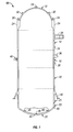
- Fig. 1 is a schematic illustration of a reactor pressure vessel (RPV) 10.
- RPV 10 includes a top head 12, four substantially cylindrical shell courses 14, 16, 18 and 20, and a bottom head assembly 22.
- Top head 12 includes a head flange 24.
- First shell course 14 includes a vessel flange (not shown).
- Top head 12 is bolted to first shell course 14 by bolts 26 which extend through head flange 24.
- Top head 12 also includes a head spray and vent nozzle 28 and lifting flanges 30 used when lifting top head 12 from first shell course 14.
- First shell course 14 includes main steam nozzles 32 through which steam flows out of the RPV 10. Stabilizer brackets 34 also are formed on first shell course 14. Second shell course 16 has a number of nozzles 36, 38 and 40 formed therein. Fourth shell course 20 includes a support skirt 42 welded thereto. Support skirt 42 is utilized to support RPV 10 within the reactor housing (not shown).
- Bottom head assembly 22 includes a bottom head dome 44 having a plurality of stub tubes 46 welded thereto.
- Stub tubes 46 are substantially cylindrical and each stub tube 46 has a bore (not shown in Fig. 1) extending therethrough. The bore of each stub tube 46 is aligned with an opening (not shown in Fig. 1) in bottom head dome 44.
- Components such as control rod drives, in-core instruments, pressure instrument nozzles, and drain nozzles extend through such bottom head dome openings and stub tube bores and penetrate into RPV 10.
- Fig. 1 is provided primarily for illustrative purposes to show a typical bottom head assembly 22.
- the present invention as described below, can be used in many RPV configurations other than RPV 10.
- Fig. 2 is a partial cross-section view of a control rod drive housing 50, one stub tube 46, and bottom head dome 44 of RPV 10 wherein control rod drive housing 50 is sealed to stub tube 46 in accordance with one embodiment of the present invention.
- bottom head dome 44 has a thickness T BH , and includes a substantially cylindrical opening 52 therein defined by a sidewall 54.
- Stub tube 46 includes a first end 56 and a second end 58, and a stub tube bore 60 extends between first and second ends 56 and 58.
- Stub tube 46 is positioned concentric bottom head dome opening 52 so that stub tube bore 60 is substantially aligned with bottom head dome opening 52.
- Stub tube 46 is secured to bottom head dome 44 with a lower stub attachment weld 62.
- an outer surface 64 of stub tube sidewall 66 proximate second end 58 is welded to bottom head dome 44 with lower stub tube attachment weld 62.
- Control rod drive housing 50 includes a first end (not shown) a second end (not shown) and a bore 68 extending between the first and second ends.
- control rod drive housing 50 has a substantially hollow cylindrical geometric shape including a sidewall 70 having an outer surface 72 and an inner surface 74 which defines bore 68.
- Control rod drive housing 50 is positioned so that it extends through bottom head dome opening 52 and stub tube bore 60.
- An upper portion 76 of control rod drive housing 50 is secured to stub tube 46 with an upper stub tube attachment weld 78 adjacent stub tube first end 56 so that control rod drive housing 50 is substantially concentrically and fixedly secured within stub tube 46.
- control rod drive housing 50 within stub tube 46 and bottom head dome 44 is well known. Furthermore, bottom head 44 is fabricated from low alloy steel, and stub tube 46 and control rod housing 50 are fabricated from a compatible corrosion resistant materials such as stainless steel or Ni--Cr--Fe.
- CRD housing 50 is cut at a location 86 below upper stub tube attachment weld 78.
- control rod drive housing 50 is cut at location 86 below stub tube second end 58 to separate upper portion 76 of control rod drive housing 50 from a lower portion 92 of control rod drive housing 50.
- the lower portion 92 is not removed, but remains in place.
- bottom head dome opening 52 is cleaned.
- a grinder (not shown) may be extended into bottom head dome opening 52 and utilized to grind sidewall 54 of bottom head dome opening 52 between a lower end 88 of upper portion 76 and a bottom end 90 of bottom head dome 44 to form a weld passage (e.g., area over which a weld may be applied) between lower end 88 and bottom end 90.
- bottom head dome opening 52 may be cleaned with a flapper wheel or by honing. Methods for cleaning bottom head dome opening 52 are known.
- Existing lower portion 92 is then re-attached so that it is substantially aligned with and adjacent to upper portion 76.
- Existing lower portion 92 is a substantially hollow member having a substantially cylindrical geometric shape. More particularly, existing lower portion 92 includes an upper end 94, a lower end (not shown), and a bore 96 extending between upper end 94 and the lower end.
- Upper end 94 of existing lower portion 92 includes a weld prep 98 for welding upper end 94 to sidewall 54 of bottom head dome opening 52.
- upper end 94 of existing lower portion 92 is cleaned in accordance with known methods so that upper end 94 has a substantially frusto-conical geometric shape. This provides a clean oxide-free surface to form weld prep 98.
- a grinder may be used to grind upper end 94.
- upper end 94 may be cleaned with a flapper wheel or by honing.
- Existing lower portion 92 is re-attached in bottom head dome opening 52 so that upper end 94 is proximate lower end 88 of remaining upper portion 76 and so that control rod housing bore 68 remains substantially aligned with bore 96. As shown in Fig. 2, upper end 94 of existing lower portion 92 is spaced from lower end 88 of remaining upper portion 76.
- the lower portion 92 within bottom head dome opening 52 is re-attached to sidewall 54 of bottom head dome opening 52 without also being secured to lower end 88 of remaining portion 76.
- the existing lower portion 92 is preferably re-attached at a point different then the location where it was initially cut, e.g., lower than where lower portion 92 was cut initially at location 86 below stub tube second end 58 to separate upper portion 76 of control rod drive housing 50 from lower portion 92.
- upper end 94 of lower portion 92 is bead welded to provide a weld 97, using known welding methods such as temper bead welding techniques, to sidewall 54 of bottom head dome opening 52.
- the weld 97 is provided at a location that is preferably at a point below potential differential leakage paths in the CRD 50.
- this location may be at a point that is lower than annulus leakage path 80 between inner surface 82 of stub tube sidewall 66 and outer surface 72 of CRD 50; and/or below annulus leakage path 84 formed between outer surface 72 of control rod drive housing 50 and sidewall 54 of bottom head dome opening 52, as shown in Fig. 2.
- an automatic welding machine may be inserted through bore 96 so that a welding head is substantially adjacent to weld prep 98.
- the automatic welding machine then may be used to apply a temper bead weld 97 to sidewall 54 of bottom head dome opening 52, as is known.
- a UT machine for example, may then be inserted through bore 96 to ascertain the quality of the bead weld.
- the CRD housing 50 is sealed at the top, near upper section 76 to provide a dry environment inside.
- the outside of the CRD housing 50 remains wet.
- an apparatus or tool such as a weld head is inserted from a bottom end (not shown) of the CRD housing 50.
- the weld head may be as much as 13 feet in length or longer.
- the weld head may include a gas-tungsten arc welding head near the top of the weld head.
- the gas-tungsten arc welding head may include a torch and a weld wire feeder, and rotates and moves up or down, in a slow manner in order to apply a thin cladding layer.
- the cladding 89 is corrosion resistant due to its fine ferrite structure.
- the cladding material typically consists of a metal alloy, such as Alloy 82, Type 308L stainless steel or Type 316L stainless steel; however, the cladding of the present invention is not limited to these alloys.
- cladding 89 may be alloyed with a noble metal to provide additional mitigation to stress corrosion cracking.
- a welding apparatus and technique used to apply the cladding with alloyed noble metal is described in commonly assigned U.S. Patent Application Serial No. 09/416,943 to OFFER et al., entitled APPARATUS AND METHOD FOR CORROSION RESISTANT CLADDING. Briefly described, the welding technique joins the cladding 89 to the heat affected zone 99, which is a region susceptible to stress corrosion cracking.
- the cladding 89 may be applied under conditions of low heat input to achieve reduced or no thermal sensitization at the edges of the newly clad region.
- the apparatus applies a cladding that includes a filler material comprised of nickel-base alloys or iron-base stainless steels such as the aforementioned Inconel 82, Stainless 308L or Stainless 316L, which may be alloyed with a low concentration of a noble metal element (e.g., palladium, platinum, rhodium, or combinations thereof) to act as a catalyst for improved recombination rates of oxygen with hydrogen, at reduced hydrogen addition levels.
- the concentration of noble metal in the filler material may preferably be in the region of about 1% by weight or less, more usually about 0.25 to 0.75% by weight after dilution by base metal. Recombination of the oxygen and hydrogen peroxide with hydrogen reduces the effective electrochemical potential, in order to reduce the susceptibility to IGSCC.
- the apparatus remotely applies the cladding 89, at a significant distance from the end of the apparatus as noted above.
- the apparatus has the ability to provide a very stable arc voltage (and corresponding arc length control) even though the torch is positioned far from weld head drive mechanisms.
- the apparatus may include a rotating wire feeder which produces a wire pool very far downstream of the distal end of the wire feeder. Weldability at very low, yet stable, wire feed rates (e.g., approximately 60-80 cm/min) is therefore improved, enabling very thin cladding to be reliably deposited, with a cladding thickness preferably in a range of about 0.3-0.6 mm, and more preferably between about 0.36 to 0.45 mm thick.
- the welding torch of the apparatus uses sufficiently low heat input (in a range of about 0.6-1.0 kJ/cm, for example) that a required through-wall temperature gradient for far-wall stress improvement can be obtained, even without liquid cooling on a far wall.
- the reduced heat input to apply the cladding 89 may be produced in part by a travel speed (torch speed) in excess of about 10 inches per minute, for example 15 to 40 inches per minute, more usually 15-30 inches per minute, so that the time in the sensitizing temperature range during cooling of the applied cladding 89 is insufficient to allow carbides to precipitate on the grain boundaries.
- travel speed in excess of about 10 inches per minute, for example 15 to 40 inches per minute, more usually 15-30 inches per minute
- Sensitization control may be effected utilizing dual controls on welding parameters: (1) heat input (controlled as a function of the heat input per unit length of bead), and (2) heat affected zone cooling rate (controlled as a function of the welding linear speed in the forward direction).
- heat input controlled as a function of the heat input per unit length of bead
- heat affected zone cooling rate controlled as a function of the welding linear speed in the forward direction.
- cross-bead arc oscillation is avoided, since it is counterproductive with respect to maintaining both the required low heat input and high travel speed.
- electric-arc based cladding processes may be applied to the heat affected zone 99 even with very low resistance to thermal sensitization, and without high risk of sensitization.
- the method of permanently repairing or sealing a CRD housing/stub tube can also be applied to in-core monitor housings (ICMH).
- An ICMH is smaller diameter vessel penetration than the CRD housing/stub tube located in a reactor pressure vessel bottom head region. There are typically between about 29-70 ICMH's, depending upon the size of the reactor pressure vessel.
- the method may be applied to ICMHs that do not contain a stub tube, but include a weld buildup that approximates the functions and structure of a stub tube.
- the method and apparatus described above for applying the cladding may also be used to apply cladding on ICMH's. Further, the method and apparatus for applying the cladding may be used to apply the weld 97 shown in Fig. 2. In other words, weld 97 may be a metal that is alloyed with a noble metal to reduce susceptibility to IGSCC.
- the above-described method facilitates permanent repairing stress corrosion cracks adjacent the upper stub tube weld and the lower stub tube weld, more quickly and more easily than known methods.
- such repairs may be substantially completed from below the bottom head dome, and may significantly reduce stresses typically caused by thermal growth mismatches between the CRD housing and the bottom head dome.
- the re-attachment weld does not affect the existing stub tube and the upper housing section, so there are no additional stresses induced from the process of re-attaching the existing lower portion 92 to the CRD 50.
- the method permanently mitigates the potential damage due to leaking CRD stub tubes, regardless of origin, without adversely affecting the remaining stub tube/CRD housing. Additionally, since the existing lower portion 92 of CRD housing 50 is re-used and remains in place, there are minimal alignment issues, and existing CRD hydraulic lines are unaffected. Moreover, overall implementation time is shorter than current permanent repair options, reducing critical path outage time and reducing the dose received by maintenance personnel during the repair.
- the cladding techniques may be applied to a re-attachment weld in repairs where a lower portion member such as a replacement lower portion of a CRD housing is inserted in place of a defective lower portion and welded to an upper portion of a CRD housing and/or a sidewall of a bottom head dome opening in a reactor pressure vessel.
Landscapes
- Physics & Mathematics (AREA)
- Engineering & Computer Science (AREA)
- Plasma & Fusion (AREA)
- General Engineering & Computer Science (AREA)
- High Energy & Nuclear Physics (AREA)
- Butt Welding And Welding Of Specific Article (AREA)
- Pressure Welding/Diffusion-Bonding (AREA)
Applications Claiming Priority (2)
| Application Number | Priority Date | Filing Date | Title |
|---|---|---|---|
| US10/193,992 US6834092B2 (en) | 2002-07-15 | 2002-07-15 | Method of repairing leaking elongate hollow members in boiling water reactors |
| US193992 | 2002-07-15 |
Publications (3)
| Publication Number | Publication Date |
|---|---|
| EP1383136A2 true EP1383136A2 (de) | 2004-01-21 |
| EP1383136A3 EP1383136A3 (de) | 2010-01-06 |
| EP1383136B1 EP1383136B1 (de) | 2012-09-12 |
Family
ID=29780151
Family Applications (1)
| Application Number | Title | Priority Date | Filing Date |
|---|---|---|---|
| EP03254375A Expired - Lifetime EP1383136B1 (de) | 2002-07-15 | 2003-07-10 | Reparaturverfahren für undichte, langgestreckte, hohle Bauteile in einem Siedewasserreaktor |
Country Status (4)
| Country | Link |
|---|---|
| US (1) | US6834092B2 (de) |
| EP (1) | EP1383136B1 (de) |
| JP (1) | JP4494737B2 (de) |
| ES (1) | ES2394201T3 (de) |
Cited By (1)
| Publication number | Priority date | Publication date | Assignee | Title |
|---|---|---|---|---|
| EP1596400A3 (de) * | 2004-05-14 | 2010-02-17 | General Electric Company | Reparaturverfahren eines undichten hohlen Bauteils in einem Siedewasserreaktor |
Families Citing this family (8)
| Publication number | Priority date | Publication date | Assignee | Title |
|---|---|---|---|---|
| US7374823B2 (en) * | 2003-02-28 | 2008-05-20 | Press Kogyo Co., Ltd. | Welded portion constitution and welding method |
| FR2866148B1 (fr) * | 2004-02-06 | 2006-07-21 | Framatome Anp | Procede de fixation d'un tube dans un alesage traversant une paroi spherique et dispositif de depot metal d'apport dans un lamage. |
| US9281085B2 (en) * | 2005-03-29 | 2016-03-08 | Azz Wsi Llc | Method of providing and evaluating a mid-wall repair |
| FR2902569B1 (fr) * | 2006-06-16 | 2008-09-12 | Areva Np Sas | Procede de reparation d'une penetration de fond de cuve d'un reacteur nucleaire |
| JP5687481B2 (ja) * | 2010-12-10 | 2015-03-18 | 株式会社東芝 | ジェットポンプ計測用配管の補修方法 |
| JP5794944B2 (ja) * | 2012-03-29 | 2015-10-14 | 三菱重工業株式会社 | 拡管方法 |
| FR2990554B1 (fr) * | 2012-05-09 | 2016-01-01 | Areva Np | Procede de reparation d'un equipement chaudronne de reacteur nucleaire |
| EP3355022B1 (de) * | 2017-01-31 | 2019-10-30 | Alfa Laval Corporate AB | Vorrichtung und verfahren zum schutz des rohrbodens eines syngas-kreiskessels |
Family Cites Families (16)
| Publication number | Priority date | Publication date | Assignee | Title |
|---|---|---|---|---|
| US3723742A (en) * | 1968-04-11 | 1973-03-27 | Trw Inc | Radioisotope capsule protection structure |
| JPS578490A (en) * | 1980-06-19 | 1982-01-16 | Hitachi Ltd | Method of repairing control rod drive housing |
| US4432824A (en) * | 1980-07-31 | 1984-02-21 | Raychem Corporation | Method for internal pipe protection |
| US4510171A (en) * | 1981-09-11 | 1985-04-09 | Monsanto Company | Clad metal joint closure |
| US4444555A (en) * | 1982-04-26 | 1984-04-24 | Koppers Company, Inc. | Method for reducing stress corrosion cracking in high-temperature regenerative air heaters |
| US4480841A (en) | 1982-10-13 | 1984-11-06 | Combustion Engineering, Inc. | Apparatus and method for sealing a tube joint |
| US4611813A (en) * | 1984-09-28 | 1986-09-16 | Combustion Engineering Co., Inc. | Method of and apparatus for providing an annular seal |
| US4647749A (en) * | 1985-01-17 | 1987-03-03 | Joy Manufacturing Company | Apparatus and method for weld cladding cylindrical objects |
| US4826217A (en) * | 1986-03-31 | 1989-05-02 | Combustion Engineering, Inc. | Apparatus and method for sealing a tube joint |
| SE457029B (sv) * | 1987-03-30 | 1988-11-21 | Asea Atom Ab | Taetningsanordning vid kaernkraftreaktor |
| SE466370B (sv) * | 1990-06-27 | 1992-02-03 | Asea Atom Ab | Metod foer taetning av laeckage fraan en drivdonsstuts i en kaernkraftreaktor |
| US5274683A (en) * | 1993-04-27 | 1993-12-28 | B&W Nuclear Service Company | Method for replacing a nozzle |
| FR2714763B1 (fr) * | 1993-12-30 | 1996-03-15 | Framatome Sa | Procédé et dispositif de réalisation d'un revêtement protecteur étanche sur une surface d'un composant de réacteur nucléaire et applications. |
| US5796797A (en) | 1997-02-14 | 1998-08-18 | General Electric Company | Method for sealing a stub tube in a nuclear reactor |
| JP2981184B2 (ja) * | 1997-02-21 | 1999-11-22 | トーカロ株式会社 | ボイラ伝熱管および管内面デポジット付着抑制効果に優れるボイラ伝熱管の製造方法 |
| US5809098A (en) | 1997-03-10 | 1998-09-15 | General Electric Company | Method for sealing a stub tube in a nuclear reactor |
-
2002
- 2002-07-15 US US10/193,992 patent/US6834092B2/en not_active Expired - Fee Related
-
2003
- 2003-07-10 EP EP03254375A patent/EP1383136B1/de not_active Expired - Lifetime
- 2003-07-10 ES ES03254375T patent/ES2394201T3/es not_active Expired - Lifetime
- 2003-07-15 JP JP2003274398A patent/JP4494737B2/ja not_active Expired - Lifetime
Non-Patent Citations (1)
| Title |
|---|
| None |
Cited By (1)
| Publication number | Priority date | Publication date | Assignee | Title |
|---|---|---|---|---|
| EP1596400A3 (de) * | 2004-05-14 | 2010-02-17 | General Electric Company | Reparaturverfahren eines undichten hohlen Bauteils in einem Siedewasserreaktor |
Also Published As
| Publication number | Publication date |
|---|---|
| EP1383136A3 (de) | 2010-01-06 |
| US20040008807A1 (en) | 2004-01-15 |
| US6834092B2 (en) | 2004-12-21 |
| JP4494737B2 (ja) | 2010-06-30 |
| ES2394201T3 (es) | 2013-01-23 |
| EP1383136B1 (de) | 2012-09-12 |
| JP2004037465A (ja) | 2004-02-05 |
Similar Documents
| Publication | Publication Date | Title |
|---|---|---|
| JP2011075453A (ja) | 管台溶接方法、管台部補修方法および管台溶接構造 | |
| JPS6318714B2 (de) | ||
| US6834092B2 (en) | Method of repairing leaking elongate hollow members in boiling water reactors | |
| US7206372B2 (en) | Methods of repairing leaking elongate hollow members in boiling water reactors | |
| US9180557B1 (en) | Two-piece replacement nozzle | |
| US6888908B1 (en) | Reactor head with integral nozzles | |
| US5796797A (en) | Method for sealing a stub tube in a nuclear reactor | |
| US5809098A (en) | Method for sealing a stub tube in a nuclear reactor | |
| JP2001091688A (ja) | 原子力発電プラント | |
| JP2007232457A (ja) | 貫通管台補修方法及び管台孔栓 | |
| JP3127512B2 (ja) | 炉内構造物の保全方法 | |
| JP3660770B2 (ja) | 炉内構造物の交換方法 | |
| JP3679823B2 (ja) | 炉心シュラウドの交換方法 | |
| JPH0886896A (ja) | 原子炉内シュラウドならびにその据付方法および交換方法 | |
| US9978467B2 (en) | Excavation and weld repair methodology for pressurized water reactor piping and vessel nozzles | |
| KR20060051542A (ko) | 금속 접합 방법 | |
| US20030121956A1 (en) | Apparatus and method for corrosion resistant cladding | |
| JPH10153682A (ja) | 炉心シュラウドの交換方法 | |
| Tamura et al. | Development of underwater laser cladding and underwater laser seal welding techniques for reactor components (II) | |
| KR102503724B1 (ko) | 노즐 전체교체방법 | |
| JPS6362717B2 (de) | ||
| JP3471295B2 (ja) | 炉心スプレイスパージャの取替方法 | |
| US20130294566A1 (en) | Control rod drive (crd) tubes, method of manufacture, and installation thereof | |
| JP2000230996A (ja) | 原子炉構造物の補修方法 | |
| Matsumoto | Core shroud replacement of Fukushima-Daiichi Unit# 3 |
Legal Events
| Date | Code | Title | Description |
|---|---|---|---|
| PUAI | Public reference made under article 153(3) epc to a published international application that has entered the european phase |
Free format text: ORIGINAL CODE: 0009012 |
|
| AK | Designated contracting states |
Kind code of ref document: A2 Designated state(s): AT BE BG CH CY CZ DE DK EE ES FI FR GB GR HU IE IT LI LU MC NL PT RO SE SI SK TR |
|
| AX | Request for extension of the european patent |
Extension state: AL LT LV MK |
|
| PUAL | Search report despatched |
Free format text: ORIGINAL CODE: 0009013 |
|
| AK | Designated contracting states |
Kind code of ref document: A3 Designated state(s): AT BE BG CH CY CZ DE DK EE ES FI FR GB GR HU IE IT LI LU MC NL PT RO SE SI SK TR |
|
| AX | Request for extension of the european patent |
Extension state: AL LT LV MK |
|
| 17P | Request for examination filed |
Effective date: 20100706 |
|
| 17Q | First examination report despatched |
Effective date: 20100728 |
|
| AKX | Designation fees paid |
Designated state(s): CH DE ES FI LI SE |
|
| GRAP | Despatch of communication of intention to grant a patent |
Free format text: ORIGINAL CODE: EPIDOSNIGR1 |
|
| RIC1 | Information provided on ipc code assigned before grant |
Ipc: G21C 17/017 20060101ALI20120113BHEP Ipc: G21C 13/036 20060101AFI20120113BHEP |
|
| GRAS | Grant fee paid |
Free format text: ORIGINAL CODE: EPIDOSNIGR3 |
|
| GRAA | (expected) grant |
Free format text: ORIGINAL CODE: 0009210 |
|
| AK | Designated contracting states |
Kind code of ref document: B1 Designated state(s): CH DE ES FI LI SE |
|
| REG | Reference to a national code |
Ref country code: DE Ref legal event code: R081 Ref document number: 60342074 Country of ref document: DE Owner name: GENERAL ELECTRIC COMPANY, SCHENECTADY, US Free format text: FORMER OWNER: GENERAL ELECTRIC CO., SCHENECTADY, N.Y., US |
|
| REG | Reference to a national code |
Ref country code: CH Ref legal event code: EP |
|
| REG | Reference to a national code |
Ref country code: DE Ref legal event code: R096 Ref document number: 60342074 Country of ref document: DE Effective date: 20121108 |
|
| REG | Reference to a national code |
Ref country code: CH Ref legal event code: NV Representative=s name: SERVOPATENT GMBH, CH |
|
| REG | Reference to a national code |
Ref country code: SE Ref legal event code: TRGR |
|
| REG | Reference to a national code |
Ref country code: ES Ref legal event code: FG2A Ref document number: 2394201 Country of ref document: ES Kind code of ref document: T3 Effective date: 20130123 |
|
| PLBE | No opposition filed within time limit |
Free format text: ORIGINAL CODE: 0009261 |
|
| STAA | Information on the status of an ep patent application or granted ep patent |
Free format text: STATUS: NO OPPOSITION FILED WITHIN TIME LIMIT |
|
| 26N | No opposition filed |
Effective date: 20130613 |
|
| REG | Reference to a national code |
Ref country code: DE Ref legal event code: R097 Ref document number: 60342074 Country of ref document: DE Effective date: 20130613 |
|
| REG | Reference to a national code |
Ref country code: CH Ref legal event code: PCAR Free format text: NEW ADDRESS: WANNERSTRASSE 9/1, 8045 ZUERICH (CH) |
|
| PGFP | Annual fee paid to national office [announced via postgrant information from national office to epo] |
Ref country code: SE Payment date: 20220622 Year of fee payment: 20 |
|
| PGFP | Annual fee paid to national office [announced via postgrant information from national office to epo] |
Ref country code: FI Payment date: 20220617 Year of fee payment: 20 |
|
| PGFP | Annual fee paid to national office [announced via postgrant information from national office to epo] |
Ref country code: ES Payment date: 20220801 Year of fee payment: 20 Ref country code: DE Payment date: 20220621 Year of fee payment: 20 |
|
| PGFP | Annual fee paid to national office [announced via postgrant information from national office to epo] |
Ref country code: CH Payment date: 20220802 Year of fee payment: 20 |
|
| REG | Reference to a national code |
Ref country code: DE Ref legal event code: R071 Ref document number: 60342074 Country of ref document: DE |
|
| REG | Reference to a national code |
Ref country code: CH Ref legal event code: PL |
|
| REG | Reference to a national code |
Ref country code: ES Ref legal event code: FD2A Effective date: 20230726 |
|
| REG | Reference to a national code |
Ref country code: SE Ref legal event code: EUG |
|
| PG25 | Lapsed in a contracting state [announced via postgrant information from national office to epo] |
Ref country code: ES Free format text: LAPSE BECAUSE OF EXPIRATION OF PROTECTION Effective date: 20230711 |