EP1382926A1 - Verdampfer für Kfz-Klimaanlagen - Google Patents
Verdampfer für Kfz-Klimaanlagen Download PDFInfo
- Publication number
- EP1382926A1 EP1382926A1 EP03015967A EP03015967A EP1382926A1 EP 1382926 A1 EP1382926 A1 EP 1382926A1 EP 03015967 A EP03015967 A EP 03015967A EP 03015967 A EP03015967 A EP 03015967A EP 1382926 A1 EP1382926 A1 EP 1382926A1
- Authority
- EP
- European Patent Office
- Prior art keywords
- evaporator
- collecting
- refrigerant
- air
- chamber
- Prior art date
- Legal status (The legal status is an assumption and is not a legal conclusion. Google has not performed a legal analysis and makes no representation as to the accuracy of the status listed.)
- Granted
Links
- 238000004378 air conditioning Methods 0.000 title claims description 4
- 239000003507 refrigerant Substances 0.000 claims description 44
- 238000005192 partition Methods 0.000 claims description 13
- 239000006200 vaporizer Substances 0.000 claims 3
- 239000002826 coolant Substances 0.000 abstract 3
- 238000010276 construction Methods 0.000 description 18
- 238000010586 diagram Methods 0.000 description 5
- 239000007788 liquid Substances 0.000 description 5
- 238000009434 installation Methods 0.000 description 4
- XLYOFNOQVPJJNP-UHFFFAOYSA-N water Substances O XLYOFNOQVPJJNP-UHFFFAOYSA-N 0.000 description 3
- 230000002349 favourable effect Effects 0.000 description 2
- 238000002347 injection Methods 0.000 description 2
- 239000007924 injection Substances 0.000 description 2
- 239000007921 spray Substances 0.000 description 2
- 230000003247 decreasing effect Effects 0.000 description 1
- 230000005484 gravity Effects 0.000 description 1
- 238000004519 manufacturing process Methods 0.000 description 1
- 239000007787 solid Substances 0.000 description 1
- 239000000243 solution Substances 0.000 description 1
- 238000011144 upstream manufacturing Methods 0.000 description 1
Images




Classifications
-
- F—MECHANICAL ENGINEERING; LIGHTING; HEATING; WEAPONS; BLASTING
- F28—HEAT EXCHANGE IN GENERAL
- F28D—HEAT-EXCHANGE APPARATUS, NOT PROVIDED FOR IN ANOTHER SUBCLASS, IN WHICH THE HEAT-EXCHANGE MEDIA DO NOT COME INTO DIRECT CONTACT
- F28D1/00—Heat-exchange apparatus having stationary conduit assemblies for one heat-exchange medium only, the media being in contact with different sides of the conduit wall, in which the other heat-exchange medium is a large body of fluid, e.g. domestic or motor car radiators
- F28D1/02—Heat-exchange apparatus having stationary conduit assemblies for one heat-exchange medium only, the media being in contact with different sides of the conduit wall, in which the other heat-exchange medium is a large body of fluid, e.g. domestic or motor car radiators with heat-exchange conduits immersed in the body of fluid
- F28D1/04—Heat-exchange apparatus having stationary conduit assemblies for one heat-exchange medium only, the media being in contact with different sides of the conduit wall, in which the other heat-exchange medium is a large body of fluid, e.g. domestic or motor car radiators with heat-exchange conduits immersed in the body of fluid with tubular conduits
- F28D1/053—Heat-exchange apparatus having stationary conduit assemblies for one heat-exchange medium only, the media being in contact with different sides of the conduit wall, in which the other heat-exchange medium is a large body of fluid, e.g. domestic or motor car radiators with heat-exchange conduits immersed in the body of fluid with tubular conduits the conduits being straight
- F28D1/0535—Heat-exchange apparatus having stationary conduit assemblies for one heat-exchange medium only, the media being in contact with different sides of the conduit wall, in which the other heat-exchange medium is a large body of fluid, e.g. domestic or motor car radiators with heat-exchange conduits immersed in the body of fluid with tubular conduits the conduits being straight the conduits having a non-circular cross-section
- F28D1/05366—Assemblies of conduits connected to common headers, e.g. core type radiators
- F28D1/05375—Assemblies of conduits connected to common headers, e.g. core type radiators with particular pattern of flow, e.g. change of flow direction
-
- F—MECHANICAL ENGINEERING; LIGHTING; HEATING; WEAPONS; BLASTING
- F28—HEAT EXCHANGE IN GENERAL
- F28F—DETAILS OF HEAT-EXCHANGE AND HEAT-TRANSFER APPARATUS, OF GENERAL APPLICATION
- F28F9/00—Casings; Header boxes; Auxiliary supports for elements; Auxiliary members within casings
- F28F9/02—Header boxes; End plates
- F28F9/0202—Header boxes having their inner space divided by partitions
- F28F9/0204—Header boxes having their inner space divided by partitions for elongated header box, e.g. with transversal and longitudinal partitions
- F28F9/0214—Header boxes having their inner space divided by partitions for elongated header box, e.g. with transversal and longitudinal partitions having only longitudinal partitions
Definitions
- the invention relates to a heat exchanger, in particular an evaporator for air conditioning systems of motor vehicles, in particular according to the preamble of claim 1.
- the today usual evaporators like disk evaporator and Flat tube evaporators are vertically in the air conditioner or the Vehicle installed, d. H. with vertical tubes.
- common Flat tube evaporator, z. B. known from DE-A 198 26 881 of Applicant are formed in two rows, d. H. with two rows of Flat tubes, which flows around one behind the other or in succession of air become.
- the ends of the manifolds open into collection boxes, each are divided into two chambers that receive the ends of the flat tubes.
- the refrigerant is once in depth with double-flow, d. H. deflected against the direction of air flow.
- Such flat tube evaporator have a height H, measured in the longitudinal direction of the tubes on and a width B, measured transversely to the tube longitudinal direction.
- the product out Height H and width B gives the face of the evaporator.
- the refrigerant can - in addition to the deflection in the depth - also deflected in the width become.
- This evaporator design is known to have a relationship from height to width of about 0.5 to 2.0, d. H. at the lowest Evaporators of this type, the height is about half the width.
- an evaporator of the above to create the type mentioned above a lower height at the same permanent face and the same power, if possible at a favorable Temperature profile.
- the solution to this problem arises from the characteristics of The invention provides a horizontal evaporator, in which the flow channels in installation position approximately horizontally and the lateral collecting chambers are arranged approximately vertically or flowed through.
- Vertical does not mean strictly vertical, since the evaporators are in Air conditioners can also be arranged slightly inclined. Such Arrangement should also be encompassed by the term about vertically.
- Through this Construction can have a ratio of height to width in the range of 1: 3 to 1: 6 or a ratio of width to height in the range of about 3 to 6 and more, that is advantageous to 7, 8, 9m or 10 or more realized without the performance of the evaporator decreasing. Opposite the Construction with vertical flow channels even results Performance gain. Furthermore, results with respect to the known construction vertical flow channels the advantage of a smaller number of parts, since the inventive evaporator longer, but fewer tubes or Has flow channels. This reduces the manufacturing costs.
- the evaporator as Disk or flat tube evaporator formed, wherein the Flat tube evaporator proves to be particularly advantageous. He can in principle with almost the same or similar components as mentioned above The state of the art of the applicant to be built - but in a lying Construction with correspondingly low height and large width.
- Arrangement of partitions in the collecting tanks can be a two- or multiple flooding with deflection of the refrigerant in the depth and the Height allows for a favorable temperature distribution for the out the air exiting the evaporator causes.
- the injection takes place of the refrigerant in the pipes below or in the bottom the collection chamber.
- the refrigerant is then in the upper Suction area in the vaporous or superheated state. That's it possible, the evaporator according to the invention also with a operate conventional expansion valve.
- the input and Outlet openings are both arranged at the bottom of a collection box, Then there are the overflow for the deflection of the refrigerant in the depth in the upper part of the vertical partition. This will prevents liquid refrigerant from being sucked out.
- the input and Outlet openings are both arranged at the top of a collection box, Then there are the overflow for the deflection of the refrigerant in the depth in the lower part of the vertical partition. This will ensures that only vaporous refrigerant is sucked off.
- the evaporator has side parts on, wherein the lower side part recesses for the Has condensate drain. Since the flat tubes are horizontal, that will be in moist air condensate formed by the air flow. Between the flat tube rows, it can - following the gravity - after Drain down and drain through the recesses. This will be unpleasant evaporator odor avoided. In addition, at the air outlet side end area of the evaporator Splash water grille for Be intercepted catching the sprayed condensate.
- At least one or more recesses are provided, such as for example, a plurality of elongated recesses. It can be useful if the recesses in the side part substantially the downstream or on the outflow side are arranged. With another Embodiment, it may also be appropriate if the Recess / the recesses are on the inflow side or over both areas at least partially, ie outflow or arrival or Inflow side, lie.
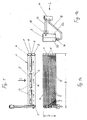
- Fig. 1, 1a and 1b show a double-row, double-flow Flat tube evaporator 1 in horizontal mounting position, that is with lying Flat tubes, in a view from below.
- the air flow direction is through the arrow L marked.
- Fig. 1a shows the evaporator 1 with a view of its end face, through the Height H and the width B is defined.
- the front side of the evaporator 1 shows a total of ten flat tubes 2, between which corrugated fins 3 are arranged are.
- the flat tubes 2 open on both sides in headers 4, 5, the are each divided by a longitudinal partition 6 in two chambers 7, 8 (The division of the chamber 5 is not visible in Fig. 1 and 1a).
- the first flat tube row 9 opens into the chamber 7 and the opposite (hidden), while the second flat tube row 10 (hidden), shown by arrows 10, into the chamber 8 and the opposite chamber (hidden) opens.
- the evaporator 1 has two Refrigerant connections, namely a refrigerant inlet 14 and a Refrigerant outlet 15, which via a refrigerant supply line 16 and a Refrigerant discharge 17 are connected to an expansion valve 18 (Fig. 1b).
- the injection of the refrigerant is thus at the bottom of the Evaporator 1, and first in the air flow direction (arrow L) flows behind pipe row 10 of refrigerant.
- the refrigerant then passes into the rear chamber 8 of the collecting tank 4.
- In the Partition 6 are arranged through openings 19 through which the Refrigerant in the direction of air flow in the front chamber 7 passes (Deflection in depth). From there it enters the front row of flat tubes 9 and then into the collecting box 5, its rear chamber 5a and front Chamber 5b in Fig. 1b can be seen.
- the refrigerant is in the upper Area of the chamber 5b sucked through the connection piece 15.
- the flat tube evaporator 1 is - as already mentioned - lying, so as in illustrated in the drawing, installed in the air conditioning of the motor vehicle and by the air to be cooled in the direction of the arrow L flows. In this respect results for the flow between refrigerant and air Cross counter flow.
- the flat tube evaporator has in the illustrated Embodiment, a width B of 500 mm, this width the includes two headers 4, 5 with.
- the height H of the evaporator is 120 mm. This results in a ratio of width B to height H from 4,16.
- FIG. 1 c shows an evaporator in a view from below, in which for the same components, the same reference numerals are used as in FIG. 1a.
- the openings 13 'for condensate drain on the other side in Compared to the embodiment of Figure 1a are arranged.
- the drain 13 for the condensate on the Air upstream side arranged in the side part is the drain 13 for the condensate on the Air upstream side arranged in the side part, whereas in the Embodiment of Figure 1c, the outlet 13 'on the downstream side or Outflow side is arranged in the side part.
- the drain for a condensate which condenses on the surface of the evaporator, also on both the On as well as on the downstream side of the side part.
- the recesses are formed by elongated cutouts, they but also as round cutouts or other cutouts be educated.
- Fig. 2 shows a modified embodiment of a Flat tube evaporator 20 in a schematic representation, d. H. Pipes and Ribs are not shown, but essentially by Flow arrows replaced.
- the flat tube evaporator 20 has - similar to in Embodiment of FIG. 1 - a lying flat tube bundle 21, which is a front tube bundle half 21a and a rear one Tube bundle half 21b has.
- the air containing the flat tube evaporator 20 in Flows through the direction of arrows L, but first hits the rear Flat tube bundle half 21b.
- Both sides of the flat tube bundle 21 are Collecting boxes 22, 23 arranged, in which the not shown Flat tubes of bundle 21 open.
- the one on the left in the drawing Collection box 22 is by a continuous, vertically arranged Partition wall 24 in a front chamber 22 a and in a rear chamber 22 b divided, wherein the front chamber 22 a an inlet opening 25 and the rear chamber 22b has an outlet opening 26 for the refrigerant. Inlet and outlet openings 25, 26 are thus both on the lower side of the Flat tube evaporator 20, capable of, as shown in the drawing is shown installed in the vehicle.
- the one in the drawing on the right located collecting box 23 has a vertically arranged partition 27 on which the collecting box 23 in a front chamber 23 a and in a divided rear chamber 23b.
- the partition 27 has in its upper Region, preferably in its upper half three overflow openings 28th on which the two adjacent chambers 23a, 23b with each other connects (fewer or more openings are also possible).
- the flat tube evaporator 20 is traversed by double-flow of refrigerant, and although in the following way: the refrigerant passes in the direction of arrow E. the opening 25 in the front chamber 22 a and then flows through the leading tube bundles 21a, following the arrows V, in the chamber 23a on the right side of the evaporator 20.
- the refrigerant is in a liquid state enters the chamber 23a and partially becomes en route to the chamber 23a evaporates, d. H. a part of the refrigerant flowing into the chamber 23a is still liquid. Therefore, the overflow openings 28 are in the upper region arranged the partition 27, so that an overflow of liquid Refrigerant from the front chamber 23 a in the rear chamber 23 b is prevented.
- overflow 28 thus occurs predominantly Refrigerant in the vapor state in the chamber 23b over - here ie in the direction of the arrow U the deflection of the refrigerant "in the depth", d. H. against the air flow direction L.
- Refrigerant then into the rear tube bundle 21b and flows through this in the direction of arrow R until it enters the exit chamber 22b. From there The refrigerant enters the vapor state through the outlet opening 26th in the lower region of the chamber 22b from the flat tube evaporator 20.
- FIG. 2 Another, not shown embodiment of the Flat tube evaporator is possible, with overhead inlet E and outlet A (corresponding to Fig. 2).
- the evaporator 20 according to FIG. 2 would be to rotate about its longitudinal axis by 180 °, so that the inlet opening 25th and the outlet opening 26 are at the top and the overflow openings 28 in the lower half of the partition 27 would come to rest.
- the liquid refrigerant would then remain essentially at the bottom of the evaporator, so that only vaporous refrigerant would be sucked off.
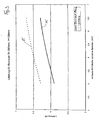
- Fig. 3 shows a performance comparison between conventional Evaporator design with vertical pipes and inventive Construction with horizontal pipes.
- the end face thus corresponds to the Product B x H.
- the solid curve K which lies well below the curve E, refers to Evaporator in conventional construction, d. H. with vertical Pipes, horizontal collecting tanks within one Ratio of B to H from 2.9 to 5.4.
- the underperformance compared to the Construction according to the invention results from a variety of Refrigerant deflections and the resulting refrigerant side Pressure drop.
- Fig. 4 shows another diagram in which the specific usable space, i. H. the ratio of usable space to installation space is plotted over the free one End face (this is the product B 'x H, where B' the order the height of the collection boxes is reduced width).
- the top dashed Curve E corresponds to the construction according to the invention, while the underneath lying horizontally extending curve K of conventional construction with vertical tubes corresponds. It is obvious that the Construction according to the invention with lying pipes a relatively larger free End face offers, because the portion of the collecting boxes at the entire Face is much lower than that of the conventional construction at such a width-to-height ratio is the case.
- Fig. 5 shows another diagram in which the air-side pressure drop at Evaporator is applied over the total end face including the Area of the collectors.
- the dashed line E again denotes the according to the invention and the solid line K the conventional Construction.
- the pressure drop for the invention is therefore much cheaper out. This advantage in favor of the invention is again due to the lower proportions of the collection boxes at the total end face in the Invention.
Landscapes
- Engineering & Computer Science (AREA)
- Physics & Mathematics (AREA)
- Thermal Sciences (AREA)
- Mechanical Engineering (AREA)
- General Engineering & Computer Science (AREA)
- Heat-Exchange Devices With Radiators And Conduit Assemblies (AREA)
- Air-Conditioning For Vehicles (AREA)
Abstract
Description
- Fig. 1
- einen liegenden Verdampfer in zweiflutiger Durchströmung in Flachrohrbauweise in einer Ansicht von unten,
- Fig. 1a
- den Verdampfer gemäß Fig. 1 in einer Ansicht von vorne,
- Fig. 1b
- den Verdampfer gemäß Fig. 1 in einer Seitenansicht,
- Fig. 1c
- ein Ausführungsbeispiel eines Verdampfers in einer Ansicht von unten,
- Fig. 2
- ein zweites Ausführungsbeispiel eines liegenden Verdampfers mit zweifacher Durchflutung in schematischer Darstellung,
- Fig. 3
- ein Diagramm zum Leistungsvergleich der erfindungsgemäßen und der herkömmlichen Bauweise,
- Fig. 4
- ein Diagramm zum Vergleich der erfindungsgemäßen und der herkömmlichen Bauweise im Hinblick auf den spezifischen Nutzraum und
- Fig. 5
- eine Diagramm zum Vergleich der erfindungsgemäßen und der herkömmlichen Bauweise im Hinblick auf den luftseitigen Druckabfall.
Claims (13)
- Verdampfer für Klimaanlagen von Kraftfahrzeugen, bestehend aus parallel verlaufenden, ein Kältemittel führenden Strömungskanälen, aus von Luft beaufschlagten zwischen den Strömungskanälen angeordneten Rippen sowie aus mindestens einer Sammelkammer mit Kältemitteleintritts- und/oder -austrittsöffnungen, wobei der Verdampfer einen Block mit einer in der Senkrechten gemessenen Höhe H und einer in der Horizontalen gemessenen Breite B aufweist, deren Produkt H x B die Stirnfläche des Verdampfers ergibt, dadurch gekennzeichnet, dass die Strömungskanäle in Einbaulage liegend, d. h. im Wesentlichen Horizontal und die Sammelkammer/n in senkrechter Richtung durchströmbar angeordnet sind und dass das Verhältnis V von Breite B zu Höhe H folgenden Bereich aufweist:
- Verdampfer nach Anspruch 1, dadurch gekennzeichnet, dass die Strömungskanäle und die Sammelkammern in Scheiben integriert sind und einen Scheibenverdampfer bilden.
- Verdampfer nach Anspruch 1, dadurch gekennzeichnet, dass die Strömungskanäle als Flachrohre (2) und die Sammelkammern als Sammelkästen (4, 5; 22, 23), in welche die Flachrohre (2) münden, ausgebildet sind.
- Verdampfer nach Anspruch 3, gekennzeichnet durch zwei Reihen (9, 10) von Flachrohren (2) und beiderseits der Flachrohrenden angeordnete Sammelkästen (4, 5), die jeweils in zwei Kammern (7, 8; 5a, 5b) für jede Flachrohrreihe (9, 10) unterteilt sind.
- Verdampfer nach Anspruch 4, dadurch gekennzeichnet, dass die Kältemitteleintrittsöffnung (14) im unteren Bereich einer Kammer (5a) eines Sammelkastens (5) angeordnet ist.
- Verdampfer nach Anspruch 4 oder 5, dadurch gekennzeichnet, dass die Kältemittelautrittsöffnung (15) im oberen Bereich einer Kammer (5b) eines Sammelkastens (5) angeordnet ist.
- Verdampfer nach Anspruch 5 oder 6, dadurch gekennzeichnet, dass Kältemittelein- und -austrittsöffnungen (14, 15) an dem selben Sammelkasten (5) angeordnet sind.
- Verdampfer nach einem der Ansprüche 4 bis 7, gekennzeichnet durch eine zweifache Durchflutung (V, R) mit einer Umlenkung U des Kältemittels in der Tiefe, d. h. entgegen der Luftströmungsrichtung L.
- Verdampfer nach Anspruch 7 oder 8, dadurch gekennzeichnet, dass Kältemitteleintritts- und austrittsöffnungen (25, 26) im unteren Bereich eines Sammelkastens (22) angeordnet sind und dass der andere Sammelkasten (23) eine senkrechte Trennwand (27) mit Überströmöffnungen (28) aufweist, die im oberen Bereich angeordnet sind.
- Verdampfer nach Anspruch 7 oder 8, dadurch gekennzeichnet, dass die Kältemitteleintritts- und austrittsöffnungen im oberen Bereich eines Sammelkastens angeordnet sind und dass der andere Sammelkasten eine senkrechte Trennwand mit Überströmöffnungen aufweist, die im unteren Bereich angeordnet sind.
- Verdampfer nach einem der vorhergehenden Ansprüche 3 bis 10, dadurch gekennzeichnet, dass beiderseits der Flachrohrreihen (9, 10) Seitenteile (11, 12) angeordnet sind, wobei das unten liegende Seitenteil (12) Aussparungen (13) für den Ablauf von Kondensat aufweist.
- Verdampfer nach einem der vorhergehenden Ansprüche, dadurch gekennzeichnet, daß Aussparungen für den Kondensatablauf bevorzugt im Seitenteil auf der Luftausströmseite angeordnet sind.
- Verdampfer nach einem der vorhergehenden Ansprüche, dadurch gekennzeichnet, daß Aussparungen für den Kondensatablauf bevorzugt im Seitenteil auf der Luftanströmseite angeordnet sind.
Applications Claiming Priority (2)
| Application Number | Priority Date | Filing Date | Title |
|---|---|---|---|
| DE10231918 | 2002-07-15 | ||
| DE2002131918 DE10231918A1 (de) | 2002-07-15 | 2002-07-15 | Verdampfer für Kfz-Klimaanlagen |
Publications (2)
| Publication Number | Publication Date |
|---|---|
| EP1382926A1 true EP1382926A1 (de) | 2004-01-21 |
| EP1382926B1 EP1382926B1 (de) | 2017-05-10 |
Family
ID=29761971
Family Applications (1)
| Application Number | Title | Priority Date | Filing Date |
|---|---|---|---|
| EP03015967.7A Expired - Lifetime EP1382926B1 (de) | 2002-07-15 | 2003-07-14 | Verdampfer für Kfz-Klimaanlagen |
Country Status (2)
| Country | Link |
|---|---|
| EP (1) | EP1382926B1 (de) |
| DE (1) | DE10231918A1 (de) |
Cited By (1)
| Publication number | Priority date | Publication date | Assignee | Title |
|---|---|---|---|---|
| CN114963796A (zh) * | 2022-06-29 | 2022-08-30 | 天津三电汽车空调有限公司 | 一种换热器用耐高压气室结构及耐高压换热器 |
Citations (2)
| Publication number | Priority date | Publication date | Assignee | Title |
|---|---|---|---|---|
| DE19826881A1 (de) * | 1998-06-17 | 1999-12-23 | Behr Gmbh & Co | Wärmeübertrager, insbesondere Verdampfer |
| US20030121649A1 (en) * | 2001-12-27 | 2003-07-03 | Seiler Thomas F. | Heat exchanger with internal slotted manifold |
Family Cites Families (3)
| Publication number | Priority date | Publication date | Assignee | Title |
|---|---|---|---|---|
| US4679410A (en) * | 1986-10-30 | 1987-07-14 | General Motors Corporation | Integral evaporator and accumulator for air conditioning system |
| DE4220823C2 (de) * | 1992-06-25 | 1996-08-29 | Thermal Waerme Kaelte Klima | Heizungswärmetauscher für Personenkraftwagen mit mindestens zwei Teilwärmetauschern |
| JPH116693A (ja) * | 1997-04-23 | 1999-01-12 | Denso Corp | 車両空調用熱交換器 |
-
2002
- 2002-07-15 DE DE2002131918 patent/DE10231918A1/de not_active Withdrawn
-
2003
- 2003-07-14 EP EP03015967.7A patent/EP1382926B1/de not_active Expired - Lifetime
Patent Citations (2)
| Publication number | Priority date | Publication date | Assignee | Title |
|---|---|---|---|---|
| DE19826881A1 (de) * | 1998-06-17 | 1999-12-23 | Behr Gmbh & Co | Wärmeübertrager, insbesondere Verdampfer |
| US20030121649A1 (en) * | 2001-12-27 | 2003-07-03 | Seiler Thomas F. | Heat exchanger with internal slotted manifold |
Cited By (1)
| Publication number | Priority date | Publication date | Assignee | Title |
|---|---|---|---|---|
| CN114963796A (zh) * | 2022-06-29 | 2022-08-30 | 天津三电汽车空调有限公司 | 一种换热器用耐高压气室结构及耐高压换热器 |
Also Published As
| Publication number | Publication date |
|---|---|
| DE10231918A1 (de) | 2004-01-29 |
| EP1382926B1 (de) | 2017-05-10 |
Similar Documents
| Publication | Publication Date | Title |
|---|---|---|
| DE69219107T2 (de) | Verdampfer | |
| DE60010377T2 (de) | Kältemittelverdampfer mit Kältemittelverteilung | |
| DE3856032T3 (de) | Wärmetauscher mit verbesserter Kondensatsammlung | |
| DE19719252C2 (de) | Zweiflutiger und in Luftrichtung einreihiger hartverlöteter Flachrohrverdampfer für eine Kraftfahrzeugklimaanlage | |
| DE59310250T2 (de) | Plattenwärmetauscher | |
| WO2005088219A1 (de) | Wärmetauscher einer fahrzeugklimaanlage | |
| DE60116922T2 (de) | Kondensator | |
| DE69611507T2 (de) | Verflüssiger mit einbezogenem behälter für klimaanlage eines kraftfahrzeuges | |
| DE69911131T2 (de) | Wärmetauscher | |
| EP0845647B1 (de) | Flachrohr-Wärmeübertrager mit tordiertem Flachrohrendabschnitt | |
| DE19719251A1 (de) | Verteil-/Sammel-Kasten eines mindestens zweiflutigen Verdampfers einer Kraftfahrzeugklimaanlage | |
| DE102009034352A1 (de) | Wärmetauscher | |
| DE69717408T2 (de) | Kondensatorzusammenbaustruktur | |
| DE112013004284T5 (de) | Wärmetauscher für Mikrokanal | |
| EP1460363B1 (de) | Verdampfer | |
| DE69500676T2 (de) | Wärmetauscher | |
| DE10257767A1 (de) | Wärmeübertrager | |
| DE102008026120A1 (de) | Wärmeaustauscherkern, Wärmeaustauscher und Verdampfer einer Kühl- oder Kältekreislaufvorrichtung | |
| DE4220823C2 (de) | Heizungswärmetauscher für Personenkraftwagen mit mindestens zwei Teilwärmetauschern | |
| DE19957945B4 (de) | Kondensator mit Unterkühlstrecke | |
| EP2165867A1 (de) | Verdampfer mit Kondenswasserüberlaufschutz | |
| DE19719261C2 (de) | Zweiflutiger Flachrohrverdampfer einer Kraftfahrzeugklimaanlage | |
| DE4213509A1 (de) | Wärmetauscher, insbesondere Kondensator für Fahrzeug-Klimaanlagen | |
| EP1712868B1 (de) | Wärmeübertrager | |
| EP0910778B1 (de) | Flachrohrverdampfer mit vertikaler längserstreckungsrichtung der flachrohre bei kraftfahrzeugen |
Legal Events
| Date | Code | Title | Description |
|---|---|---|---|
| PUAI | Public reference made under article 153(3) epc to a published international application that has entered the european phase |
Free format text: ORIGINAL CODE: 0009012 |
|
| AK | Designated contracting states |
Kind code of ref document: A1 Designated state(s): AT BE BG CH CY CZ DE DK EE ES FI FR GB GR HU IE IT LI LU MC NL PT RO SE SI SK TR |
|
| AX | Request for extension of the european patent |
Extension state: AL LT LV MK |
|
| 17P | Request for examination filed |
Effective date: 20040721 |
|
| AKX | Designation fees paid |
Designated state(s): AT BE BG CH CY CZ DE DK EE ES FI FR GB GR HU IE IT LI LU MC NL PT RO SE SI SK TR |
|
| RAP1 | Party data changed (applicant data changed or rights of an application transferred) |
Owner name: BEHR GMBH & CO. KG |
|
| 17Q | First examination report despatched |
Effective date: 20101102 |
|
| RAP1 | Party data changed (applicant data changed or rights of an application transferred) |
Owner name: MAHLE BEHR GMBH & CO. KG |
|
| GRAP | Despatch of communication of intention to grant a patent |
Free format text: ORIGINAL CODE: EPIDOSNIGR1 |
|
| INTG | Intention to grant announced |
Effective date: 20161104 |
|
| GRAS | Grant fee paid |
Free format text: ORIGINAL CODE: EPIDOSNIGR3 |
|
| GRAJ | Information related to disapproval of communication of intention to grant by the applicant or resumption of examination proceedings by the epo deleted |
Free format text: ORIGINAL CODE: EPIDOSDIGR1 |
|
| GRAL | Information related to payment of fee for publishing/printing deleted |
Free format text: ORIGINAL CODE: EPIDOSDIGR3 |
|
| GRAR | Information related to intention to grant a patent recorded |
Free format text: ORIGINAL CODE: EPIDOSNIGR71 |
|
| GRAA | (expected) grant |
Free format text: ORIGINAL CODE: 0009210 |
|
| INTC | Intention to grant announced (deleted) | ||
| RIN1 | Information on inventor provided before grant (corrected) |
Inventor name: JUNG, MATTHIAS Inventor name: DUERR, GOTTFRIED Inventor name: SEEWALD, WOLFGANG |
|
| INTG | Intention to grant announced |
Effective date: 20170328 |
|
| AK | Designated contracting states |
Kind code of ref document: B1 Designated state(s): AT BE BG CH CY CZ DE DK EE ES FI FR GB GR HU IE IT LI LU MC NL PT RO SE SI SK TR |
|
| REG | Reference to a national code |
Ref country code: GB Ref legal event code: FG4D Free format text: NOT ENGLISH |
|
| REG | Reference to a national code |
Ref country code: AT Ref legal event code: REF Ref document number: 892807 Country of ref document: AT Kind code of ref document: T Effective date: 20170515 Ref country code: CH Ref legal event code: EP |
|
| REG | Reference to a national code |
Ref country code: IE Ref legal event code: FG4D Free format text: LANGUAGE OF EP DOCUMENT: GERMAN |
|
| REG | Reference to a national code |
Ref country code: DE Ref legal event code: R096 Ref document number: 50315655 Country of ref document: DE |
|
| REG | Reference to a national code |
Ref country code: FR Ref legal event code: PLFP Year of fee payment: 15 |
|
| REG | Reference to a national code |
Ref country code: NL Ref legal event code: MP Effective date: 20170510 |
|
| PG25 | Lapsed in a contracting state [announced via postgrant information from national office to epo] |
Ref country code: FI Free format text: LAPSE BECAUSE OF FAILURE TO SUBMIT A TRANSLATION OF THE DESCRIPTION OR TO PAY THE FEE WITHIN THE PRESCRIBED TIME-LIMIT Effective date: 20170510 Ref country code: ES Free format text: LAPSE BECAUSE OF FAILURE TO SUBMIT A TRANSLATION OF THE DESCRIPTION OR TO PAY THE FEE WITHIN THE PRESCRIBED TIME-LIMIT Effective date: 20170510 Ref country code: GR Free format text: LAPSE BECAUSE OF FAILURE TO SUBMIT A TRANSLATION OF THE DESCRIPTION OR TO PAY THE FEE WITHIN THE PRESCRIBED TIME-LIMIT Effective date: 20170811 |
|
| PG25 | Lapsed in a contracting state [announced via postgrant information from national office to epo] |
Ref country code: BG Free format text: LAPSE BECAUSE OF FAILURE TO SUBMIT A TRANSLATION OF THE DESCRIPTION OR TO PAY THE FEE WITHIN THE PRESCRIBED TIME-LIMIT Effective date: 20170810 Ref country code: NL Free format text: LAPSE BECAUSE OF FAILURE TO SUBMIT A TRANSLATION OF THE DESCRIPTION OR TO PAY THE FEE WITHIN THE PRESCRIBED TIME-LIMIT Effective date: 20170510 Ref country code: SE Free format text: LAPSE BECAUSE OF FAILURE TO SUBMIT A TRANSLATION OF THE DESCRIPTION OR TO PAY THE FEE WITHIN THE PRESCRIBED TIME-LIMIT Effective date: 20170510 |
|
| PG25 | Lapsed in a contracting state [announced via postgrant information from national office to epo] |
Ref country code: RO Free format text: LAPSE BECAUSE OF FAILURE TO SUBMIT A TRANSLATION OF THE DESCRIPTION OR TO PAY THE FEE WITHIN THE PRESCRIBED TIME-LIMIT Effective date: 20170510 Ref country code: EE Free format text: LAPSE BECAUSE OF FAILURE TO SUBMIT A TRANSLATION OF THE DESCRIPTION OR TO PAY THE FEE WITHIN THE PRESCRIBED TIME-LIMIT Effective date: 20170510 Ref country code: SK Free format text: LAPSE BECAUSE OF FAILURE TO SUBMIT A TRANSLATION OF THE DESCRIPTION OR TO PAY THE FEE WITHIN THE PRESCRIBED TIME-LIMIT Effective date: 20170510 Ref country code: DK Free format text: LAPSE BECAUSE OF FAILURE TO SUBMIT A TRANSLATION OF THE DESCRIPTION OR TO PAY THE FEE WITHIN THE PRESCRIBED TIME-LIMIT Effective date: 20170510 Ref country code: CZ Free format text: LAPSE BECAUSE OF FAILURE TO SUBMIT A TRANSLATION OF THE DESCRIPTION OR TO PAY THE FEE WITHIN THE PRESCRIBED TIME-LIMIT Effective date: 20170510 |
|
| REG | Reference to a national code |
Ref country code: DE Ref legal event code: R097 Ref document number: 50315655 Country of ref document: DE |
|
| PG25 | Lapsed in a contracting state [announced via postgrant information from national office to epo] |
Ref country code: IT Free format text: LAPSE BECAUSE OF FAILURE TO SUBMIT A TRANSLATION OF THE DESCRIPTION OR TO PAY THE FEE WITHIN THE PRESCRIBED TIME-LIMIT Effective date: 20170510 |
|
| REG | Reference to a national code |
Ref country code: CH Ref legal event code: PL |
|
| PLBE | No opposition filed within time limit |
Free format text: ORIGINAL CODE: 0009261 |
|
| STAA | Information on the status of an ep patent application or granted ep patent |
Free format text: STATUS: NO OPPOSITION FILED WITHIN TIME LIMIT |
|
| 26N | No opposition filed |
Effective date: 20180213 |
|
| REG | Reference to a national code |
Ref country code: IE Ref legal event code: MM4A |
|
| GBPC | Gb: european patent ceased through non-payment of renewal fee |
Effective date: 20170810 |
|
| PG25 | Lapsed in a contracting state [announced via postgrant information from national office to epo] |
Ref country code: CH Free format text: LAPSE BECAUSE OF NON-PAYMENT OF DUE FEES Effective date: 20170731 Ref country code: IE Free format text: LAPSE BECAUSE OF NON-PAYMENT OF DUE FEES Effective date: 20170714 Ref country code: LI Free format text: LAPSE BECAUSE OF NON-PAYMENT OF DUE FEES Effective date: 20170731 |
|
| PG25 | Lapsed in a contracting state [announced via postgrant information from national office to epo] |
Ref country code: SI Free format text: LAPSE BECAUSE OF FAILURE TO SUBMIT A TRANSLATION OF THE DESCRIPTION OR TO PAY THE FEE WITHIN THE PRESCRIBED TIME-LIMIT Effective date: 20170510 |
|
| REG | Reference to a national code |
Ref country code: BE Ref legal event code: MM Effective date: 20170731 |
|
| PG25 | Lapsed in a contracting state [announced via postgrant information from national office to epo] |
Ref country code: LU Free format text: LAPSE BECAUSE OF NON-PAYMENT OF DUE FEES Effective date: 20170714 |
|
| REG | Reference to a national code |
Ref country code: FR Ref legal event code: PLFP Year of fee payment: 16 |
|
| PG25 | Lapsed in a contracting state [announced via postgrant information from national office to epo] |
Ref country code: GB Free format text: LAPSE BECAUSE OF NON-PAYMENT OF DUE FEES Effective date: 20170810 |
|
| PG25 | Lapsed in a contracting state [announced via postgrant information from national office to epo] |
Ref country code: BE Free format text: LAPSE BECAUSE OF NON-PAYMENT OF DUE FEES Effective date: 20170731 |
|
| REG | Reference to a national code |
Ref country code: AT Ref legal event code: MM01 Ref document number: 892807 Country of ref document: AT Kind code of ref document: T Effective date: 20170714 |
|
| PGFP | Annual fee paid to national office [announced via postgrant information from national office to epo] |
Ref country code: DE Payment date: 20180730 Year of fee payment: 16 Ref country code: FR Payment date: 20180724 Year of fee payment: 16 |
|
| PG25 | Lapsed in a contracting state [announced via postgrant information from national office to epo] |
Ref country code: AT Free format text: LAPSE BECAUSE OF NON-PAYMENT OF DUE FEES Effective date: 20170714 |
|
| PG25 | Lapsed in a contracting state [announced via postgrant information from national office to epo] |
Ref country code: HU Free format text: LAPSE BECAUSE OF FAILURE TO SUBMIT A TRANSLATION OF THE DESCRIPTION OR TO PAY THE FEE WITHIN THE PRESCRIBED TIME-LIMIT; INVALID AB INITIO Effective date: 20030714 Ref country code: MC Free format text: LAPSE BECAUSE OF FAILURE TO SUBMIT A TRANSLATION OF THE DESCRIPTION OR TO PAY THE FEE WITHIN THE PRESCRIBED TIME-LIMIT Effective date: 20170510 |
|
| PG25 | Lapsed in a contracting state [announced via postgrant information from national office to epo] |
Ref country code: CY Free format text: LAPSE BECAUSE OF NON-PAYMENT OF DUE FEES Effective date: 20170510 |
|
| REG | Reference to a national code |
Ref country code: DE Ref legal event code: R119 Ref document number: 50315655 Country of ref document: DE |
|
| PG25 | Lapsed in a contracting state [announced via postgrant information from national office to epo] |
Ref country code: TR Free format text: LAPSE BECAUSE OF FAILURE TO SUBMIT A TRANSLATION OF THE DESCRIPTION OR TO PAY THE FEE WITHIN THE PRESCRIBED TIME-LIMIT Effective date: 20170510 |
|
| PG25 | Lapsed in a contracting state [announced via postgrant information from national office to epo] |
Ref country code: DE Free format text: LAPSE BECAUSE OF NON-PAYMENT OF DUE FEES Effective date: 20200201 |
|
| PG25 | Lapsed in a contracting state [announced via postgrant information from national office to epo] |
Ref country code: PT Free format text: LAPSE BECAUSE OF FAILURE TO SUBMIT A TRANSLATION OF THE DESCRIPTION OR TO PAY THE FEE WITHIN THE PRESCRIBED TIME-LIMIT Effective date: 20170510 |
|
| PG25 | Lapsed in a contracting state [announced via postgrant information from national office to epo] |
Ref country code: FR Free format text: LAPSE BECAUSE OF NON-PAYMENT OF DUE FEES Effective date: 20190731 |