EP1382894A2 - Wall feedthrough for pipes, hoses or electric cables for motor vehicles - Google Patents
Wall feedthrough for pipes, hoses or electric cables for motor vehicles Download PDFInfo
- Publication number
- EP1382894A2 EP1382894A2 EP03009688A EP03009688A EP1382894A2 EP 1382894 A2 EP1382894 A2 EP 1382894A2 EP 03009688 A EP03009688 A EP 03009688A EP 03009688 A EP03009688 A EP 03009688A EP 1382894 A2 EP1382894 A2 EP 1382894A2
- Authority
- EP
- European Patent Office
- Prior art keywords
- coupling
- wall
- coupling halves
- holder
- coupling half
- Prior art date
- Legal status (The legal status is an assumption and is not a legal conclusion. Google has not performed a legal analysis and makes no representation as to the accuracy of the status listed.)
- Granted
Links
Images


Classifications
-
- B—PERFORMING OPERATIONS; TRANSPORTING
- B60—VEHICLES IN GENERAL
- B60R—VEHICLES, VEHICLE FITTINGS, OR VEHICLE PARTS, NOT OTHERWISE PROVIDED FOR
- B60R16/00—Electric or fluid circuits specially adapted for vehicles and not otherwise provided for; Arrangement of elements of electric or fluid circuits specially adapted for vehicles and not otherwise provided for
- B60R16/02—Electric or fluid circuits specially adapted for vehicles and not otherwise provided for; Arrangement of elements of electric or fluid circuits specially adapted for vehicles and not otherwise provided for electric constitutive elements
- B60R16/0207—Wire harnesses
- B60R16/0215—Protecting, fastening and routing means therefor
- B60R16/0222—Grommets
-
- B—PERFORMING OPERATIONS; TRANSPORTING
- B60—VEHICLES IN GENERAL
- B60T—VEHICLE BRAKE CONTROL SYSTEMS OR PARTS THEREOF; BRAKE CONTROL SYSTEMS OR PARTS THEREOF, IN GENERAL; ARRANGEMENT OF BRAKING ELEMENTS ON VEHICLES IN GENERAL; PORTABLE DEVICES FOR PREVENTING UNWANTED MOVEMENT OF VEHICLES; VEHICLE MODIFICATIONS TO FACILITATE COOLING OF BRAKES
- B60T17/00—Component parts, details, or accessories of power brake systems not covered by groups B60T8/00, B60T13/00 or B60T15/00, or presenting other characteristic features
- B60T17/04—Arrangements of piping, valves in the piping, e.g. cut-off valves, couplings or air hoses
-
- F—MECHANICAL ENGINEERING; LIGHTING; HEATING; WEAPONS; BLASTING
- F16—ENGINEERING ELEMENTS AND UNITS; GENERAL MEASURES FOR PRODUCING AND MAINTAINING EFFECTIVE FUNCTIONING OF MACHINES OR INSTALLATIONS; THERMAL INSULATION IN GENERAL
- F16L—PIPES; JOINTS OR FITTINGS FOR PIPES; SUPPORTS FOR PIPES, CABLES OR PROTECTIVE TUBING; MEANS FOR THERMAL INSULATION IN GENERAL
- F16L37/00—Couplings of the quick-acting type
- F16L37/08—Couplings of the quick-acting type in which the connection between abutting or axially overlapping ends is maintained by locking members
- F16L37/084—Couplings of the quick-acting type in which the connection between abutting or axially overlapping ends is maintained by locking members combined with automatic locking
- F16L37/088—Couplings of the quick-acting type in which the connection between abutting or axially overlapping ends is maintained by locking members combined with automatic locking by means of a split elastic ring
-
- F—MECHANICAL ENGINEERING; LIGHTING; HEATING; WEAPONS; BLASTING
- F16—ENGINEERING ELEMENTS AND UNITS; GENERAL MEASURES FOR PRODUCING AND MAINTAINING EFFECTIVE FUNCTIONING OF MACHINES OR INSTALLATIONS; THERMAL INSULATION IN GENERAL
- F16L—PIPES; JOINTS OR FITTINGS FOR PIPES; SUPPORTS FOR PIPES, CABLES OR PROTECTIVE TUBING; MEANS FOR THERMAL INSULATION IN GENERAL
- F16L5/00—Devices for use where pipes, cables or protective tubing pass through walls or partitions
- F16L5/02—Sealing
- F16L5/027—Sealing by means of a joint of the quick-acting type
-
- F—MECHANICAL ENGINEERING; LIGHTING; HEATING; WEAPONS; BLASTING
- F16—ENGINEERING ELEMENTS AND UNITS; GENERAL MEASURES FOR PRODUCING AND MAINTAINING EFFECTIVE FUNCTIONING OF MACHINES OR INSTALLATIONS; THERMAL INSULATION IN GENERAL
- F16L—PIPES; JOINTS OR FITTINGS FOR PIPES; SUPPORTS FOR PIPES, CABLES OR PROTECTIVE TUBING; MEANS FOR THERMAL INSULATION IN GENERAL
- F16L5/00—Devices for use where pipes, cables or protective tubing pass through walls or partitions
- F16L5/02—Sealing
- F16L5/14—Sealing for double-walled or multi-channel pipes
Definitions
- the invention relates to a device for wall penetration of pipes, hoses or electrical cables - hereinafter referred to collectively as lines - for motor vehicles the preamble of claim 1.
- the invention has for its object a device for Wall ducting of pipes, hoses or electrical cables to create the respect their assembly is further simplified.
- the first coupling halves of the line couplings in each case by a holder to combine at least one group into at least two first coupling halves and the like to hold bundled coupling halves in plugs which are arranged in openings in a wall.
- the first coupling halves with the help of the holder can be in the vehicle Module to be installed, including its cables, pre-assembled, tested and outside the vehicle be prepared for assembly.
- this work is as well the subsequent assembly of the coupling halves in the wall openings easier.
- the assembly of the Coupling halves in the wall openings is particularly facilitated when there is no visual contact with the Wall openings when installing the lines is possible. Because one for each coupling half own opening in the wall of the body, this opening is usually as circular opening easy to install, easy to seal and otherwise different Easy to adapt vehicle variants with a different number of lines.
- the plugs are made of rubber-elastic material and in groups are summarized.
- the rubber-elastic material Coupling halves in an advantageous manner vibration isolated from the wall, so that the Lines kept decoupled from the body of the vehicle vibration and through the Wall are passed. Pressure fluctuations and other vibrations in the lines thus no longer a vibration excitation of the wall, which is clear in the interior of the vehicle would be heard.
- the manufacture and assembly of the Plug simplified because all the plugs required for a wall duct are combined into one part can be. At the same time, however, the individual sealing of each coupling half is guaranteed that a separate plug is provided in each wall opening. If, as further suggested, the Stopper are provided with a shoulder that with a provided on the first coupling half Interlocking together, no other means are required to stop the the first coupling halves in the wall opening securely and sealed.
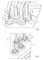
- the device for wall bushing shown in FIG. 1 is used to carry out a bundle 2 of Lines 4, here hydraulic lines, through a wall 3 of a body not shown Motor vehicle.
- the lines 4 are provided with line couplings 5, each consisting of a first Coupling half 6 and a second coupling half 7 exist. Sections 4a, 4b of the lines 4 are each connected to the coupling halves 6, 7.
- the first coupling halves 6 are through a holder 8 summarized.
- the first coupling halves 6 are in the wall 3 by rubber-elastic plugs 9 sealed and vibration isolated.
- the first Coupling halves 6 are laterally provided with flats 10, which between projections 11 of the holder 8th are included, so that the first coupling halves 6 are held in the holder 8 against rotation.
- Fig. 3 shows a line 4 with a line coupling 5 in the assembled state in section.
- the first Section 4a of line 4 - here a hose section - is through with the first coupling half 6 Plugged in connected.
- the second section 4b of the line 4 - here a pipe section - is through the second Coupling half 7, which in the present example is designed as a union nut, with the first Coupling half 6 connected.
- the wall 3 has openings 12, only one of which is shown here by way of example.
- the plug 9 buttoned which with the adjacent plug 9 'for the sake of Ease of assembly is connected via a web 13.
- the plug 9 is through a circumferential nose 14, which engages behind the opening 12, held in the opening 12.
- the first coupling half 6 is received with a cylindrical region 15 in the plug 9 in such a way that the plug 9 forms a seal between the wall 3 and the first coupling half 6. End of the cylindrical region 15, a circumferential nose 16 is provided, which is provided in the stopper Paragraph 17 engages. In this way, the first coupling half 6 is held in place in the stopper 9.
- the holder 8 is connected exclusively to the first coupling half 6 and has an opening 18 Inclusion of the first coupling half 6.
- the projections 11 are formed on the edge of the opening 18, which support the flats 10 of the first coupling half 6 and thus the first coupling half 6 secure against twisting.
- the snap ring 20 (in Fig. 5 in Top view) consists of a resilient material and has a gap.
- the snap ring 20 When inserting the the first coupling half 6 in the opening 18 of the holder 8, the snap ring 20 is supported by a Slant 21 compressed in the opening 18 and pressed into the groove 19. Reaches the first Coupling half 6 in the holder 8 their end position, the snap ring 20 can expand again and reach behind a shoulder 22 which is provided at the end of the opening 18. In this position the Snap ring 20, the first coupling half 6 and the holder 8 by positive locking.
- the snap ring 18 is bevelled on the outside corresponding to the bevel 21 to insert the Coupling half 6 and the associated compression of the snap ring 20 to facilitate.
- Fig. 4 shows the individual components of the wall bushing 1 without the wall 3 again in Overview in an exploded view.
- Fig. 6 shows a second embodiment of the device for the wall lead-through of the lines 4 a wall of a body of a motor vehicle, not shown here.
- the lines 4 are again provided with line couplings, of which only the first coupling halves 6a are shown here.
- two first coupling halves 6 are by one Holder 8a combined into a group; a total of 2 holders 8a are necessary to make one out of four Lines 4 summarize existing line bundle in groups of lines 4.
- the first coupling halves 6a are through in the wall rubber-elastic plug 9 kept sealed and vibration-isolated, the present Embodiment corresponding to the first coupling halves 6a also in a group of two Stopper 9 are summarized. There is no need for groups to start from Coupling halves 6a have the same number as the group of plugs 9; the group size oriented are rather the circumstances of the assembly of the respective components.
- first coupling halves 6a there is an anti-rotation device for each of the line couplings 5 separate plug 9 is provided, each in its own opening 12 (see FIG. 3) in the wall 3 is held.
- disks 23 are rotationally fixed, for example by soldering held, the discs 23 each carry a nose 24.
- Each nose 24 engages in a corresponding one
- a recess 25 is provided in the holder 8a, so that the first coupling halves 6a in the holder 8a are held against rotation.
- FIG. 7 shows a main section through one of the first coupling halves 6a of the second Embodiment. It can be clearly seen that the nose 24 engages in the recess 25.
- the further construction of the coupling halves 6a corresponds to the first embodiment, in particular the Locking the coupling halves 6a in the holder 8a with the help of the snap ring 20 and the locking of the Coupling halves 6a in the plug 9 by circumferential lugs 16 formed on the coupling halves 6a, which engage behind a paragraph 17 provided in the plug 9.
Landscapes
- Engineering & Computer Science (AREA)
- General Engineering & Computer Science (AREA)
- Mechanical Engineering (AREA)
- Transportation (AREA)
- Quick-Acting Or Multi-Walled Pipe Joints (AREA)
- Snaps, Bayonet Connections, Set Pins, And Snap Rings (AREA)
- Installation Of Indoor Wiring (AREA)
- Connector Housings Or Holding Contact Members (AREA)
Abstract
Description
Die Erfindung betrifft eine Vorrichtung zur Wanddurchführung von Rohrleitungen, Schläuchen oder
elektrischen Kabeln - nachfolgend zusammenfassend als Leitungen bezeichnet - für Kraftfahrzeuge nach
dem Oberbegriff des Patentanspruches 1.The invention relates to a device for wall penetration of pipes, hoses or
electrical cables - hereinafter referred to collectively as lines - for motor vehicles
the preamble of
Aus der DE 32 26 475 A1 ist bereits eine abdichtende Wanddurchführung für Rohrleitungen, Schläuche oder elektrische Kabel für Kraftfahrzeuge bekannt, bei der in den Leitungen Leitungskupplungen vorgesehen sind. Jeweils eine erste Kupplungshälfte dieser Leitungskupplungen ist in einer Abdeckplatte verdrehsicher und abdichtend festlegbar, die hierzu mit entsprechenden Durchgangsöffnungen versehen ist, in denen die ersten Kupplungshälften oder Blindstopfen verrastend gehalten sind. Auf diese Weise lassen sich auch Bündel von Leitungen abgedichtet durch eine Wandung der Karosserie hindurchführen. Außerdem ist die Montage der Leitungen vereinfacht, da diese vormontiert, angeschlossen und geprüft werden können.DE 32 26 475 A1 is already a sealing wall bushing for pipes, hoses or electrical cables for motor vehicles are known in which line couplings are provided in the lines are. A first coupling half of these line couplings is secured against rotation in a cover plate and sealingly fixable, which is provided with corresponding through openings in which the first coupling halves or blind plugs are held in place. This way too Pass bundles of cables through a sealed wall of the body. Besides, that is Installation of the cables is simplified because they can be pre-assembled, connected and checked.
Ausgehend von diesem Stand der Technik liegt der Erfindung die Aufgabe zugrunde, eine Vorrichtung zur Wanddurchführung von Rohrleitungen, Schläuchen oder elektrischen Kabeln zu schaffen, die hinsichtlich ihrer Montage weiter vereinfacht ist.Based on this prior art, the invention has for its object a device for Wall ducting of pipes, hoses or electrical cables to create the respect their assembly is further simplified.
Diese Aufgabe wird erfindungsgemäß mit den Merkmalen des Patentanspruches 1 gelöst. Erfindungsgemäß
wird vorgeschlagen, die ersten Kupplungshälften der Leitungskupplungen jeweils durch einen Halter in
wenigstens eine Gruppe zu wenigstens zwei ersten Kupplungshälften zusammenzufassen und die derart
gebündelten Kupplungshälften in Stopfen zu halten, die in Öffnungen einer Wandung angeordnet sind. Durch
die Zusammenfassung der ersten Kupplungshälften mit Hilfe des Halters kann ein in das Fahrzeug
einzubauendes Modul einschließlich seiner Leitungen außerhalb des Fahrzeuges vormontiert, geprüft und
zur Montage vorbereitet werden. Durch die Gruppierung der Kupplungshälften sind diese Arbeiten wie auch
die nachfolgende Montage der Kupplungshälften in die Wandöffnungen erleichtert. Die Montage der
Kupplungshälften in die Wandöffnungen ist insbesondere dann erleichtert, wenn kein Sichtkontakt zu den
Wandöffnungen bei der Montage der Leitungen möglich ist. Dadurch, dass für jede Kupplungshälfte eine
eigene Öffnung in der Wandung der Karosserie angebracht ist, ist diese Öffnung in der Regel als
kreisförmige Öffnung einfach anzubringen, gut abdichtbar und im übrigen an unterschiedliche
Fahrzeugvarianten mit einer unterschiedlichen Zahl von Leitungen einfach anzupassen.This object is achieved with the features of
Erfindungsgemäße Weiterbildungen der Erfindung sind in den Unteransprüchen beschrieben.Further developments of the invention according to the invention are described in the subclaims.
So wird vorgeschlagen, dass die Stopfen aus gummielastischem Material bestehen und in Gruppen zusammengefasst sind. Durch die Verwendung des gummielastischen Materiales werden die Kupplungshälften in vorteilhafter Weise schwingungstechnisch gegenüber der Wandung isoliert, so dass die Leitungen gegenüber der Karosserie des Fahrzeuges schwingungsentkoppelt gehalten und durch die Wandung hindurchgeführt sind. Druckschwankungen und andere Schwingungen in den Leitungen führen damit nicht mehr zu einer Schwingungsanregung der Wandung, die im Innenraum des Fahrzeuges deutlich zu hören wären. Durch das Zusammenfassen der Stopfen in Gruppen werden Herstellung und Montage des Stopfen vereinfacht, da alle für eine Wanddurchführung benötigten Stopfen zu einem Teil zusammengefasst werden können. Gleichzeitig aber bleibt die Einzelabdichtung jeder Kupplungshälfte dadurch gewährleistet, dass in jeder Wandöffnung ein separater Stopfen vorgesehen ist. Wenn, wie weiter vorgeschlagen, die Stopfen mit einem Absatz versehen sind, der mit einem an der ersten Kupplungshälfte vorgesehenen Vorsprung rastend zusammenwirkt, sind außer dem Stopfen keine weiteren Mittel erforderlich, um die ersten Kupplungshälften in der Wandungsöffnung sicher und abgedichtet festzulegen.It is suggested that the plugs are made of rubber-elastic material and in groups are summarized. By using the rubber-elastic material Coupling halves in an advantageous manner vibration isolated from the wall, so that the Lines kept decoupled from the body of the vehicle vibration and through the Wall are passed. Pressure fluctuations and other vibrations in the lines thus no longer a vibration excitation of the wall, which is clear in the interior of the vehicle would be heard. By grouping the plugs in groups, the manufacture and assembly of the Plug simplified because all the plugs required for a wall duct are combined into one part can be. At the same time, however, the individual sealing of each coupling half is guaranteed that a separate plug is provided in each wall opening. If, as further suggested, the Stopper are provided with a shoulder that with a provided on the first coupling half Interlocking together, no other means are required to stop the the first coupling halves in the wall opening securely and sealed.
Schließlich wird vorgeschlagen, zur Verbindung der ersten Kupplungshälften mit dem Halter einen Sprengring vorzusehen, der in eine außenseits an der ersten Kupplungshälfte angebrachten Nut eingelegt ist. Korrespondierend zu dieser ersten Nut ist in den Öffnungen, die im Halter zur Aufnahme der ersten Kupplungshälfte vorgesehen sind, jeweils eine zweite Nut angebracht. Wenn die erste Kupplungshälfte in die Öffnung eingeschoben wird, wird der Sprengring zunächst zusammengedrückt. Erreicht die erste Kupplungshälfte ihre endgültige Position, so kann sich der Sprengring wieder ausdehnen und in die zweite Nut eingreifen. Dadurch, dass der Sprengring nun zwischen erster Nut und zweiter Nut zu liegen kommt, ist die erste Kupplungshälfte mit dem Halter verbunden.Finally, it is proposed to connect the first coupling halves to the holder To provide a snap ring, which is inserted in a groove on the outside of the first coupling half is. Corresponding to this first groove is in the openings in the holder for receiving the first Coupling half are provided, each have a second groove attached. If the first coupling half in the Opening is pushed in, the snap ring is first pressed together. Reaches the first Coupling half their final position, the snap ring can expand again and into the second Engage the groove. Because the snap ring now comes to rest between the first groove and the second groove the first coupling half connected to the holder.
Insbesondere dann, wenn die beiden Kupplungshälften der Leitungskupplung durch Schrauben miteinander verbunden werden sollen, ist es notwendig die ersten Kupplungshälften im Halter verdrehgesichert zu halten. Dazu sind die ersten Kupplungshälften beispielsweise mit einem Sechskant oder Abflachungen versehen, die sich dann an korrespondierenden Anlageflächen an der Halterung abstützen.Especially when the two coupling halves of the line coupling are screwed together to be connected, it is necessary to lock the first coupling halves in the holder so that they cannot rotate hold. For this purpose, the first coupling halves are, for example, with a hexagon or flats provided, which are then supported on corresponding contact surfaces on the bracket.
Die Erfindung ist nachstehend anhand des in den Figuren dargestellten Ausführungsbeispieles näher erläutertThe invention is described in more detail below on the basis of the exemplary embodiment shown in the figures explained
Es zeigen:
- Fig. 1
- eine Vorderansicht einer erfindungsgemäßen Vorrichtung zur Wanddurchführung,
- Fig. 2
- eine Rückansicht der Vorrichtung zur Wanddurchführung,
- Fig. 3
- einen Schnitt nach der Ebene X der Fig. 1,
- Fig. 4
- eine Explosionsdarstellung der Vorrichtung zur Wanddurchführung ohne Wandung,
- Fig. 5
- eine Aufsicht auf einen Sprengring,
- Fig. 6
- ein zweites Ausführungsbeispiel der Vorrichtung zur Wanddurchführung,
- Fig. 7
- einen Hauptschnitt zu Fig. 6,
- Fig. 8
- eine Explosionsdarstellung von oben zu Fig. 6, und
- Fig. 9
- eine Explosionsdarstellung von unten zu Fig. 6.
- Fig. 1
- 2 shows a front view of a device for wall penetration according to the invention,
- Fig. 2
- a rear view of the device for wall penetration,
- Fig. 3
- 2 shows a section along the plane X of FIG. 1,
- Fig. 4
- an exploded view of the device for wall penetration without wall,
- Fig. 5
- a supervision of a snap ring,
- Fig. 6
- a second embodiment of the device for wall penetration,
- Fig. 7
- a main section of Fig. 6,
- Fig. 8
- an exploded view from above to Fig. 6, and
- Fig. 9
- 6 shows an exploded view from below of FIG. 6.
Die in Fig. 1 gezeigte Vorrichtung zur Wanddurchführung dient zur Durchführung eines Bündels 2 von
Leitungen 4, hier Hydraulikleitungen, durch eine Wandung 3 einer Karosserie eines nicht näher gezeigten
Kraftfahrzeuges. Die Leitungen 4 sind mit Leitungskupplungen 5 versehen, die jeweils aus einer ersten
Kupplungshälfte 6 und einer zweiten Kupplungshälfte 7 bestehen. Abschnitte 4a, 4b der Leitungen 4 sind
jeweils mit den Kupplungshälften 6, 7 verbunden. Die ersten Kupplungshälften 6 sind durch einen Halter 8
zusammengefasst. Die ersten Kupplungshälften 6 sind in der Wandung 3 durch gummielastischen Stopfen
9 dichtend und schwingungsisoliert gehalten. Für jede der Leitungskupplungen 5 ist ein eigener Stopfen 9
vorgesehen, der jeweils in einer eigenen Öffnung 12 (siehe Fig. 3) in der Wandung 3 gehalten ist. Die ersten
Kupplungshälften 6 sind seitlich mit Abflachungen 10 versehen, die zwischen Vorsprüngen 11 des Halters 8
aufgenommen sind, so dass die ersten Kupplungshälften 6 im Halter 8 verdrehsicher gehalten sind.The device for wall bushing shown in FIG. 1 is used to carry out a
Fig. 3 zeigt eine Leitung 4 mit einer Leitungskupplung 5 im montierten Zustand im Schnitt. Der erste
Abschnitt 4a der Leitung 4 - hier ein Schlauchabschnitt - ist mit der ersten Kupplungshälfte 6 durch
Aufstecken verbunden. Der zweite Abschnitt 4b der Leitung 4 - hier ein Rohrabschnitt - ist durch die zweite
Kupplungshälfte 7, die im vorliegenden Beispiel als Überwurfmutter ausgebildet ist, mit der ersten
Kupplungshälfte 6 verbunden.Fig. 3 shows a line 4 with a
Die Wandung 3 weist Öffnungen 12 auf, von denen hier nur eine einzige beispielhaft dargestellt ist. In der
Öffnung 12 ist der Stopfen 9 eingeknöpft, der mit dem benachbarten Stopfen 9' aus Gründen der
Montageerleichterung über einen Steg 13 verbunden ist. Der Stopfen 9 ist durch eine umlaufende Nase 14,
die die Öffnung 12 hintergreift, in der Öffnung 12 gehalten.The
Die erste Kupplungshälfte 6 ist mit einem zylindrischen Bereich 15 so im Stopfen 9 aufgenommen, dass
der Stopfen 9 eine Dichtung zwischen der Wandung 3 und der ersten Kupplungshälfte 6 bildet. Endseits des
zylindrischen Bereiches 15 ist eine umlaufende Nase 16 vorgesehen, die einen im Stopfen vorgesehenen
Absatz 17 hintergreift. Auf diese Weise ist die erste Kupplungshälfte 6 rastend im Stopfen 9 gehalten.The
Der Halter 8 ist ausschließlich mit der ersten Kupplungshälfte 6 verbunden und weist eine Öffnung 18 zur
Aufnahme der ersten Kupplungshälfte 6 auf. Am Rand der Öffnung 18 sind die Vorsprünge 11 ausgeformt,
die die Abflachungen 10 der ersten Kupplungshälfte 6 abstützen und damit die erste Kupplungshälfte 6
gegen Verdrehen sichern. The
Zur Verriegelung der ersten Kupplungshälfte 6 im Halter 8 ist in die erste Kupplungshälfte 6 eine
umlaufende Nut 19 eingearbeitet, in die ein Sprengring 20 eingelegt ist. Der Sprengring 20 (in Fig. 5 in
Aufsicht dargestellt) besteht aus einem federnden Material und weist eine Lücke auf. Beim Einschieben der
ersten Kupplungshälfte 6 in die Öffnung 18 des Halters 8 wird der Sprengring 20 unterstützt von einer
Schräge 21 in der Öffnung 18 zusammengedrückt und in die Nut 19 gepresst. Erreicht die erste
Kupplungshälfte 6 im Halter 8 ihre Endposition, so kann der Sprengring 20 sich wieder ausdehnen und
einen Absatz 22 hintergreifen, der endseits der Öffnung 18 vorgesehen ist. In dieser Position verbindet der
Sprengring 20 die erste Kupplungshälfte 6 und den Halter 8 durch Formschluss. Im dargestellten Beispiel
ist der Sprengring 18 außenseits korrespondierend zur Schräge 21 angeschrägt, um das Einführen der
Kupplungshälfte 6 und das damit verbundene Zusammenpressen des Sprengringes 20 zu erleichtern.To lock the
Fig. 4 zeigt die einzelnen Komponenten der Wanddurchführung 1 ohne die Wandung 3 nochmals im
Überblick in einer Explosionsdarstellung.Fig. 4 shows the individual components of the
Zur Montage werden zunächst die Teile 4a der Leitungen mit den ersten Kupplungshälften 6 versehen. Die
ersten Kupplungshälften 6 werden dann soweit in den Halter 8 eingedrückt, bis die Sprengringe 20
verrasten. Das Rohrbündel ist nun endseits durch den Halter 8 zu einer Einheit zusammen gefasst.
Unabhängig hiervon werden die Stopfen 9 in Öffnungen 12 der Wandung 3 eingeknöpft.For assembly,
Die eigentliche Montage des Rohrbündels 2 erfolgt nun in der Weise, dass die durch den Halter 8
zusammengefassten ersten Kupplungshälften 6 in die jeweiligen Stopfen 9 so weit eingedrückt werden, bis
sie dort mit ihrem umlaufenden Vorsprung 17 verrasten. Von der anderen Seite der Wandung 3 kann nun in
einem späteren Arbeitsschritt die zweiten Teilstücke 4b montiert werden, in dem die zweite Kupplungshälfte
7 in der ersten Kupplungshälfte 6 befestigt wird.The actual assembly of the
Fig. 6 zeigt ein zweites Ausführungsbeispiel der Vorrichtung zur Wanddurchführung der Leitungen 4 durch
eine hier nicht dargestellte Wandung einer Karosserie eines Kraftfahrzeuges. Die Leitungen 4 sind wiederum
mit Leitungskupplungen versehen, von der hier nur die ersten Kupplungshälften 6a gezeigt sind. lm
Unterschied zum ersten Ausführungsbeispiel sind hier zwei erste Kupplungshälften 6 sind durch den einen
Halter 8a zu einer Gruppe zusammengefasst; insgesamt sind 2 Halter 8a notwendig, um ein aus vier
Leitungen 4 bestehendes Leitungsbündel in Gruppen von Leitungen 4 zusammenzufassen.Fig. 6 shows a second embodiment of the device for the wall lead-through of the
Wie im ersten Ausführungsbeispiel sind die ersten Kupplungshälften 6a in der Wandung durch
gummielastischen Stopfen 9 dichtend und schwingungsisoliert gehalten, die im vorliegenden
Ausführungsbeispiel korrespondierend zu den ersten Kupplungshälften 6a ebenfalls in einer Gruppe zu zwei
Stopfen 9 zusammengefasst sind. Es besteht keine Notwendigkeit, dass die Gruppen von ersten
Kupplungshälften 6a dieselbe Anzahl aufweist wie die Gruppe von Stopfen 9; die Gruppengröße orientiert
sind vielmehr an den Gegebenheiten bei der Montage der jeweiligen Bauteile.As in the first exemplary embodiment, the
An den ersten Kupplungshälften 6a sind zur Verdrehsicherung Für jede der Leitungskupplungen 5 ist ein
eigener Stopfen 9 vorgesehen, der jeweils in einer eigenen Öffnung 12 (siehe Fig. 3) in der Wandung 3
gehalten ist. An den ersten Kupplungshälften 6a sind Scheiben 23 beispielsweise durch Löten drehfest
gehalten, wobei die Scheiben 23 jeweils eine Nase 24 tragen. Jede Nase 24 greift in eine entsprechende
Ausnehmung 25 ein, die im Halter 8a vorgesehen ist, so dass die ersten Kupplungshälften 6a im Halter 8a
verdrehsicher gehalten sind.On the
Fig. 7 stellt einen Hauptschnitt durch eine der ersten Kupplungshälften 6a des zweiten
Ausführungsbeispieles dar. Deutlich zu erkennen ist, dass die Nase 24 in die Ausnehmung 25 eingreift. Der
weitere Aufbau der Kupplungshälften 6a entspricht dem ersten Ausführungsbeispiel, insbesondere die
Verrastung der Kupplungshälften 6a im Halter 8a mit Hilfe des Sprengringes 20 und die Verrastung der
Kupplungshälften 6a im Stopfen 9 durch an den Kupplungshälften 6a ausgebildete umlaufende Nasen 16,
die einen im Stopfen 9 vorgesehenen Absatz 17 hintergreifen.7 shows a main section through one of the
Fig. 8 und Fig. 9 zeigen das zweite Ausführungsbeispiel nochmals im Überblick in einer Explosionsdarstellung.FIGS. 8 and 9 show an overview of the second exemplary embodiment in one Exploded view.
Claims (4)
dadurch gekennzeichnet, dass
characterized in that
Applications Claiming Priority (2)
| Application Number | Priority Date | Filing Date | Title |
|---|---|---|---|
| DE10233127 | 2002-07-20 | ||
| DE10233127A DE10233127C1 (en) | 2002-07-20 | 2002-07-20 | Supply line or cable gland for automobile assembled from 2 coupling halves with holder securing first coupling halves of at least 2 glands together to provide installation module |
Publications (3)
| Publication Number | Publication Date |
|---|---|
| EP1382894A2 true EP1382894A2 (en) | 2004-01-21 |
| EP1382894A3 EP1382894A3 (en) | 2004-03-31 |
| EP1382894B1 EP1382894B1 (en) | 2009-08-19 |
Family
ID=29432741
Family Applications (1)
| Application Number | Title | Priority Date | Filing Date |
|---|---|---|---|
| EP03009688A Expired - Lifetime EP1382894B1 (en) | 2002-07-20 | 2003-04-30 | Wall feedthrough for pipes, hoses or electric cables for motor vehicles |
Country Status (3)
| Country | Link |
|---|---|
| US (1) | US7083202B2 (en) |
| EP (1) | EP1382894B1 (en) |
| DE (2) | DE10233127C1 (en) |
Cited By (3)
| Publication number | Priority date | Publication date | Assignee | Title |
|---|---|---|---|---|
| DE202009009807U1 (en) | 2009-07-17 | 2009-09-24 | Wiska Hoppmann & Mulsow Gmbh | Tamper-proof cable entry |
| EP2055535B2 (en) † | 2007-10-30 | 2014-10-22 | LEONI Bordnetz-Systeme GmbH | Cable set, especially a high voltage cable set for a motor vehicle, and device to implement an electric cable and to connect a cable screen |
| DE102013214611A1 (en) * | 2013-07-26 | 2015-01-29 | Bayerische Motoren Werke Aktiengesellschaft | Coupling system for forming at least one arranged in a vehicle fluid-carrying line |
Families Citing this family (38)
| Publication number | Priority date | Publication date | Assignee | Title |
|---|---|---|---|---|
| US7029238B1 (en) * | 1998-11-23 | 2006-04-18 | Mykrolis Corporation | Pump controller for precision pumping apparatus |
| US8172546B2 (en) | 1998-11-23 | 2012-05-08 | Entegris, Inc. | System and method for correcting for pressure variations using a motor |
| US20060038074A1 (en) | 2004-05-07 | 2006-02-23 | Buhr Theo D | Connecting element for connecting a conduit system to cooling aggregates in aircraft cabins |
| DE102004023242B4 (en) * | 2004-05-07 | 2007-06-14 | Airbus Deutschland Gmbh | Connection element for connecting two line elements of a guided through a separator to the cabin of an aircraft conduit system |
| DE102004033567A1 (en) * | 2004-07-09 | 2006-01-26 | Leybold Optics Gmbh | Consumer supply connection system for implementing electric output/power and a fluid through a wall of a chamber in a vacuum chamber supplies a consumer with power via a supply module |
| KR101212824B1 (en) | 2004-11-23 | 2012-12-14 | 엔테그리스, 아이엔씨. | System and method for a variable home position dispense system |
| DE102005055046A1 (en) * | 2005-11-16 | 2007-05-24 | J. Eberspächer GmbH & Co. KG | Crosstalk for an exhaust system |
| US8753097B2 (en) | 2005-11-21 | 2014-06-17 | Entegris, Inc. | Method and system for high viscosity pump |
| JP5339914B2 (en) | 2005-11-21 | 2013-11-13 | インテグリス・インコーポレーテッド | System and method for a pump having reduced form factor |
| US8025486B2 (en) | 2005-12-02 | 2011-09-27 | Entegris, Inc. | System and method for valve sequencing in a pump |
| WO2007067339A2 (en) * | 2005-12-02 | 2007-06-14 | Entegris, Inc. | Fixed volume valve system |
| US8083498B2 (en) | 2005-12-02 | 2011-12-27 | Entegris, Inc. | System and method for position control of a mechanical piston in a pump |
| US7878765B2 (en) | 2005-12-02 | 2011-02-01 | Entegris, Inc. | System and method for monitoring operation of a pump |
| US7547049B2 (en) * | 2005-12-02 | 2009-06-16 | Entegris, Inc. | O-ring-less low profile fittings and fitting assemblies |
| JP4845969B2 (en) | 2005-12-02 | 2011-12-28 | エンテグリース,インコーポレイテッド | I / O system, method, and apparatus for coupling pump controller |
| US8029247B2 (en) | 2005-12-02 | 2011-10-04 | Entegris, Inc. | System and method for pressure compensation in a pump |
| US7850431B2 (en) | 2005-12-02 | 2010-12-14 | Entegris, Inc. | System and method for control of fluid pressure |
| KR101308175B1 (en) | 2005-12-05 | 2013-09-26 | 엔테그리스, 아이엔씨. | A method for compensating for errors in dispense volumes, a multi-stage pump, and a method for compensating for system compliance |
| DE102006002564A1 (en) * | 2006-01-05 | 2007-07-12 | Alfred Kärcher Gmbh & Co. Kg | Plug-in part for connector arrangement |
| DE102006002565A1 (en) * | 2006-01-05 | 2007-07-12 | Alfred Kärcher Gmbh & Co. Kg | Coupling part for connector assembly |
| TWI402423B (en) | 2006-02-28 | 2013-07-21 | Entegris Inc | System and method for operation of a pump |
| US7684446B2 (en) * | 2006-03-01 | 2010-03-23 | Entegris, Inc. | System and method for multiplexing setpoints |
| US7494265B2 (en) | 2006-03-01 | 2009-02-24 | Entegris, Inc. | System and method for controlled mixing of fluids via temperature |
| SE530621C2 (en) * | 2006-12-01 | 2008-07-22 | Nordhydraulic Ab | Hydraulic connection |
| SE530620C2 (en) * | 2006-12-01 | 2008-07-22 | Nordhydraulic Ab | Parking means for hydraulic coupling |
| DE202007012400U1 (en) * | 2007-04-19 | 2008-08-21 | Voss Automotive Gmbh | Connecting device for media lines in the region of a wall duct and wall element |
| WO2009041865A1 (en) * | 2007-09-26 | 2009-04-02 | Volvo Lastvagnar Ab | A drive unit for a heavy vehicle |
| DE102008014291A1 (en) | 2008-03-14 | 2009-09-24 | Agco Gmbh | Vibration decoupling device for hydraulics |
| DE202008005929U1 (en) * | 2008-04-29 | 2009-09-03 | Voss Automotive Gmbh | Connecting device for media lines in the region of a wall duct and wall element |
| DE102008029468B4 (en) | 2008-06-20 | 2011-01-13 | Airbus Operations Gmbh | Interface element, aircraft interior equipment component and method for assembling an aircraft interior equipment component |
| FR2938039A1 (en) * | 2008-10-31 | 2010-05-07 | Peugeot Citroen Automobiles Sa | Sealed connection assembly for connecting connector to e.g. wall of brake control enclosure of pneumatic brake booster in vehicle, has sleeve including outer wall with notches ensuring sealed anchoring of sleeve on endpiece |
| US20110103882A1 (en) * | 2009-11-03 | 2011-05-05 | Mcdavid Bradford A | Pipe flange guide shroud |
| US8511717B2 (en) * | 2011-06-30 | 2013-08-20 | Harley-Davidson Motor Company Group, LLC | Poka-yoke for a set of hydraulic fittings |
| KR101211637B1 (en) * | 2011-12-12 | 2012-12-18 | 주식회사 화승알앤에이 | Double pipe heat exchanger having multi-directional connector and air conditioner for vehicle having the same |
| DE102018205611A1 (en) * | 2018-04-13 | 2019-10-17 | Volkswagen Aktiengesellschaft | Housing with a cable feedthrough element and method for attaching a sensor cable to a housing of a motor vehicle steering |
| US11293430B2 (en) * | 2020-01-22 | 2022-04-05 | DropWater Solutions | Smart pump controller |
| US11959816B2 (en) | 2020-01-22 | 2024-04-16 | DropWater Solutions | Multi-bandwidth communication for fluid distribution network |
| US11792885B2 (en) | 2020-01-22 | 2023-10-17 | DropWater Solutions | Wireless mesh for fluid distribution network |
Citations (1)
| Publication number | Priority date | Publication date | Assignee | Title |
|---|---|---|---|---|
| DE3226475A1 (en) | 1982-07-15 | 1984-01-19 | Daimler-Benz Ag, 7000 Stuttgart | SEALING WALL PIPE FOR PIPELINES, HOSES OR ELECTRIC CABLES FOR MOTOR VEHICLES |
Family Cites Families (11)
| Publication number | Priority date | Publication date | Assignee | Title |
|---|---|---|---|---|
| US3869152A (en) * | 1974-03-27 | 1975-03-04 | Gen Motors Corp | Tube mounting assembly |
| US3869153A (en) * | 1974-07-22 | 1975-03-04 | Gen Motors Corp | Double tube mounting assembly |
| US4482172A (en) * | 1981-07-09 | 1984-11-13 | Eaton Corporation | Dual sealing fluid connector |
| US4630847A (en) * | 1984-10-05 | 1986-12-23 | Colder Products Company | Multiple tube connector |
| US4893845A (en) * | 1988-04-18 | 1990-01-16 | Proprietary Technology, Inc. | Firewall heater line adapter |
| DE4138064C1 (en) * | 1991-11-19 | 1993-05-06 | Kreuzer Gmbh + Co Ohg, 8039 Puchheim, De | |
| JP3508381B2 (en) * | 1996-04-26 | 2004-03-22 | 東海ゴム工業株式会社 | One-touch connection device for focusing hose |
| US5730121A (en) * | 1996-07-19 | 1998-03-24 | Hawkins, Jr.; Albert D. | Emergency air system |
| US5951059A (en) * | 1996-07-24 | 1999-09-14 | Tokai Rubber Industries Ltd. | Tube connector device having connector holder made of elastomer |
| US6520545B2 (en) * | 2000-12-08 | 2003-02-18 | Sartorius Ag | Fluid connection adapter assembly |
| US6609732B1 (en) * | 2002-02-01 | 2003-08-26 | General Motors Corporation | Quick connect multi-hose connector |
-
2002
- 2002-07-20 DE DE10233127A patent/DE10233127C1/en not_active Expired - Fee Related
-
2003
- 2003-04-30 DE DE50311821T patent/DE50311821D1/en not_active Expired - Lifetime
- 2003-04-30 EP EP03009688A patent/EP1382894B1/en not_active Expired - Lifetime
- 2003-07-21 US US10/622,643 patent/US7083202B2/en not_active Expired - Lifetime
Patent Citations (1)
| Publication number | Priority date | Publication date | Assignee | Title |
|---|---|---|---|---|
| DE3226475A1 (en) | 1982-07-15 | 1984-01-19 | Daimler-Benz Ag, 7000 Stuttgart | SEALING WALL PIPE FOR PIPELINES, HOSES OR ELECTRIC CABLES FOR MOTOR VEHICLES |
Cited By (4)
| Publication number | Priority date | Publication date | Assignee | Title |
|---|---|---|---|---|
| EP2055535B2 (en) † | 2007-10-30 | 2014-10-22 | LEONI Bordnetz-Systeme GmbH | Cable set, especially a high voltage cable set for a motor vehicle, and device to implement an electric cable and to connect a cable screen |
| DE202009009807U1 (en) | 2009-07-17 | 2009-09-24 | Wiska Hoppmann & Mulsow Gmbh | Tamper-proof cable entry |
| DE102010031345A1 (en) | 2009-07-17 | 2011-01-20 | Wiska Hoppmann & Mulsow Gmbh | Tamper-proof cable entry |
| DE102013214611A1 (en) * | 2013-07-26 | 2015-01-29 | Bayerische Motoren Werke Aktiengesellschaft | Coupling system for forming at least one arranged in a vehicle fluid-carrying line |
Also Published As
| Publication number | Publication date |
|---|---|
| US7083202B2 (en) | 2006-08-01 |
| EP1382894A3 (en) | 2004-03-31 |
| DE10233127C1 (en) | 2003-12-11 |
| DE50311821D1 (en) | 2009-10-01 |
| US20040037627A1 (en) | 2004-02-26 |
| EP1382894B1 (en) | 2009-08-19 |
Similar Documents
| Publication | Publication Date | Title |
|---|---|---|
| DE10233127C1 (en) | Supply line or cable gland for automobile assembled from 2 coupling halves with holder securing first coupling halves of at least 2 glands together to provide installation module | |
| DE4434202A1 (en) | Cable lead-through strip | |
| EP3266084A1 (en) | Cable seal | |
| EP3329566B1 (en) | Explosion-proof assembly and method for producing same | |
| EP1134472B1 (en) | Sealing element for a fire barrier device for the passage of conduits through openings in walls | |
| DE102015112284A1 (en) | Explosion-proof arrangement and method for the production thereof | |
| DE102015007404A1 (en) | LEITUNGSAUFNEHMER | |
| EP1097496B1 (en) | Sealing element for cable fittings | |
| EP1867024A1 (en) | Cable bushing device | |
| EP2688169A1 (en) | Cable feedthrough | |
| EP2447583B1 (en) | Sealing device | |
| EP2735058B1 (en) | Cable connection component | |
| WO2012045430A2 (en) | Cable termination device | |
| EP0695008B1 (en) | Universal cable clamping device | |
| DE10349440B4 (en) | Dense wall penetration with strain relief | |
| EP1289087A2 (en) | Closing and sealing element | |
| DE19908657C1 (en) | Switch cabinet cable opening sealing device has 2 cooperating housing halves brought together to compress sealing element fitted around outside of cable fitted through cable opening | |
| EP1484544A1 (en) | Conduit feed-through for the installation of a sanitary tube through a wall | |
| DE29518214U1 (en) | Cable gland | |
| DE102016104477A1 (en) | shower hose | |
| DE102008011978A1 (en) | Screw connection for sealed line duct, has cover with outer windings, and clamping screw screwed on end of cover, where clamping screw has axial channel opening between cover and clamping screw inserting in clamping part and sealing part | |
| EP0584616A2 (en) | Assembly for a plurality of cable entries for cable sleeves | |
| DE19743185A1 (en) | Multiple connector for pipelines | |
| DE2012631A1 (en) | Longitudinally split cable sleeve with cable clamp | |
| EP3492796B1 (en) | Connection system for repairing plastic composite pipe systems |
Legal Events
| Date | Code | Title | Description |
|---|---|---|---|
| PUAI | Public reference made under article 153(3) epc to a published international application that has entered the european phase |
Free format text: ORIGINAL CODE: 0009012 |
|
| AK | Designated contracting states |
Kind code of ref document: A2 Designated state(s): AT BE BG CH CY CZ DE DK EE ES FI FR GB GR HU IE IT LI LU MC NL PT RO SE SI SK TR |
|
| AX | Request for extension of the european patent |
Extension state: AL LT LV MK |
|
| PUAL | Search report despatched |
Free format text: ORIGINAL CODE: 0009013 |
|
| RIC1 | Information provided on ipc code assigned before grant |
Ipc: 7F 16L 5/08 B Ipc: 7F 16L 5/02 A Ipc: 7F 16L 5/06 B |
|
| AK | Designated contracting states |
Kind code of ref document: A3 Designated state(s): AT BE BG CH CY CZ DE DK EE ES FI FR GB GR HU IE IT LI LU MC NL PT RO SE SI SK TR |
|
| AX | Request for extension of the european patent |
Extension state: AL LT LV MK |
|
| 17P | Request for examination filed |
Effective date: 20040930 |
|
| AKX | Designation fees paid |
Designated state(s): DE ES FR GB IT SE |
|
| 17Q | First examination report despatched |
Effective date: 20071016 |
|
| RAP1 | Party data changed (applicant data changed or rights of an application transferred) |
Owner name: DR. ING. H.C. F. PORSCHE AKTIENGESELLSCHAFT |
|
| RAP1 | Party data changed (applicant data changed or rights of an application transferred) |
Owner name: DR. ING. H.C. F. PORSCHE AKTIENGESELLSCHAFT |
|
| GRAC | Information related to communication of intention to grant a patent modified |
Free format text: ORIGINAL CODE: EPIDOSCIGR1 |
|
| GRAP | Despatch of communication of intention to grant a patent |
Free format text: ORIGINAL CODE: EPIDOSNIGR1 |
|
| GRAS | Grant fee paid |
Free format text: ORIGINAL CODE: EPIDOSNIGR3 |
|
| GRAA | (expected) grant |
Free format text: ORIGINAL CODE: 0009210 |
|
| AK | Designated contracting states |
Kind code of ref document: B1 Designated state(s): DE ES FR GB IT SE |
|
| REG | Reference to a national code |
Ref country code: GB Ref legal event code: FG4D Free format text: NOT ENGLISH |
|
| REF | Corresponds to: |
Ref document number: 50311821 Country of ref document: DE Date of ref document: 20091001 Kind code of ref document: P |
|
| PG25 | Lapsed in a contracting state [announced via postgrant information from national office to epo] |
Ref country code: SE Free format text: LAPSE BECAUSE OF FAILURE TO SUBMIT A TRANSLATION OF THE DESCRIPTION OR TO PAY THE FEE WITHIN THE PRESCRIBED TIME-LIMIT Effective date: 20090819 Ref country code: ES Free format text: LAPSE BECAUSE OF FAILURE TO SUBMIT A TRANSLATION OF THE DESCRIPTION OR TO PAY THE FEE WITHIN THE PRESCRIBED TIME-LIMIT Effective date: 20091130 |
|
| PLBE | No opposition filed within time limit |
Free format text: ORIGINAL CODE: 0009261 |
|
| STAA | Information on the status of an ep patent application or granted ep patent |
Free format text: STATUS: NO OPPOSITION FILED WITHIN TIME LIMIT |
|
| 26N | No opposition filed |
Effective date: 20100520 |
|
| GBPC | Gb: european patent ceased through non-payment of renewal fee |
Effective date: 20100430 |
|
| REG | Reference to a national code |
Ref country code: FR Ref legal event code: TP |
|
| PG25 | Lapsed in a contracting state [announced via postgrant information from national office to epo] |
Ref country code: IT Free format text: LAPSE BECAUSE OF FAILURE TO SUBMIT A TRANSLATION OF THE DESCRIPTION OR TO PAY THE FEE WITHIN THE PRESCRIBED TIME-LIMIT Effective date: 20090819 Ref country code: GB Free format text: LAPSE BECAUSE OF NON-PAYMENT OF DUE FEES Effective date: 20100430 |
|
| PGFP | Annual fee paid to national office [announced via postgrant information from national office to epo] |
Ref country code: FR Payment date: 20110510 Year of fee payment: 9 |
|
| REG | Reference to a national code |
Ref country code: FR Ref legal event code: ST Effective date: 20121228 |
|
| PG25 | Lapsed in a contracting state [announced via postgrant information from national office to epo] |
Ref country code: FR Free format text: LAPSE BECAUSE OF NON-PAYMENT OF DUE FEES Effective date: 20120430 |
|
| PGFP | Annual fee paid to national office [announced via postgrant information from national office to epo] |
Ref country code: DE Payment date: 20160405 Year of fee payment: 14 |
|
| REG | Reference to a national code |
Ref country code: DE Ref legal event code: R119 Ref document number: 50311821 Country of ref document: DE |
|
| PG25 | Lapsed in a contracting state [announced via postgrant information from national office to epo] |
Ref country code: DE Free format text: LAPSE BECAUSE OF NON-PAYMENT OF DUE FEES Effective date: 20171103 |