EP1382858A1 - Procédé de répartition d'aubes de rotor de turbomachine - Google Patents
Procédé de répartition d'aubes de rotor de turbomachine Download PDFInfo
- Publication number
- EP1382858A1 EP1382858A1 EP03291757A EP03291757A EP1382858A1 EP 1382858 A1 EP1382858 A1 EP 1382858A1 EP 03291757 A EP03291757 A EP 03291757A EP 03291757 A EP03291757 A EP 03291757A EP 1382858 A1 EP1382858 A1 EP 1382858A1
- Authority
- EP
- European Patent Office
- Prior art keywords
- blades
- static
- distributing
- moments
- determined value
- Prior art date
- Legal status (The legal status is an assumption and is not a legal conclusion. Google has not performed a legal analysis and makes no representation as to the accuracy of the status listed.)
- Granted
Links
- 238000000034 method Methods 0.000 title claims abstract description 20
- 230000003068 static effect Effects 0.000 claims abstract description 51
- 238000005259 measurement Methods 0.000 abstract description 7
- 238000010187 selection method Methods 0.000 abstract 1
- 230000000295 complement effect Effects 0.000 description 2
- 230000000694 effects Effects 0.000 description 2
- 230000005484 gravity Effects 0.000 description 2
- 230000006399 behavior Effects 0.000 description 1
- 238000010276 construction Methods 0.000 description 1
- 230000006378 damage Effects 0.000 description 1
- 238000010586 diagram Methods 0.000 description 1
- 238000012423 maintenance Methods 0.000 description 1
Images


Classifications
-
- F—MECHANICAL ENGINEERING; LIGHTING; HEATING; WEAPONS; BLASTING
- F01—MACHINES OR ENGINES IN GENERAL; ENGINE PLANTS IN GENERAL; STEAM ENGINES
- F01D—NON-POSITIVE DISPLACEMENT MACHINES OR ENGINES, e.g. STEAM TURBINES
- F01D5/00—Blades; Blade-carrying members; Heating, heat-insulating, cooling or antivibration means on the blades or the members
- F01D5/02—Blade-carrying members, e.g. rotors
- F01D5/027—Arrangements for balancing
-
- F—MECHANICAL ENGINEERING; LIGHTING; HEATING; WEAPONS; BLASTING
- F01—MACHINES OR ENGINES IN GENERAL; ENGINE PLANTS IN GENERAL; STEAM ENGINES
- F01D—NON-POSITIVE DISPLACEMENT MACHINES OR ENGINES, e.g. STEAM TURBINES
- F01D5/00—Blades; Blade-carrying members; Heating, heat-insulating, cooling or antivibration means on the blades or the members
- F01D5/30—Fixing blades to rotors; Blade roots ; Blade spacers
-
- F—MECHANICAL ENGINEERING; LIGHTING; HEATING; WEAPONS; BLASTING
- F04—POSITIVE - DISPLACEMENT MACHINES FOR LIQUIDS; PUMPS FOR LIQUIDS OR ELASTIC FLUIDS
- F04D—NON-POSITIVE-DISPLACEMENT PUMPS
- F04D29/00—Details, component parts, or accessories
- F04D29/66—Combating cavitation, whirls, noise, vibration or the like; Balancing
- F04D29/661—Combating cavitation, whirls, noise, vibration or the like; Balancing especially adapted for elastic fluid pumps
- F04D29/662—Balancing of rotors
-
- Y—GENERAL TAGGING OF NEW TECHNOLOGICAL DEVELOPMENTS; GENERAL TAGGING OF CROSS-SECTIONAL TECHNOLOGIES SPANNING OVER SEVERAL SECTIONS OF THE IPC; TECHNICAL SUBJECTS COVERED BY FORMER USPC CROSS-REFERENCE ART COLLECTIONS [XRACs] AND DIGESTS
- Y02—TECHNOLOGIES OR APPLICATIONS FOR MITIGATION OR ADAPTATION AGAINST CLIMATE CHANGE
- Y02T—CLIMATE CHANGE MITIGATION TECHNOLOGIES RELATED TO TRANSPORTATION
- Y02T50/00—Aeronautics or air transport
- Y02T50/60—Efficient propulsion technologies, e.g. for aircraft
-
- Y—GENERAL TAGGING OF NEW TECHNOLOGICAL DEVELOPMENTS; GENERAL TAGGING OF CROSS-SECTIONAL TECHNOLOGIES SPANNING OVER SEVERAL SECTIONS OF THE IPC; TECHNICAL SUBJECTS COVERED BY FORMER USPC CROSS-REFERENCE ART COLLECTIONS [XRACs] AND DIGESTS
- Y10—TECHNICAL SUBJECTS COVERED BY FORMER USPC
- Y10T—TECHNICAL SUBJECTS COVERED BY FORMER US CLASSIFICATION
- Y10T29/00—Metal working
- Y10T29/49—Method of mechanical manufacture
- Y10T29/49316—Impeller making
- Y10T29/4932—Turbomachine making
-
- Y—GENERAL TAGGING OF NEW TECHNOLOGICAL DEVELOPMENTS; GENERAL TAGGING OF CROSS-SECTIONAL TECHNOLOGIES SPANNING OVER SEVERAL SECTIONS OF THE IPC; TECHNICAL SUBJECTS COVERED BY FORMER USPC CROSS-REFERENCE ART COLLECTIONS [XRACs] AND DIGESTS
- Y10—TECHNICAL SUBJECTS COVERED BY FORMER USPC
- Y10T—TECHNICAL SUBJECTS COVERED BY FORMER US CLASSIFICATION
- Y10T29/00—Metal working
- Y10T29/49—Method of mechanical manufacture
- Y10T29/49316—Impeller making
- Y10T29/4932—Turbomachine making
- Y10T29/49321—Assembling individual fluid flow interacting members, e.g., blades, vanes, buckets, on rotary support member
Definitions
- the present invention relates to the general field of rotors of blowers, compressors or turbines in turbomachines and it more particularly relates to a method of distributing the blades of turbomachine rotors.
- the distribution of blades or blades on the rotor of a turbomachine is a fundamental element for holding (balancing) these vanes mobile in operation.
- a bad distribution leads to creating unbalance consecutive to different behaviors under a same centrifugal loading of these blades.
- These unbalances are at the origin of significant vibration levels with a negative impact negligible effects on the mechanical and acoustic characteristics of the turbomachine and which, in the extreme, can lead to a destruction of blades, the turbomachine and its environment (in the aeronautical field, the aircraft integrating this turbomachine by example).
- the present invention therefore aims to propose a method which makes it possible to improve the distribution of the vanes of a rotor of turbomachine to obtain a better balance in operation.
- a Another object of the invention is to propose a distribution method which remains applicable during subsequent maintenance operations resulting in occasional changes of blades.
- the criterion of choice consists in determining between two vanes data both a radial static moment difference and a tangential static moment difference and to verify that these two differences are not greater than a first determined value and a second determined value respectively.
- these first and second determined values are respectively 2.10 -4 mkg and 4.10 -4 mkg.
- the axial static moment of said plurality of blades is furthermore measured and the pairwise classification is performed taking into account the axial static moment thus measured, the choice criterion then consisting in determining a time difference. axial static between said two blades and to verify that it is not greater than a third determined value, preferably 4.10 -4 mkg.
- FIG. 1 illustrates a turbomachine rotor comprising typically a central disk 8 on the circumference of which are mounted on a plurality of blades 10. These blades are even in number, for Example 24 in the case of a fan rotor.
- FIG. 2 shows in detail a particular blade of this rotor.
- This blade 10 has a twisted wing shape with a blade root 12, for example in the form of a tree, to ensure a fixed connection with the drum of the rotor.
- the axis of the rotor 14 which is also the axis of the turbomachine
- G the center of gravity
- the longitudinal axis of the blade 16 axis perpendicular to the axis of the rotor and passing through G.
- They make it possible to define 3D static moments of this dawn. It is first of all the radial static moment (R), the static moment (T) and static axial moment (A), these two final components of the static moment being defined with respect to the longitudinal axis 16.
- R radial static moment
- T static moment
- A static axial moment
- This balance 20 static moments 3D calibrated before calibrated allows the measurement of radial and axial static moments.
- dawn 10 is positioned in centrifuged operation on a taking disc 22 which is rotated.
- a counterbalance 24 associated an adjusting ring 26 balances the rotation.
- the moment static is equal to the product of the lever arm D (defined in relation to the reference R of the balance) by mass M applied to the center of gravity G of dawn.
- This machine that also allows the measurement of the moment tangential static by rotating 90 ° of the plug disc 22 is well known and its detailed description therefore did not appear necessary.
- a preferred embodiment of the invention for perform a distribution of the blades of a turbomachine rotor which guarantee a perfect balance in operation, it is done all first at least to measure radial and tangential static moments of a plurality of vanes for forming this rotor, then these blades are classified in pairs according to a given choice criterion depending on the measurements obtained for these two static moments, and finally the vanes selected pairs (ie eligible and therefore not rejected) are mounted one by one on the rotor drum in diametrically opposite (0 ° -180 °).
- it can also be process in addition to the measurement of the axial axial moment of each of these the criterion of choice then including this complementary measure.
- This criterion of choice allowing the classification of vanes blades eligible and rejected blades is based on the calculation of differences of moments static between two blades called to form the same pair. This is in effect of determining on the one hand a radial static moment two data vanes and secondly a static moment difference tangential between these two same blades and to verify that these two deviations are not respectively greater than a first determined value and greater than a second determined value. If so, the blades are considered to be mountable on the rotor in construction, and if not, they are rejected.
- These two maximum deviation values determining the rejection or not of the blades are preferably respectively equal to 2.10 -4 mkg (200cmg) and 4.10 -4 mkg (400cmg).
- This selection criterion can be extended to the axial component of the static moment, which is then also determined for the pair of vanes analyzed, the maximum axial axial moment difference beyond which the vane must be rejected being then compared to a third value also equal to 4.10 -4 mkg (400cmg).
- these predetermined limit values can not be limiting and lower values are perfectly conceivable, for example respectively 200 cm 2, 300 cm 2 and 200 cm 2, subject to then accepting a higher rejection rate (or imposing tolerances). of weaker blades).
- the resultant unbalance caused by all the blades (the complete set) once mounted on the disc can be controlled by calculating a combined static residual moment (radial + tangential or radial + tangential + axial) relating to these blades, the consideration of which can usefully complement the criterion of choice.
- This additional choice criterion corresponds to the determination of the unbalance of the static radial, tangential (or radial, tangential and axial, depending on the envisaged embodiment) static moments of all the blades, which must not be greater than a fourth predetermined value, of preferably equal to 6.10 -4 mkg (respectively 1.10 -4 mkg) not to cause a rejection of the rotor as a whole.
- FIG. 4A to 7B An exemplary implementation of the method of the invention is illustrated Figures 4A to 7B.
- This example relates to a fan rotor comprising a set of 24 blades (numbered from 1 to 24), the measurement of static moments 3D being performed in the illustrated example on 26 games 24 blades (624 blades).
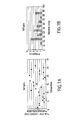
- Figure 4A gives the values of the different static moments Radials measured for each blade of these 26 games. In the example illustrated, these moments vary between 201000 and 215000 cmg. The distribution of these moments according to their values is illustrated in Figure 4B.
- Figure 5A gives the values of the different static moments tangential measured for each blade of different games. These times vary between 950 and 1850 cmg. The distribution of these moments according to their values is shown in Figure 5B.
- Figure 6A gives the values of the different axial static moments measured for each the blades of the different games. These moments vary between 4150 and 5150 cmg. The distribution of these moments according to their values is illustrated in Figure 6B.
- the radial resultant (R) + tangential (T) + axial (A) of the unbalance of the complete set of vanes (called also unbalance) is less than a fourth determined value and equal to 100cmg in this embodiment of 24 blades.
- the figure 7A gives the values of the different combined static moments (R + T + A) measured for each of the 26 games. These moments vary between 11cmg and 80cmg and so are all well below 100cmg. The distribution of these residual moments according to their values is shown in Figure 7B. We note that if the imbalance had deviated from this limit value authorized, it would have been necessary to resort to permutations or pair changes to find a value more compatible with the requested limit.
- the distribution of the 26 sets of 24 blades has been made on the basis of static moments 3D, but of course, a degraded mode on the bases only two static moments radial and tangential is also possible.
- the unbalance check result will be performed on the basis of the only radial resultant and tangential (R + T) of the static moment.
- the process of the invention exposed for a set of 24 blades is well heard applicable to any number of vanes forming a sub set of blades regularly distributed on the circumference of a rotor turbomachine.
Landscapes
- Engineering & Computer Science (AREA)
- Mechanical Engineering (AREA)
- General Engineering & Computer Science (AREA)
- Structures Of Non-Positive Displacement Pumps (AREA)
- Turbine Rotor Nozzle Sealing (AREA)
Abstract
Description
- la figure 1 montre un rotor de turbomachine muni d'aubes,
- la figure 2 est une vue de détail d'une aube particulière du rotor de la figure 1,
- la figure 3 est une vue schématique d'une machine de mesure du moment statique radial de l'aube de la figure 2, et
- les figures 4A à 7B montrent des exemples de diagrammes de répartition des moments statiques des aubes du rotor de la figure 1.
| N° Paire d'aubes | Ecart MS radial | Ecart MS axial | Ecart MS tangentiel |
| 1 (aubes 1 et 13) | 20 | 100 | 70 |
| 2 (aubes 2 et 14) | 60 | 120 | 110 |
| 3 (aubes 3 et 15) | 100 | 270 | 280 |
| 4 (aubes 4 et 16) | 20 | 250 | 140 |
| 5 (aubes 5 et 17) | 30 | 170 | 220 |
| 6 (aubes 6 et 18) | 60 | 80 | 60 |
| 7 (aubes 7 et 19) | 30 | 0 | 140 |
| 8 (aubes 8 et 20) | 50 | 210 | 260 |
| 9 (aubes 9 et 21) | 80 | 100 | 30 |
| 10 (aubes 10 et 22) | 140 | 150 | 110 |
| 11 (aubes 11 et 23) | 60 | 170 | 40 |
| 12 (aubes 12 et 24) | 60 | 160 | 240 |
Claims (10)
- Procédé de répartition des aubes d'un rotor de turbomachine dans lequel il est procédé tout d'abord à la mesure des moments statiques radial et tangentiel d'une pluralité d'aubes destinées à former ce rotor, puis ces aubes sont classées par paires selon un critère de choix déterminé dépendant de ces deux moments statiques préalablement mesurés, et enfin les aubes des paires choisies sont montées une à une sur le rotor en position diamétralement opposée.
- Procédé de répartition des aubes d'un rotor de turbomachine selon la revendication 1, caractérisé en ce que ledit critère de choix consiste à déterminer entre deux aubes données à la fois un écart de moment statique radial et un écart de moment statique tangentiel et à vérifier que ces deux écarts ne sont pas supérieurs respectivement à une première valeur déterminée et à une deuxième valeur déterminée.
- Procédé de répartition des aubes d'un rotor de turbomachine selon la revendication 2, caractérisé en ce que ladite première valeur déterminée est de 2.10-4mkg.
- Procédé de répartition des aubes d'un rotor de turbomachine selon la revendication 2, caractérisé en ce que ladite deuxième valeur déterminée est de 4.10-4mkg.
- Procédé de répartition des aubes d'un rotor de turbomachine selon la revendication 1, caractérisé en ce qu'il est en outre procédé à la mesure du moment statique axial de ladite pluralité d'aubes et le classement par paires est effectué en prenant en compte le moment statique axial ainsi mesuré.
- Procédé de répartition des aubes d'un rotor de turbomachine selon la revendication 5 et la revendication 2, caractérisé en ce que ledit critère de choix consiste à déterminer un écart de moment statique axial entre lesdites deux aubes et à vérifier qu'il n'est pas supérieur à une troisième valeur déterminée.
- Procédé de répartition des aubes d'un rotor de turbomachine selon la revendication 6, caractérisé en ce que ladite troisième valeur déterminée est de 4.10-4mkg.
- Procédé de répartition des aubes d'un rotor de turbomachine selon la revendication 5, caractérisé en ce qu'il est en outre procédé au calcul du moment statique combiné de ladite pluralité d'aubes et le classement par paires est effectué en prenant en compte le moment statique combiné ainsi calculé.
- Procédé de répartition des aubes d'un rotor de turbomachine selon la revendication 8, caractérisé en ce que ledit critère de choix consiste à déterminer un balourd des moments résiduels statiques radial, tangentiel et axial de ladite pluralité d'aubes et à vérifier qu'il n'est pas supérieur à une quatrième valeur déterminée.
- Procédé de répartition des aubes d'un rotor de turbomachine selon la revendication 9, caractérisé en ce que ladite quatrième valeur déterminée est de 1.10-4mkg.
Applications Claiming Priority (2)
| Application Number | Priority Date | Filing Date | Title |
|---|---|---|---|
| FR0209027A FR2842571B1 (fr) | 2002-07-17 | 2002-07-17 | Procede de repartition d'aubes de rotor de turbomachine |
| FR0209027 | 2002-07-17 |
Publications (2)
| Publication Number | Publication Date |
|---|---|
| EP1382858A1 true EP1382858A1 (fr) | 2004-01-21 |
| EP1382858B1 EP1382858B1 (fr) | 2008-01-09 |
Family
ID=29763897
Family Applications (1)
| Application Number | Title | Priority Date | Filing Date |
|---|---|---|---|
| EP03291757A Expired - Lifetime EP1382858B1 (fr) | 2002-07-17 | 2003-07-16 | Procédé de répartition d'aubes de rotor de turbomachine |
Country Status (8)
| Country | Link |
|---|---|
| US (1) | US7051436B2 (fr) |
| EP (1) | EP1382858B1 (fr) |
| CA (1) | CA2434487C (fr) |
| DE (1) | DE60318525T2 (fr) |
| ES (1) | ES2299674T3 (fr) |
| FR (1) | FR2842571B1 (fr) |
| RU (1) | RU2319841C2 (fr) |
| UA (1) | UA80249C2 (fr) |
Cited By (8)
| Publication number | Priority date | Publication date | Assignee | Title |
|---|---|---|---|---|
| EP1467063A1 (fr) * | 2003-04-08 | 2004-10-13 | General Electric Company | Procédé et dispositif pour assembler des machines rotatifs |
| FR2873156A1 (fr) * | 2004-07-13 | 2006-01-20 | Gen Electric | Procedes et appareils pour l'assemblage de machines tournantes |
| US8180596B2 (en) | 2004-07-13 | 2012-05-15 | General Electric Company | Methods and apparatus for assembling rotatable machines |
| FR3037168A1 (fr) * | 2015-06-08 | 2016-12-09 | Snecma | Procede de simulation de repartition d'aubes sur un disque de turbomachine |
| FR3037111A1 (fr) * | 2015-06-08 | 2016-12-09 | Snecma | Procede de fabrication d'une soufflante de turbomachine ayant un niveau de bruit reduit a des frequences multiples de rotation de ladite turbomachine |
| EP3572620A1 (fr) * | 2018-05-25 | 2019-11-27 | Rolls-Royce plc | Agencement de pale de rotor |
| EP3572619A1 (fr) * | 2018-05-25 | 2019-11-27 | Rolls-Royce plc | Agencement de pale de rotor |
| US11111816B2 (en) | 2018-05-25 | 2021-09-07 | Rolls-Royce Plc | Rotor blade arrangement |
Families Citing this family (10)
| Publication number | Priority date | Publication date | Assignee | Title |
|---|---|---|---|---|
| US7287958B2 (en) * | 2005-01-10 | 2007-10-30 | General Electric Company | Methods and apparatus for assembling rotatable machines |
| US7572101B2 (en) * | 2005-02-22 | 2009-08-11 | General Electric Company | Methods and apparatus for assembling rotatable machines |
| RU2317418C1 (ru) * | 2006-04-05 | 2008-02-20 | Открытое акционерное общество "Научно-производственное объединение "Сатурн" | Способ расстановки лопаток ротора турбомашины |
| US7497662B2 (en) * | 2006-07-31 | 2009-03-03 | General Electric Company | Methods and systems for assembling rotatable machines |
| RU2397330C2 (ru) * | 2008-09-04 | 2010-08-20 | Открытое акционерное общество "Пермский моторный завод" | Способ расстановки сопловых лопаток газотурбинного двигателя |
| GB201009216D0 (en) * | 2010-06-02 | 2010-07-21 | Rolls Royce Plc | Rotationally balancing a rotating part |
| US9862029B2 (en) | 2013-03-15 | 2018-01-09 | Kennametal Inc | Methods of making metal matrix composite and alloy articles |
| US10816429B2 (en) * | 2018-12-07 | 2020-10-27 | Raytheon Technologies Corporation | Determining a moment weight of a component based on measured surface geometry/solid model of the component |
| CN109823568B (zh) * | 2019-02-01 | 2022-06-03 | 南京乾利合科技有限责任公司 | 一种飞机桨叶力矩自动测量系统 |
| CN114812938B (zh) * | 2022-04-28 | 2025-09-26 | 中国航发南方工业有限公司 | 涡轮转子总装动平衡间接测量方法 |
Citations (2)
| Publication number | Priority date | Publication date | Assignee | Title |
|---|---|---|---|---|
| US4767272A (en) * | 1987-10-14 | 1988-08-30 | United Technologies Corporation | Method for reducing blade tip variation of a bladed rotor |
| GB2245661A (en) * | 1990-07-03 | 1992-01-08 | Rolls Royce Plc | Turbine balancing system |
Family Cites Families (5)
| Publication number | Priority date | Publication date | Assignee | Title |
|---|---|---|---|---|
| SU107708A1 (ru) * | 1956-07-18 | 1956-11-30 | В.С. Осадченко | Способ динамического уравновешивани роторов турбомашин со сменными лопатками |
| SU858429A1 (ru) * | 1980-04-25 | 1996-02-27 | Ю.И. Воронин | Способ балансировки рабочего колеса турбомашины |
| SU1157375A1 (en) * | 1983-12-06 | 1985-05-23 | Evgenij G Golmakov | Method of balancing adjustable-pitch propeller |
| SU1239535A1 (ru) * | 1984-12-11 | 1986-06-23 | Предприятие П/Я Ж-1287 | Способ сборки воздушных винтов с податливыми лопаст ми |
| GB2185116A (en) * | 1986-01-07 | 1987-07-08 | Rolls Royce | Moment weighing apparatus and method of moment weighing a member |
-
2002
- 2002-07-17 FR FR0209027A patent/FR2842571B1/fr not_active Expired - Fee Related
-
2003
- 2003-07-07 US US10/612,932 patent/US7051436B2/en not_active Expired - Lifetime
- 2003-07-08 CA CA2434487A patent/CA2434487C/fr not_active Expired - Lifetime
- 2003-07-15 RU RU2003122557/06A patent/RU2319841C2/ru active
- 2003-07-15 UA UA2003076687A patent/UA80249C2/uk unknown
- 2003-07-16 ES ES03291757T patent/ES2299674T3/es not_active Expired - Lifetime
- 2003-07-16 DE DE60318525T patent/DE60318525T2/de not_active Expired - Lifetime
- 2003-07-16 EP EP03291757A patent/EP1382858B1/fr not_active Expired - Lifetime
Patent Citations (2)
| Publication number | Priority date | Publication date | Assignee | Title |
|---|---|---|---|---|
| US4767272A (en) * | 1987-10-14 | 1988-08-30 | United Technologies Corporation | Method for reducing blade tip variation of a bladed rotor |
| GB2245661A (en) * | 1990-07-03 | 1992-01-08 | Rolls Royce Plc | Turbine balancing system |
Cited By (13)
| Publication number | Priority date | Publication date | Assignee | Title |
|---|---|---|---|---|
| EP1467063A1 (fr) * | 2003-04-08 | 2004-10-13 | General Electric Company | Procédé et dispositif pour assembler des machines rotatifs |
| US6908285B2 (en) | 2003-04-08 | 2005-06-21 | General Electric Company | Methods and apparatus for assembling rotatable machines |
| FR2873156A1 (fr) * | 2004-07-13 | 2006-01-20 | Gen Electric | Procedes et appareils pour l'assemblage de machines tournantes |
| US8180596B2 (en) | 2004-07-13 | 2012-05-15 | General Electric Company | Methods and apparatus for assembling rotatable machines |
| WO2016198790A1 (fr) * | 2015-06-08 | 2016-12-15 | Safran Aircraft Engines | Procédé de fabrication d'une soufflante de turbomachine ayant un niveau de bruit réduit a des fréquences multiples de rotation de ladite turbomachine |
| FR3037111A1 (fr) * | 2015-06-08 | 2016-12-09 | Snecma | Procede de fabrication d'une soufflante de turbomachine ayant un niveau de bruit reduit a des frequences multiples de rotation de ladite turbomachine |
| FR3037168A1 (fr) * | 2015-06-08 | 2016-12-09 | Snecma | Procede de simulation de repartition d'aubes sur un disque de turbomachine |
| US10865645B2 (en) | 2015-06-08 | 2020-12-15 | Safran Aircraft Engines | Method for manufacturing a turbomachine fan having a reduced noise level at multiple rotational frequencies of said turbomachine |
| EP3572620A1 (fr) * | 2018-05-25 | 2019-11-27 | Rolls-Royce plc | Agencement de pale de rotor |
| EP3572619A1 (fr) * | 2018-05-25 | 2019-11-27 | Rolls-Royce plc | Agencement de pale de rotor |
| US10954794B2 (en) | 2018-05-25 | 2021-03-23 | Rolls-Royce Plc | Rotor blade arrangement |
| US10989227B2 (en) | 2018-05-25 | 2021-04-27 | Rolls-Royce Plc | Rotor blade arrangement |
| US11111816B2 (en) | 2018-05-25 | 2021-09-07 | Rolls-Royce Plc | Rotor blade arrangement |
Also Published As
| Publication number | Publication date |
|---|---|
| DE60318525T2 (de) | 2009-01-08 |
| RU2319841C2 (ru) | 2008-03-20 |
| UA80249C2 (uk) | 2007-09-10 |
| CA2434487A1 (fr) | 2004-01-17 |
| EP1382858B1 (fr) | 2008-01-09 |
| US7051436B2 (en) | 2006-05-30 |
| ES2299674T3 (es) | 2008-06-01 |
| RU2003122557A (ru) | 2005-01-10 |
| CA2434487C (fr) | 2012-02-07 |
| DE60318525D1 (de) | 2008-02-21 |
| US20040013523A1 (en) | 2004-01-22 |
| FR2842571B1 (fr) | 2004-10-15 |
| FR2842571A1 (fr) | 2004-01-23 |
Similar Documents
| Publication | Publication Date | Title |
|---|---|---|
| EP1382858B1 (fr) | Procédé de répartition d'aubes de rotor de turbomachine | |
| EP2507598B1 (fr) | Procédé et dispositif de surveillance de vibrations en torsion d'un arbre rotatif d'une turbomachine | |
| FR3077638A1 (fr) | Procédé pour mesurer le balourd de rotors à arbre élastique au moyen de capteurs de déplacement | |
| CA2553880C (fr) | Controle des aubes de turbomachine | |
| EP1950379B1 (fr) | Procédé d'équilibrage modulaire de rotor de turbomachine | |
| EP1205749A1 (fr) | Contrôle acoustique de roues aubagées monoblocs | |
| EP1862698B1 (fr) | Correction du balourd d'un rotor | |
| FR2986864A1 (fr) | Methode de mesure de la deformation d'une aube de turbomachine au cours du fonctionnement de la turbomachine | |
| RU2759651C1 (ru) | Способ и устройство для балансировки ротора | |
| WO2020249686A1 (fr) | Dispositif d'équilibrage dynamique pour rotor | |
| FR3021066A1 (fr) | Disque de rotor equilibre, et procede d'equilibrage | |
| US11060941B2 (en) | Method for determining an unbalance of a shaft-elastic rotor with reference to the outward deflection | |
| WO2021094700A1 (fr) | Ensemble modulaire et autonome de detection de la position angulaire des aubes d'une roue a aubes et ensemble modulaire et autonome de detection d'endommagement des aubes d'une roue a aubes d'une turbomachine | |
| CA2716227C (fr) | Procede pour tester un revetement de pied d'aube | |
| CN112105799A (zh) | 转子平衡方法和装置 | |
| CN115541116B (zh) | 一种减小涡轮转子旋转惯性激励的控制方法 | |
| EP3578929A1 (fr) | Procédé et système de détection de la position angulaire des aubes d'une roue à aubes d'une turbomachine | |
| FR2766988A1 (fr) | Dispositif et procede d'equilibrage d'un rotor de machine tournante rapide | |
| FR2626370A1 (fr) | Procede d'equilibrage d'un rotor monte sur paliers, notamment pour turbomachine | |
| EP4542002A2 (fr) | Procédé de fabrication d'une pale de rotor avec des données de poids de moment | |
| FR3037111A1 (fr) | Procede de fabrication d'une soufflante de turbomachine ayant un niveau de bruit reduit a des frequences multiples de rotation de ladite turbomachine | |
| Regener et al. | Balancing flexible rotors of large electrical machines | |
| FR2979682A1 (fr) | Procede d'assemblage d'un groupe moto-ventilateur et dispositif de controle d'assemblage correspondant | |
| FR3108048A1 (fr) | Procede et dispositif d’equilibrage de piece de turbomachine | |
| FR3057953A1 (fr) | Procede et banc d'equilibrage d'une piece annulaire |
Legal Events
| Date | Code | Title | Description |
|---|---|---|---|
| PUAI | Public reference made under article 153(3) epc to a published international application that has entered the european phase |
Free format text: ORIGINAL CODE: 0009012 |
|
| 17P | Request for examination filed |
Effective date: 20030719 |
|
| AK | Designated contracting states |
Kind code of ref document: A1 Designated state(s): AT BE BG CH CY CZ DE DK EE ES FI FR GB GR HU IE IT LI LU MC NL PT RO SE SI SK TR |
|
| AX | Request for extension of the european patent |
Extension state: AL LT LV MK |
|
| RIN1 | Information on inventor provided before grant (corrected) |
Inventor name: TRANCHIER, JEAN-LOUIS Inventor name: BERGER, DANIEL |
|
| AKX | Designation fees paid |
Designated state(s): DE ES FR GB IT |
|
| RAP1 | Party data changed (applicant data changed or rights of an application transferred) |
Owner name: SNECMA |
|
| GRAP | Despatch of communication of intention to grant a patent |
Free format text: ORIGINAL CODE: EPIDOSNIGR1 |
|
| GRAS | Grant fee paid |
Free format text: ORIGINAL CODE: EPIDOSNIGR3 |
|
| GRAA | (expected) grant |
Free format text: ORIGINAL CODE: 0009210 |
|
| AK | Designated contracting states |
Kind code of ref document: B1 Designated state(s): DE ES FR GB IT |
|
| REG | Reference to a national code |
Ref country code: GB Ref legal event code: FG4D Free format text: NOT ENGLISH |
|
| REF | Corresponds to: |
Ref document number: 60318525 Country of ref document: DE Date of ref document: 20080221 Kind code of ref document: P |
|
| GBT | Gb: translation of ep patent filed (gb section 77(6)(a)/1977) |
Effective date: 20080408 |
|
| REG | Reference to a national code |
Ref country code: ES Ref legal event code: FG2A Ref document number: 2299674 Country of ref document: ES Kind code of ref document: T3 |
|
| PLBE | No opposition filed within time limit |
Free format text: ORIGINAL CODE: 0009261 |
|
| STAA | Information on the status of an ep patent application or granted ep patent |
Free format text: STATUS: NO OPPOSITION FILED WITHIN TIME LIMIT |
|
| 26N | No opposition filed |
Effective date: 20081010 |
|
| PGFP | Annual fee paid to national office [announced via postgrant information from national office to epo] |
Ref country code: ES Payment date: 20120716 Year of fee payment: 10 |
|
| REG | Reference to a national code |
Ref country code: ES Ref legal event code: FD2A Effective date: 20140807 |
|
| PG25 | Lapsed in a contracting state [announced via postgrant information from national office to epo] |
Ref country code: ES Free format text: LAPSE BECAUSE OF NON-PAYMENT OF DUE FEES Effective date: 20130717 |
|
| REG | Reference to a national code |
Ref country code: FR Ref legal event code: PLFP Year of fee payment: 14 |
|
| REG | Reference to a national code |
Ref country code: FR Ref legal event code: PLFP Year of fee payment: 15 |
|
| REG | Reference to a national code |
Ref country code: FR Ref legal event code: CD Owner name: SAFRAN AIRCRAFT ENGINES Effective date: 20170717 |
|
| REG | Reference to a national code |
Ref country code: FR Ref legal event code: CD Owner name: SAFRAN AIRCRAFT ENGINES, FR Effective date: 20170717 |
|
| REG | Reference to a national code |
Ref country code: FR Ref legal event code: PLFP Year of fee payment: 16 |
|
| PGFP | Annual fee paid to national office [announced via postgrant information from national office to epo] |
Ref country code: IT Payment date: 20220621 Year of fee payment: 20 Ref country code: GB Payment date: 20220621 Year of fee payment: 20 |
|
| PGFP | Annual fee paid to national office [announced via postgrant information from national office to epo] |
Ref country code: FR Payment date: 20220622 Year of fee payment: 20 |
|
| PGFP | Annual fee paid to national office [announced via postgrant information from national office to epo] |
Ref country code: DE Payment date: 20220621 Year of fee payment: 20 |
|
| REG | Reference to a national code |
Ref country code: DE Ref legal event code: R082 Ref document number: 60318525 Country of ref document: DE Representative=s name: CBDL PATENTANWAELTE GBR, DE |
|
| REG | Reference to a national code |
Ref country code: DE Ref legal event code: R071 Ref document number: 60318525 Country of ref document: DE |
|
| REG | Reference to a national code |
Ref country code: GB Ref legal event code: PE20 Expiry date: 20230715 |
|
| PG25 | Lapsed in a contracting state [announced via postgrant information from national office to epo] |
Ref country code: GB Free format text: LAPSE BECAUSE OF EXPIRATION OF PROTECTION Effective date: 20230715 |