EP1382748A2 - Leitplankenendbereich - Google Patents
Leitplankenendbereich Download PDFInfo
- Publication number
- EP1382748A2 EP1382748A2 EP03014104A EP03014104A EP1382748A2 EP 1382748 A2 EP1382748 A2 EP 1382748A2 EP 03014104 A EP03014104 A EP 03014104A EP 03014104 A EP03014104 A EP 03014104A EP 1382748 A2 EP1382748 A2 EP 1382748A2
- Authority
- EP
- European Patent Office
- Prior art keywords
- retaining member
- transverse horizontal
- horizontal retaining
- guardrail
- terminal
- Prior art date
- Legal status (The legal status is an assumption and is not a legal conclusion. Google has not performed a legal analysis and makes no representation as to the accuracy of the status listed.)
- Granted
Links
Images
Classifications
-
- E—FIXED CONSTRUCTIONS
- E01—CONSTRUCTION OF ROADS, RAILWAYS, OR BRIDGES
- E01F—ADDITIONAL WORK, SUCH AS EQUIPPING ROADS OR THE CONSTRUCTION OF PLATFORMS, HELICOPTER LANDING STAGES, SIGNS, SNOW FENCES, OR THE LIKE
- E01F15/00—Safety arrangements for slowing, redirecting or stopping errant vehicles, e.g. guard posts or bollards; Arrangements for reducing damage to roadside structures due to vehicular impact
- E01F15/14—Safety arrangements for slowing, redirecting or stopping errant vehicles, e.g. guard posts or bollards; Arrangements for reducing damage to roadside structures due to vehicular impact specially adapted for local protection, e.g. for bridge piers, for traffic islands
- E01F15/143—Protecting devices located at the ends of barriers
Definitions
- the present invention relates to a guardrail terminal.
- the present invention relates to a metal-guardrail terminal, to which the following description refers purely by way of example.
- metal guardrails normally comprise a number of vertical supporting posts fixed into the ground one after the other along the edge of a road; and a number of transverse horizontal retaining members fixed to the vertical supporting posts one after the other to form a straight longitudinal retaining strip extending continuously along the edge of the road at a given height off the ground.
- the start end of the guardrail is normally covered with safety structures for retaining or redirecting vehicles towards the centre of the road, depending on whether the impact trajectory of the vehicle against the end of the guardrail is tangent or not to the uardrail, and with deceleration obviously below current regulation thresholds.
- Safety structures for the above purpose are normally referred to as “guardrail terminals”, and normally comprise a reinforced-concrete base at ground level; a number of vertical supporting posts arranged successively in a U on the reinforced-concrete base, starting from the end of the guardrail; a number of programmed-yield anchoring bolts for securing each vertical supporting post firmly to the reinforced-concrete base; and a number of collapsible horizontal longitudinal members fixed telescopically one after the other to the vertical supporting posts to form a collapsible, substantially horseshoe-shaped horizontal beam, i.e. U-shaped in a horizontal plane.
- guardrail terminal comprises a prismatic, triangular-based tank made of plastic material, anchored to the ground immediately upstream from the start end of the guardrail, and filled with water to absorb the impact of the vehicle.
- guardrail terminal comprises a thin metal tubular member fixed vertically and directly to the vertical supporting post at the end of the guardrail.
- the first type of guardrail terminal described above has the drawback of being extremely expensive to produce, and of failing to effectively absorb the kinetic energy of the vehicle in collisions involving a vehicle travelling on the other side of the road, i.e. when the vehicle is travelling on the opposite side of the road to the edge bounded by the guardrail, and strikes the rear of the terminal, possibly after scraping against the end/initial portion of the guardrail.
- guardrail terminals described above provide for fairly poor absorption of the kinetic energy of the vehicle, and are therefore only suitable for installation on slow roads.
- a guardrail terminal characterized by comprising a number of vertical supporting members fixed to the ground one after the other along the edge of the road; a first transverse horizontal retaining member fixed to the vertical supporting members at a given height off the ground, and positioned in the horizontal plane so as to extend gradually away from the edge of the road, as of the end of the guardrail; and a curled second transverse horizontal retaining member, which projects from the terminal end of said first transverse horizontal retaining member, curves back in the horizontal plane towards said first transverse horizontal retaining member, and is fixed by its own terminal end to the start end or to an intermediate portion of said first transverse horizontal retaining member, so as to form, together with the first transverse horizontal retaining member, a substantially tear-shaped collapsible annular member.
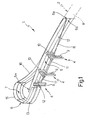
- Number 1 in the accompanying drawings indicates as a whole a guardrail terminal designed for assembly to the end of a known metal guardrail 2 extending along the edge 3 of any asphalted road or similar.
- Two specular terminals 1 may obviously also be assembled one after the other and connected to each other to form a short safety barrier surrounding small-sized obstacles, such as large trees or reinforced-concrete posts, along edge 3 of the road.
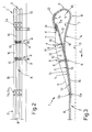
- Terminal 1 substantially comprises a number of vertical supporting members 4 fixed into the ground one after the other along edge 3 of the road; a curved first transverse horizontal retaining member 5 fixed to vertical supporting members 4 at a given height off the ground, and curving, in a horizontal plane and with a preferably, though not necessarily, constant radius of curvature, gradually away from edge 3 of the road as of the end of guardrail 2; and a curled second transverse horizontal retaining member 6, which projects from the terminal end 5a of transverse horizontal retaining member 5, curves back with a variable radius of curvature in the horizontal plane towards first transverse horizontal retaining member 5, and is fixed by its own terminal end 6a to the start end 5b or to an intermediate portion of transverse horizontal retaining member 5, so as to form, together with transverse horizontal retaining member 5, a substantially tear-shaped collapsible annular member 7.
- terminal 1 is designed for assembly to the end of guardrail 2, so that the start end 5b of transverse horizontal retaining member 5 can be fixed directly, by bolts or similar fastening systems, to the end of the last transverse horizontal retaining member 8 of guardrail 2.
- vertical supporting members 4 are three in number, and are fixed into the ground one after the other along edge 3 of the road along a curved path T, which extends gradually away from edge 3 of the road, as of the end of guardrail 2.
- the three vertical supporting members 4 are fixed into the ground and so spaced apart that a first vertical supporting member 4 supports terminal end 5a of transverse horizontal retaining member 5, while the other two vertical supporting members 4 support the central portion of transverse horizontal retaining member 5.
- the vertical supporting member 4 supporting terminal end 5a of transverse horizontal retaining member 5 is defined by a U-section metal bar 9 driven directly into the ground in a vertical position, and fixed at the top end directly to transverse horizontal retaining member 5 by bolts, rivets, or similar fastening systems.
- Each of the other two vertical supporting members 4 is defined by a U-section metal bar 9 driven directly into the ground in a vertical position, and by a collapsible spacer member 10 interposed between the top end of metal bar 9 and the body of transverse horizontal retaining member 5.
- collapsible spacer member 10 is fixed stably to transverse horizontal retaining member 5 by rivets or similar fastening systems, and is fixed to the top end of metal bar 9 by through bolts inserted inside slots formed in programmed-deformation portions of collapsible spacer member 10.
- vertical supporting members 4 are provided with a twist plate 11 connecting metal bars 9 of the three vertical supporting members 4 in known manner to one another and to the ground and/or transverse horizontal retaining members 5 and 6, to prevent the bodies of metal bars 9 from twisting, in the event of impact by a vehicle, and so impairing the ability of the bodies to discharge mechanical stress to the ground.
- curved transverse horizontal retaining member 5 is defined by a single segment 12 of corrugated sheet metal with a W-shaped cross section or three longitudinal ridges (also known as three-ridge section), which curves in the horizontal plane with a constant radius of curvature r 1 preferably, though not necessarily, ranging between 14 and 15 metres.
- a sheet metal segment 12 with a variable radius of curvature r 1 may obviously also be used.
- curled transverse horizontal retaining member 6 is defined by three segments of W- or three-ridge-section corrugated sheet metal, the first of which, hereinafter indicated 13, defines an extension of segment 12, and is bent substantially into an L in the horizontal plane, so that the central portion has a preferably, though not necessarily, constant radius of curvature r 2 ranging between 0.4 and 0.6 of a metre.
- the end of segment 13 is fixed to the end of segment 12 by a connecting member 14 for stably connecting two specularly positioned pieces of W- or three-ridge-section corrugated sheet metal.
- the second W- or three-ridge-section segment of corrugated sheet metal, hereinafter indicated 15, defines an extension of segment 13, to which it is fixed by rivets, self-locking bolts or similar fastening systems, and is bent substantially into a V in the horizontal plane, so that the central portion has a constant radius of curvature r 3 ranging between 0.4 and 0.6 of a metre.
- the third W- or three-ridge-section segment of corrugated sheet metal defines an extension of segment 15, to which it is fixed by rivets, self-locking bolts or similar fastening systems, and is bent substantially into an S in the horizontal plane, so that the first portion has a constant radius of curvature r 4 ranging between 3 and 4 metres, and the second portion has a constant radius of curvature r 5 substantially equal to radius of curvature r 1 of segment 12, so that part of the length of the second portion overlaps segment 12.
- the second end of segment 16 obviously defines terminal end 6a of transverse horizontal retaining member 6, and is fixed directly to the body of segment 12 by rivets, self-locking bolts or similar fastening systems.
- the second end of segment 16 is fixed directly onto the start end of segment 12, in turn defining the start end 5b of transverse horizontal retaining member 5.
- segment 16 may be straight, at least along the second portion, so that it only comes into direct contact with the surface of segment 12 close to the point at which it is fastened to the end of segment 12.
- corrugated sheet metal segments 13, 15 and 16 are all the same thickness, but sheet metal segments of different thicknesses may be used to maximize absorption of the kinetic energy of the vehicle as a function of the maximum deceleration to which the vehicle and occupants are subjected.
- Transverse horizontal retaining member 6 may obviously also be made of a single segment of W- or three-ridge-section corrugated sheet metal, at slightly higher production cost.
- terminal 1 Operation of terminal 1 is easily deducible from the above description and attached drawings, with no further explanation required.
- transverse horizontal retaining members 5 and 6 i.e. the tear shape of collapsible annular member 7, effectively slows down the vehicle, in the event of impact, and provides, at the initial impact stage, for maximum deceleration well below current safety regulation thresholds.
- transverse horizontal retaining member 6 At the initial impact stage, in fact, the kinetic energy of the vehicle is absorbed solely by deformation of transverse horizontal retaining member 6; transverse horizontal retaining member 5 only being involved later, when transverse horizontal retaining member 6 is fully collapsed and has transferred all the mechanical stress to transverse horizontal retaining member 5.
- transverse horizontal retaining member 5 also provides for redirecting the vehicle towards the centre of the road, even in the worst-case impact conditions, i.e. when the impact trajectory of the vehicle is parallel to the normal travelling direction d.
- guardrail terminals simply absorb all the kinetic energy of the vehicle, with considerable deceleration, given the small amount of space available.
- Terminal 1 is so structured as to combine perfectly with known metal guardrails 2, and provides for effective protection even in the event of impact by vehicles travelling on the other side of the road.
- terminal 1 provides for redirecting the vehicle towards the centre of the road, even in the worst possible conditions, and ensures, in any condition, deceleration well below current safety regulation thresholds.
- Guardrail terminal 1 as described and illustrated herein also has the big advantage of being made from elements derived from currently used metal guardrails 2, thus greatly reducing production cost as compared with known terminals.
- terminal 1 as described and illustrated herein without, however, departing from the scope of the present invention.
- transverse horizontal retaining member 5 is straight, while still defining a substantially tear-shaped collapsible annular member 7 together with transverse horizontal retaining member 6.
- transverse horizontal retaining member 5 is obviously positioned in the horizontal plane so as to extend gradually away from edge 3 of the road, as of the end of guardrail 2.
Landscapes
- Engineering & Computer Science (AREA)
- Architecture (AREA)
- Civil Engineering (AREA)
- Structural Engineering (AREA)
- Refuge Islands, Traffic Blockers, Or Guard Fence (AREA)
- Road Signs Or Road Markings (AREA)
Applications Claiming Priority (2)
| Application Number | Priority Date | Filing Date | Title |
|---|---|---|---|
| ITTO20020620 | 2002-07-16 | ||
| IT2002TO000620A ITTO20020620A1 (it) | 2002-07-16 | 2002-07-16 | Terminale di barriera stradale |
Publications (3)
| Publication Number | Publication Date |
|---|---|
| EP1382748A2 true EP1382748A2 (de) | 2004-01-21 |
| EP1382748A3 EP1382748A3 (de) | 2004-05-12 |
| EP1382748B1 EP1382748B1 (de) | 2007-04-18 |
Family
ID=11459501
Family Applications (1)
| Application Number | Title | Priority Date | Filing Date |
|---|---|---|---|
| EP03014104A Expired - Lifetime EP1382748B1 (de) | 2002-07-16 | 2003-06-23 | Leitplankenendbereich |
Country Status (6)
| Country | Link |
|---|---|
| US (1) | US6948880B2 (de) |
| EP (1) | EP1382748B1 (de) |
| AT (1) | ATE360118T1 (de) |
| DE (1) | DE60313253D1 (de) |
| IT (1) | ITTO20020620A1 (de) |
| RU (1) | RU2307210C2 (de) |
Cited By (5)
| Publication number | Priority date | Publication date | Assignee | Title |
|---|---|---|---|---|
| US6948880B2 (en) * | 2002-07-16 | 2005-09-27 | Metalmeccanica Fracasso S.P.A. | Guardrail terminal |
| FR2876715A1 (fr) * | 2004-10-19 | 2006-04-21 | Profiles Du Ct Sa | Embout de protection pour ecran de glissiere de securite routiere |
| WO2007144141A1 (en) * | 2006-06-13 | 2007-12-21 | Corus Uk Limited | Vehicle safety barriers |
| WO2007144656A1 (en) * | 2006-06-13 | 2007-12-21 | Corus Uk Limited | Vehicle safety barriers |
| WO2020081683A1 (en) * | 2018-10-16 | 2020-04-23 | The Texas A&M University System | Deflector bracket and cable anchor for guardrail terminal |
Families Citing this family (2)
| Publication number | Priority date | Publication date | Assignee | Title |
|---|---|---|---|---|
| SE535428C2 (sv) * | 2010-12-02 | 2012-08-07 | Birstaverken Ab | Påkörningsskydd för fordon innefattande en energiabsorberande anordning |
| RU2593268C1 (ru) * | 2015-04-10 | 2016-08-10 | Андрей Александрович Щербина | Барьерное ограждение для автодорог и мостовых переходов |
Family Cites Families (12)
| Publication number | Priority date | Publication date | Assignee | Title |
|---|---|---|---|---|
| US2154818A (en) * | 1936-07-17 | 1939-04-18 | Eimco Corp | Flexible highway guard |
| US2091925A (en) * | 1936-11-28 | 1937-08-31 | Francis O Heltzel | Guardrail |
| US2776116A (en) * | 1953-10-29 | 1957-01-01 | Acme Highway Prod | Beam guard for highways and the like |
| US4330106A (en) * | 1979-05-02 | 1982-05-18 | Chisholm Douglas B | Guard rail construction |
| US4607824A (en) * | 1983-01-11 | 1986-08-26 | Energy Absorption Systems, Inc. | Guardrail end terminal |
| JP3039769B2 (ja) * | 1995-12-20 | 2000-05-08 | 日鐵建材工業株式会社 | ガードレール端末部構造 |
| US5791812A (en) * | 1996-10-11 | 1998-08-11 | The Texas A&M University System | Collision performance side impact (automobile penetration guard) |
| US6024341A (en) * | 1997-05-05 | 2000-02-15 | Traffix Devices, Inc. | Crash attenuator of compressible sections |
| US5967497A (en) * | 1997-12-15 | 1999-10-19 | Energy Absorption Systems, Inc. | Highway barrier and guardrail |
| US6575434B2 (en) * | 1999-12-17 | 2003-06-10 | The Texas A&M University System | Apparatus and methods for strengthening guardrail installations |
| DE10116701A1 (de) * | 2000-09-12 | 2002-03-28 | Outimex Bautechnik Gmbh | Leitelement für Schutzeinrichtungen |
| ITTO20020620A1 (it) * | 2002-07-16 | 2004-01-16 | Fracasso Metalmeccanica | Terminale di barriera stradale |
-
2002
- 2002-07-16 IT IT2002TO000620A patent/ITTO20020620A1/it unknown
-
2003
- 2003-04-07 RU RU2003109940/03A patent/RU2307210C2/ru not_active IP Right Cessation
- 2003-06-20 US US10/601,053 patent/US6948880B2/en not_active Expired - Fee Related
- 2003-06-23 AT AT03014104T patent/ATE360118T1/de not_active IP Right Cessation
- 2003-06-23 DE DE60313253T patent/DE60313253D1/de not_active Expired - Lifetime
- 2003-06-23 EP EP03014104A patent/EP1382748B1/de not_active Expired - Lifetime
Cited By (7)
| Publication number | Priority date | Publication date | Assignee | Title |
|---|---|---|---|---|
| US6948880B2 (en) * | 2002-07-16 | 2005-09-27 | Metalmeccanica Fracasso S.P.A. | Guardrail terminal |
| FR2876715A1 (fr) * | 2004-10-19 | 2006-04-21 | Profiles Du Ct Sa | Embout de protection pour ecran de glissiere de securite routiere |
| EP1650354A1 (de) * | 2004-10-19 | 2006-04-26 | Les Profiles Du Centre | Schutzkappe für einen Strassenleitplanke |
| WO2007144141A1 (en) * | 2006-06-13 | 2007-12-21 | Corus Uk Limited | Vehicle safety barriers |
| WO2007144656A1 (en) * | 2006-06-13 | 2007-12-21 | Corus Uk Limited | Vehicle safety barriers |
| WO2020081683A1 (en) * | 2018-10-16 | 2020-04-23 | The Texas A&M University System | Deflector bracket and cable anchor for guardrail terminal |
| US11326314B2 (en) | 2018-10-16 | 2022-05-10 | The Texas A&M University System | Deflector bracket and cable anchor for guardrail terminal |
Also Published As
| Publication number | Publication date |
|---|---|
| EP1382748B1 (de) | 2007-04-18 |
| ITTO20020620A0 (it) | 2002-07-16 |
| DE60313253D1 (de) | 2007-05-31 |
| EP1382748A3 (de) | 2004-05-12 |
| US20040062603A1 (en) | 2004-04-01 |
| US6948880B2 (en) | 2005-09-27 |
| ITTO20020620A1 (it) | 2004-01-16 |
| ATE360118T1 (de) | 2007-05-15 |
| RU2307210C2 (ru) | 2007-09-27 |
Similar Documents
| Publication | Publication Date | Title |
|---|---|---|
| US6644888B2 (en) | Roadway guardrail structure | |
| AU742837B2 (en) | Highway barrier and guardrail | |
| US6173943B1 (en) | Guardrail with slidable impact-receiving element | |
| US5078366A (en) | Guardrail extruder terminal | |
| US6554256B2 (en) | Highway guardrail end terminal assembly | |
| US6719483B1 (en) | Collision safety device | |
| US6290427B1 (en) | Guardrail beam with enhanced stability | |
| EP1026326A1 (de) | Verbesserter Leitplanken-Endbereich zum schrittweisen Absorbieren der Aufprallenergie | |
| EP0398923A1 (de) | Leitplankenextruderende. | |
| GB2406127A (en) | Road safety barriers | |
| WO1997025482A1 (en) | Guardrail system | |
| EP1382748B1 (de) | Leitplankenendbereich | |
| US6234437B1 (en) | Flexible support | |
| EP3277885B1 (de) | Schutzplanke mit abstandhalter | |
| US4289301A (en) | Post for a guard rail | |
| KR101083269B1 (ko) | 차량 방호 울타리 | |
| JP2005188031A (ja) | 防護柵用支柱 | |
| EP1612334A1 (de) | Strassenleitplanke | |
| EP3277886B1 (de) | Abstandhalter für schutzplanke | |
| EP1612333A1 (de) | Pfosten | |
| US20040114996A1 (en) | Front impact damper | |
| JP4817950B2 (ja) | コンクリート擁壁と防護柵と車輪誘導柵の複合施設 | |
| JP2011190679A (ja) | コンクリート擁壁と防護柵と車輪誘導柵の複合施設 | |
| AU2022419531A1 (en) | Flexible tensioned crash barrier | |
| EP2746461B1 (de) | Leitplankenträger |
Legal Events
| Date | Code | Title | Description |
|---|---|---|---|
| PUAI | Public reference made under article 153(3) epc to a published international application that has entered the european phase |
Free format text: ORIGINAL CODE: 0009012 |
|
| AK | Designated contracting states |
Kind code of ref document: A2 Designated state(s): AT BE BG CH CY CZ DE DK EE ES FI FR GB GR HU IE IT LI LU MC NL PT RO SE SI SK TR |
|
| AX | Request for extension of the european patent |
Extension state: AL LT LV MK |
|
| PUAL | Search report despatched |
Free format text: ORIGINAL CODE: 0009013 |
|
| AK | Designated contracting states |
Kind code of ref document: A3 Designated state(s): AT BE BG CH CY CZ DE DK EE ES FI FR GB GR HU IE IT LI LU MC NL PT RO SE SI SK TR |
|
| AX | Request for extension of the european patent |
Extension state: AL LT LV MK |
|
| 17P | Request for examination filed |
Effective date: 20041111 |
|
| AKX | Designation fees paid |
Designated state(s): AT BE BG CH CY CZ DE DK EE ES FI FR GB GR HU IE IT LI LU MC NL PT RO SE SI SK TR |
|
| TPAC | Observations filed by third parties |
Free format text: ORIGINAL CODE: EPIDOSNTIPA |
|
| GRAP | Despatch of communication of intention to grant a patent |
Free format text: ORIGINAL CODE: EPIDOSNIGR1 |
|
| GRAS | Grant fee paid |
Free format text: ORIGINAL CODE: EPIDOSNIGR3 |
|
| GRAA | (expected) grant |
Free format text: ORIGINAL CODE: 0009210 |
|
| AK | Designated contracting states |
Kind code of ref document: B1 Designated state(s): AT BE BG CH CY CZ DE DK EE ES FI FR GB GR HU IE IT LI LU MC NL PT RO SE SI SK TR |
|
| PG25 | Lapsed in a contracting state [announced via postgrant information from national office to epo] |
Ref country code: LI Free format text: LAPSE BECAUSE OF FAILURE TO SUBMIT A TRANSLATION OF THE DESCRIPTION OR TO PAY THE FEE WITHIN THE PRESCRIBED TIME-LIMIT Effective date: 20070418 Ref country code: SI Free format text: LAPSE BECAUSE OF FAILURE TO SUBMIT A TRANSLATION OF THE DESCRIPTION OR TO PAY THE FEE WITHIN THE PRESCRIBED TIME-LIMIT Effective date: 20070418 Ref country code: FI Free format text: LAPSE BECAUSE OF FAILURE TO SUBMIT A TRANSLATION OF THE DESCRIPTION OR TO PAY THE FEE WITHIN THE PRESCRIBED TIME-LIMIT Effective date: 20070418 Ref country code: CH Free format text: LAPSE BECAUSE OF FAILURE TO SUBMIT A TRANSLATION OF THE DESCRIPTION OR TO PAY THE FEE WITHIN THE PRESCRIBED TIME-LIMIT Effective date: 20070418 |
|
| REG | Reference to a national code |
Ref country code: CH Ref legal event code: EP |
|
| REG | Reference to a national code |
Ref country code: IE Ref legal event code: FG4D |
|
| REF | Corresponds to: |
Ref document number: 60313253 Country of ref document: DE Date of ref document: 20070531 Kind code of ref document: P |
|
| PG25 | Lapsed in a contracting state [announced via postgrant information from national office to epo] |
Ref country code: SE Free format text: LAPSE BECAUSE OF FAILURE TO SUBMIT A TRANSLATION OF THE DESCRIPTION OR TO PAY THE FEE WITHIN THE PRESCRIBED TIME-LIMIT Effective date: 20070718 |
|
| PG25 | Lapsed in a contracting state [announced via postgrant information from national office to epo] |
Ref country code: ES Free format text: LAPSE BECAUSE OF FAILURE TO SUBMIT A TRANSLATION OF THE DESCRIPTION OR TO PAY THE FEE WITHIN THE PRESCRIBED TIME-LIMIT Effective date: 20070729 |
|
| PG25 | Lapsed in a contracting state [announced via postgrant information from national office to epo] |
Ref country code: PT Free format text: LAPSE BECAUSE OF FAILURE TO SUBMIT A TRANSLATION OF THE DESCRIPTION OR TO PAY THE FEE WITHIN THE PRESCRIBED TIME-LIMIT Effective date: 20070918 |
|
| REG | Reference to a national code |
Ref country code: CH Ref legal event code: PL |
|
| NLV1 | Nl: lapsed or annulled due to failure to fulfill the requirements of art. 29p and 29m of the patents act | ||
| PG25 | Lapsed in a contracting state [announced via postgrant information from national office to epo] |
Ref country code: AT Free format text: LAPSE BECAUSE OF FAILURE TO SUBMIT A TRANSLATION OF THE DESCRIPTION OR TO PAY THE FEE WITHIN THE PRESCRIBED TIME-LIMIT Effective date: 20070418 |
|
| EN | Fr: translation not filed | ||
| PG25 | Lapsed in a contracting state [announced via postgrant information from national office to epo] |
Ref country code: BE Free format text: LAPSE BECAUSE OF FAILURE TO SUBMIT A TRANSLATION OF THE DESCRIPTION OR TO PAY THE FEE WITHIN THE PRESCRIBED TIME-LIMIT Effective date: 20070418 |
|
| PG25 | Lapsed in a contracting state [announced via postgrant information from national office to epo] |
Ref country code: DK Free format text: LAPSE BECAUSE OF FAILURE TO SUBMIT A TRANSLATION OF THE DESCRIPTION OR TO PAY THE FEE WITHIN THE PRESCRIBED TIME-LIMIT Effective date: 20070418 Ref country code: BG Free format text: LAPSE BECAUSE OF FAILURE TO SUBMIT A TRANSLATION OF THE DESCRIPTION OR TO PAY THE FEE WITHIN THE PRESCRIBED TIME-LIMIT Effective date: 20070718 Ref country code: DE Free format text: LAPSE BECAUSE OF FAILURE TO SUBMIT A TRANSLATION OF THE DESCRIPTION OR TO PAY THE FEE WITHIN THE PRESCRIBED TIME-LIMIT Effective date: 20070719 Ref country code: NL Free format text: LAPSE BECAUSE OF FAILURE TO SUBMIT A TRANSLATION OF THE DESCRIPTION OR TO PAY THE FEE WITHIN THE PRESCRIBED TIME-LIMIT Effective date: 20070418 Ref country code: CZ Free format text: LAPSE BECAUSE OF FAILURE TO SUBMIT A TRANSLATION OF THE DESCRIPTION OR TO PAY THE FEE WITHIN THE PRESCRIBED TIME-LIMIT Effective date: 20070418 Ref country code: MC Free format text: LAPSE BECAUSE OF NON-PAYMENT OF DUE FEES Effective date: 20070630 |
|
| PLBE | No opposition filed within time limit |
Free format text: ORIGINAL CODE: 0009261 |
|
| STAA | Information on the status of an ep patent application or granted ep patent |
Free format text: STATUS: NO OPPOSITION FILED WITHIN TIME LIMIT |
|
| PG25 | Lapsed in a contracting state [announced via postgrant information from national office to epo] |
Ref country code: SK Free format text: LAPSE BECAUSE OF FAILURE TO SUBMIT A TRANSLATION OF THE DESCRIPTION OR TO PAY THE FEE WITHIN THE PRESCRIBED TIME-LIMIT Effective date: 20070418 |
|
| 26N | No opposition filed |
Effective date: 20080121 |
|
| GBPC | Gb: european patent ceased through non-payment of renewal fee |
Effective date: 20070718 |
|
| PG25 | Lapsed in a contracting state [announced via postgrant information from national office to epo] |
Ref country code: FR Free format text: LAPSE BECAUSE OF FAILURE TO SUBMIT A TRANSLATION OF THE DESCRIPTION OR TO PAY THE FEE WITHIN THE PRESCRIBED TIME-LIMIT Effective date: 20071214 Ref country code: GR Free format text: LAPSE BECAUSE OF FAILURE TO SUBMIT A TRANSLATION OF THE DESCRIPTION OR TO PAY THE FEE WITHIN THE PRESCRIBED TIME-LIMIT Effective date: 20070719 Ref country code: IT Free format text: LAPSE BECAUSE OF NON-PAYMENT OF DUE FEES Effective date: 20070623 |
|
| PG25 | Lapsed in a contracting state [announced via postgrant information from national office to epo] |
Ref country code: GB Free format text: LAPSE BECAUSE OF NON-PAYMENT OF DUE FEES Effective date: 20070718 Ref country code: IE Free format text: LAPSE BECAUSE OF NON-PAYMENT OF DUE FEES Effective date: 20070625 Ref country code: RO Free format text: LAPSE BECAUSE OF FAILURE TO SUBMIT A TRANSLATION OF THE DESCRIPTION OR TO PAY THE FEE WITHIN THE PRESCRIBED TIME-LIMIT Effective date: 20070418 |
|
| PG25 | Lapsed in a contracting state [announced via postgrant information from national office to epo] |
Ref country code: FR Free format text: LAPSE BECAUSE OF FAILURE TO SUBMIT A TRANSLATION OF THE DESCRIPTION OR TO PAY THE FEE WITHIN THE PRESCRIBED TIME-LIMIT Effective date: 20070418 |
|
| PGRI | Patent reinstated in contracting state [announced from national office to epo] |
Ref country code: IT Effective date: 20081001 |
|
| PG25 | Lapsed in a contracting state [announced via postgrant information from national office to epo] |
Ref country code: EE Free format text: LAPSE BECAUSE OF FAILURE TO SUBMIT A TRANSLATION OF THE DESCRIPTION OR TO PAY THE FEE WITHIN THE PRESCRIBED TIME-LIMIT Effective date: 20070418 |
|
| PG25 | Lapsed in a contracting state [announced via postgrant information from national office to epo] |
Ref country code: CY Free format text: LAPSE BECAUSE OF FAILURE TO SUBMIT A TRANSLATION OF THE DESCRIPTION OR TO PAY THE FEE WITHIN THE PRESCRIBED TIME-LIMIT Effective date: 20070418 |
|
| PG25 | Lapsed in a contracting state [announced via postgrant information from national office to epo] |
Ref country code: LU Free format text: LAPSE BECAUSE OF NON-PAYMENT OF DUE FEES Effective date: 20070623 |
|
| PGRI | Patent reinstated in contracting state [announced from national office to epo] |
Ref country code: IT Effective date: 20081001 |
|
| PG25 | Lapsed in a contracting state [announced via postgrant information from national office to epo] |
Ref country code: TR Free format text: LAPSE BECAUSE OF FAILURE TO SUBMIT A TRANSLATION OF THE DESCRIPTION OR TO PAY THE FEE WITHIN THE PRESCRIBED TIME-LIMIT Effective date: 20070418 Ref country code: HU Free format text: LAPSE BECAUSE OF FAILURE TO SUBMIT A TRANSLATION OF THE DESCRIPTION OR TO PAY THE FEE WITHIN THE PRESCRIBED TIME-LIMIT Effective date: 20071019 |
|
| PGRI | Patent reinstated in contracting state [announced from national office to epo] |
Ref country code: IT Effective date: 20110616 |
|
| PGFP | Annual fee paid to national office [announced via postgrant information from national office to epo] |
Ref country code: IT Payment date: 20120627 Year of fee payment: 10 |
|
| PG25 | Lapsed in a contracting state [announced via postgrant information from national office to epo] |
Ref country code: IT Free format text: LAPSE BECAUSE OF NON-PAYMENT OF DUE FEES Effective date: 20130623 |