EP1382441A9 - A process for the automated assembling of composite glasses and an automated apparatus therefor - Google Patents
A process for the automated assembling of composite glasses and an automated apparatus therefor Download PDFInfo
- Publication number
- EP1382441A9 EP1382441A9 EP03077198A EP03077198A EP1382441A9 EP 1382441 A9 EP1382441 A9 EP 1382441A9 EP 03077198 A EP03077198 A EP 03077198A EP 03077198 A EP03077198 A EP 03077198A EP 1382441 A9 EP1382441 A9 EP 1382441A9
- Authority
- EP
- European Patent Office
- Prior art keywords
- glass
- station
- assembling
- composite
- plastic material
- Prior art date
- Legal status (The legal status is an assumption and is not a legal conclusion. Google has not performed a legal analysis and makes no representation as to the accuracy of the status listed.)
- Withdrawn
Links
- 239000011521 glass Substances 0.000 title claims abstract description 93
- 239000002131 composite material Substances 0.000 title claims abstract description 26
- 238000000034 method Methods 0.000 title claims abstract description 17
- 238000005520 cutting process Methods 0.000 claims abstract description 13
- 239000000463 material Substances 0.000 claims abstract description 13
- 229920003023 plastic Polymers 0.000 claims abstract description 12
- 230000002093 peripheral effect Effects 0.000 claims abstract description 6
- 229920002037 poly(vinyl butyral) polymer Polymers 0.000 description 39
- 238000004519 manufacturing process Methods 0.000 description 7
- 238000005516 engineering process Methods 0.000 description 4
- 125000000391 vinyl group Chemical group [H]C([*])=C([H])[H] 0.000 description 3
- 229920002554 vinyl polymer Polymers 0.000 description 3
- 230000033001 locomotion Effects 0.000 description 2
- 229910000831 Steel Inorganic materials 0.000 description 1
- 230000001133 acceleration Effects 0.000 description 1
- 238000004378 air conditioning Methods 0.000 description 1
- 238000005452 bending Methods 0.000 description 1
- 230000003750 conditioning effect Effects 0.000 description 1
- 230000008878 coupling Effects 0.000 description 1
- 238000010168 coupling process Methods 0.000 description 1
- 238000005859 coupling reaction Methods 0.000 description 1
- 230000007613 environmental effect Effects 0.000 description 1
- 238000009434 installation Methods 0.000 description 1
- 239000010959 steel Substances 0.000 description 1
- 238000004659 sterilization and disinfection Methods 0.000 description 1
- 238000003860 storage Methods 0.000 description 1
- 230000001360 synchronised effect Effects 0.000 description 1
Images


Classifications
-
- C—CHEMISTRY; METALLURGY
- C03—GLASS; MINERAL OR SLAG WOOL
- C03B—MANUFACTURE, SHAPING, OR SUPPLEMENTARY PROCESSES
- C03B33/00—Severing cooled glass
- C03B33/07—Cutting armoured, multi-layered, coated or laminated, glass products
- C03B33/076—Laminated glass comprising interlayers
- C03B33/078—Polymeric interlayers
-
- B—PERFORMING OPERATIONS; TRANSPORTING
- B26—HAND CUTTING TOOLS; CUTTING; SEVERING
- B26D—CUTTING; DETAILS COMMON TO MACHINES FOR PERFORATING, PUNCHING, CUTTING-OUT, STAMPING-OUT OR SEVERING
- B26D3/00—Cutting work characterised by the nature of the cut made; Apparatus therefor
- B26D3/10—Making cuts of other than simple rectilinear form
-
- B—PERFORMING OPERATIONS; TRANSPORTING
- B32—LAYERED PRODUCTS
- B32B—LAYERED PRODUCTS, i.e. PRODUCTS BUILT-UP OF STRATA OF FLAT OR NON-FLAT, e.g. CELLULAR OR HONEYCOMB, FORM
- B32B17/00—Layered products essentially comprising sheet glass, or glass, slag, or like fibres
- B32B17/06—Layered products essentially comprising sheet glass, or glass, slag, or like fibres comprising glass as the main or only constituent of a layer, next to another layer of a specific material
- B32B17/10—Layered products essentially comprising sheet glass, or glass, slag, or like fibres comprising glass as the main or only constituent of a layer, next to another layer of a specific material of synthetic resin
- B32B17/10005—Layered products essentially comprising sheet glass, or glass, slag, or like fibres comprising glass as the main or only constituent of a layer, next to another layer of a specific material of synthetic resin laminated safety glass or glazing
- B32B17/10009—Layered products essentially comprising sheet glass, or glass, slag, or like fibres comprising glass as the main or only constituent of a layer, next to another layer of a specific material of synthetic resin laminated safety glass or glazing characterized by the number, the constitution or treatment of glass sheets
- B32B17/10036—Layered products essentially comprising sheet glass, or glass, slag, or like fibres comprising glass as the main or only constituent of a layer, next to another layer of a specific material of synthetic resin laminated safety glass or glazing characterized by the number, the constitution or treatment of glass sheets comprising two outer glass sheets
-
- B—PERFORMING OPERATIONS; TRANSPORTING
- B32—LAYERED PRODUCTS
- B32B—LAYERED PRODUCTS, i.e. PRODUCTS BUILT-UP OF STRATA OF FLAT OR NON-FLAT, e.g. CELLULAR OR HONEYCOMB, FORM
- B32B17/00—Layered products essentially comprising sheet glass, or glass, slag, or like fibres
- B32B17/06—Layered products essentially comprising sheet glass, or glass, slag, or like fibres comprising glass as the main or only constituent of a layer, next to another layer of a specific material
- B32B17/10—Layered products essentially comprising sheet glass, or glass, slag, or like fibres comprising glass as the main or only constituent of a layer, next to another layer of a specific material of synthetic resin
- B32B17/10005—Layered products essentially comprising sheet glass, or glass, slag, or like fibres comprising glass as the main or only constituent of a layer, next to another layer of a specific material of synthetic resin laminated safety glass or glazing
- B32B17/1055—Layered products essentially comprising sheet glass, or glass, slag, or like fibres comprising glass as the main or only constituent of a layer, next to another layer of a specific material of synthetic resin laminated safety glass or glazing characterized by the resin layer, i.e. interlayer
- B32B17/10761—Layered products essentially comprising sheet glass, or glass, slag, or like fibres comprising glass as the main or only constituent of a layer, next to another layer of a specific material of synthetic resin laminated safety glass or glazing characterized by the resin layer, i.e. interlayer containing vinyl acetal
-
- B—PERFORMING OPERATIONS; TRANSPORTING
- B32—LAYERED PRODUCTS
- B32B—LAYERED PRODUCTS, i.e. PRODUCTS BUILT-UP OF STRATA OF FLAT OR NON-FLAT, e.g. CELLULAR OR HONEYCOMB, FORM
- B32B17/00—Layered products essentially comprising sheet glass, or glass, slag, or like fibres
- B32B17/06—Layered products essentially comprising sheet glass, or glass, slag, or like fibres comprising glass as the main or only constituent of a layer, next to another layer of a specific material
- B32B17/10—Layered products essentially comprising sheet glass, or glass, slag, or like fibres comprising glass as the main or only constituent of a layer, next to another layer of a specific material of synthetic resin
- B32B17/10005—Layered products essentially comprising sheet glass, or glass, slag, or like fibres comprising glass as the main or only constituent of a layer, next to another layer of a specific material of synthetic resin laminated safety glass or glazing
- B32B17/10807—Making laminated safety glass or glazing; Apparatus therefor
- B32B17/10899—Making laminated safety glass or glazing; Apparatus therefor by introducing interlayers of synthetic resin
- B32B17/10935—Making laminated safety glass or glazing; Apparatus therefor by introducing interlayers of synthetic resin as a preformed layer, e.g. formed by extrusion
-
- B—PERFORMING OPERATIONS; TRANSPORTING
- B32—LAYERED PRODUCTS
- B32B—LAYERED PRODUCTS, i.e. PRODUCTS BUILT-UP OF STRATA OF FLAT OR NON-FLAT, e.g. CELLULAR OR HONEYCOMB, FORM
- B32B17/00—Layered products essentially comprising sheet glass, or glass, slag, or like fibres
- B32B17/06—Layered products essentially comprising sheet glass, or glass, slag, or like fibres comprising glass as the main or only constituent of a layer, next to another layer of a specific material
- B32B17/10—Layered products essentially comprising sheet glass, or glass, slag, or like fibres comprising glass as the main or only constituent of a layer, next to another layer of a specific material of synthetic resin
- B32B17/10005—Layered products essentially comprising sheet glass, or glass, slag, or like fibres comprising glass as the main or only constituent of a layer, next to another layer of a specific material of synthetic resin laminated safety glass or glazing
- B32B17/10807—Making laminated safety glass or glazing; Apparatus therefor
- B32B17/10899—Making laminated safety glass or glazing; Apparatus therefor by introducing interlayers of synthetic resin
- B32B17/10954—Making laminated safety glass or glazing; Apparatus therefor by introducing interlayers of synthetic resin by using an aligning laminating device
-
- B—PERFORMING OPERATIONS; TRANSPORTING
- B65—CONVEYING; PACKING; STORING; HANDLING THIN OR FILAMENTARY MATERIAL
- B65G—TRANSPORT OR STORAGE DEVICES, e.g. CONVEYORS FOR LOADING OR TIPPING, SHOP CONVEYOR SYSTEMS OR PNEUMATIC TUBE CONVEYORS
- B65G49/00—Conveying systems characterised by their application for specified purposes not otherwise provided for
- B65G49/05—Conveying systems characterised by their application for specified purposes not otherwise provided for for fragile or damageable materials or articles
- B65G49/06—Conveying systems characterised by their application for specified purposes not otherwise provided for for fragile or damageable materials or articles for fragile sheets, e.g. glass
- B65G49/068—Stacking or destacking devices; Means for preventing damage to stacked sheets, e.g. spaces
-
- B—PERFORMING OPERATIONS; TRANSPORTING
- B65—CONVEYING; PACKING; STORING; HANDLING THIN OR FILAMENTARY MATERIAL
- B65G—TRANSPORT OR STORAGE DEVICES, e.g. CONVEYORS FOR LOADING OR TIPPING, SHOP CONVEYOR SYSTEMS OR PNEUMATIC TUBE CONVEYORS
- B65G2249/00—Aspects relating to conveying systems for the manufacture of fragile sheets
- B65G2249/04—Arrangements of vacuum systems or suction cups
Definitions
- the present invention relates to a method and a compact sized apparatus for the assembly of composite glasses such as windshields for vehicles or the like.
- a typical automobile windshield is a composite glass pane, made up of two thin glass panes, usually called “inner glass”, intended for the interior of the automobile, and “outer glass”, joined together by means of an intermediate layer of plastic material such as Polyvinylbutyral
- a first disadvantage for the mounting of such components is linked to the type of work which is extremely challenging, because the efficiency it requires is based on critical parameters with very low tolerance and this implies vast investments for industry. Moreover, excluding just a few cases, to date there is another disadvantage associated with the process for mounting said composite glasses, given by the fact that they are to be mounted mainly by hand in production lines, entailing an excessive burden in terms of time, specialised labour and costs.
- the method and the apparatus of the present invention is aimed at solving the aforesaid drawbacks, because it was designed for the automobile glass industry, thereby providing the most advanced technology for the automated assembly of laminated windshields.
- the present invention provides a method for assembling a composite glass which is characterised in that it comprises the steps set out in the characterising part of claim 1.
- the present invention also provides an apparatus characterised by the operative stations as set out in the characterising part of claim 5.
- the related configuration of the apparatus of the present invention allows to carry out all the main steps of the assembling process, with the smallest bulk ever achieved heretofore.
- the feeding and arrangement of the "inner glass” and of the "outer glass”, their relative squaring, the subsequent feeding of a stack of detachable Polyvinylbutyral (PVB), their arrangement and sandwich mounting, the assembly and the final cut of the excess vinyl around the glass edge, all is provided automatically in more ore less 25 m 2 of floor space.
- the high output rate (up to 5 windshields per minute) allows to combine the apparatus of the present invention to nearly all fast windshield production lines in the world.
- a method and a device comprise a compact system for assembling glasses starting from the separate feeding and subsequent coupling of an inner glass and of an outer glass, and a related tray of stacked vinyl sheets, all transported within the apparatus itself and wherefrom the windshield exits completely assembled, ready for the subsequent assembly operation on the car.
- the apparatus is provided with an autonomous air conditioning system, which maintains the PVB sheets in the proper thermo-hygrometric conditions for their employment even when the apparatus operates in a normal industrial environment.
- An autonomous air conditioning system which maintains the PVB sheets in the proper thermo-hygrometric conditions for their employment even when the apparatus operates in a normal industrial environment.
- the existence of a conditioning system allows to reduce the clean space of the storage room for the PVB sheets and, consequently, to achieve a reduction in the cost of the related installation and operation step.
- the apparatus comprises a series of integrated functional modules co-operating with each other, which means that the different manufacturing steps are completely synchronised.
- the apparatus of the present invention can easily be inserted in a pre-existing production, because it has considerable elasticity in its performance parameters, such as a vast tolerance in material supply, a vast range of glass formats and models, the possibility of different assembly characteristic, a limited technical idle time and the great efficiency of the product.
- performance parameters such as a vast tolerance in material supply, a vast range of glass formats and models, the possibility of different assembly characteristic, a limited technical idle time and the great efficiency of the product.
- expert human assemblers could barely reach such a level of efficiency, but they could not achieve the objectives so quickly at such a fast operating rate.
- the apparatus of the present invention is a compact apparatus for assembling composite glasses, which substantially consists of a set of automated cells which are physically closed in a stabilised hygro-thermostatic conduit (better illustrated below).
- the series of stations provides for the glass to be assembled, profiled and then delivered.
- the various stations constituting the cells are shown assembled according to the apparatus of the present invention. More specifically, the first station consists of a conveyor belt 1 in which the glass panes (i.e. the "inner glass” and the “outer glass") are loaded and are subsequently accelerated in a second station.
- a steel structure 3 positioned superiorly to the first station 1, houses a tray with the stacked PVB sheets (said tray is not shown herein).
- the glasses can be loaded via rack, manual or automated, or by the feeding conveyor belt external to the apparatus (not in the figure). Typical velocities of the input line are between 10 and 20 metres/min, whilst the output velocity from the second station is increased to 60 metres/min.
- the trays filled with one or more stacks of PVB can be loaded manually or automatically via flow connection conveyors and be replaced periodically.
- FIG. 4a through 4c the principle for the assembly of a composite glass according to the present invention is schematically shown therein. More specifically, two glasses 4 and 5 are fed horizontally, one after the other and both face down (with the wings downwards) on the conveyor belt 1. Additionally, a PVB sheet 6 is fed from the station 3. It must be noted immediately that the dimensions of the PVB sheet 6 must exceed those of the glasses 4 and 5, so that the PVB sheet, once positioned on the glasses, projects by several millimetres out of the peripheral edges.
- a third station which consists of a squaring, or rather a calibration station, in which both glass panes 4 and 5 are centred and aligned relative to a common reference so that the axes X, Y and the planar angle are fixed in a determined manner.
- Each glass pane 4 and 5 reaches the alignment station 7 at high speed, then is first slowed and lastly stopped by the conveyor belt of the station 7. In this condition, the alignment is performed by means of servo-controlled tools, which are particular but known in the prior art, and able to handle the product which is extremely fragile.
- the apparatus according to the present invention guarantees an exactness in the absolute references of each glass pane 4 and 5 with an error of 0.5 millimetres.
- the PVB sheet 6 once it is peeled from the stack in the station 3, it enters a gripping and positioning station 8 and after descent by means of detaching tools, it is positioned over a special belt.
- the determination of the position of the sheet according to the axes X and Y and its angling, as well as the detachment devices and the related applied technology, are comprised in a series of technologies which have already been covered by the patent application EP 1052206 A1 in the name of the present applicant and, therefore, their detailed description shall be omitted herein.
- the first glass pane 4 i.e. the inner glass
- the glass is gripped again by appropriate suction cups 11.
- the second pane 5 (the outer glass) is then transferred by an upper handling head 12, which moves below the PVB peeler machine and above the line of the conveyor belt 9. In this case, too, the glass is gripped by the suction cups 11.
- the position of the PVB sheet 6 is corrected and the sheet is transferred over the convex surface of the inner glass 4.
- viewing systems are used for this purposes for sensing the position and actual orientation of the PVB sheet 6 before it is gripped and handled by an appropriate manipulator tool.
- the correction of the position and orientation of the PVB sheet 6 aims at centring the sheet 6 relative to the glass 4 according to the Y and X axes, and to orient it about said centre.
- the PVB sheet 6 is transferred by the belt onto the glass pane by a manipulator with four degrees of freedom which corrects the final position of the PVB sheet to combine the latter with the position of the glass 4 in the assembly station 9.
- This technology for the manipulation of the PVB sheet is also the subject of the patent application EP 1052206 A1 by the same applicant.
- a composite "sandwich” glass comprising the two glass panes 4 and 5 and the PVB sheet 6 interposed between them, is assembled.
- the assembly sequence is as follows:
- the maximum mounting error between the glass panes 4 and 5 is 0.5 millimetres in the radial direction relative to any point of the glass edge, whilst the maximum mounting error between the edge of the glass panes and the PVB sheet 6 is 3 millimetres.
- the windshield thus assembled is conveyed towards the subsequent PVB cutting station 13 downstream.
- the windshield is transferred by an additional automated head 14, which performs an "exact” advancing motion relative to the initial position.
- This "exact” transfer of the windshield maintains all previous alignments obtained an maintained in the cutting station 13. All transfer movements of the automated heads are guided by controlled cycle motors to control the ends, the velocity and travel accelerations.
- the final finishing operation is performed, i.e. the part of the PVB sheet 6 projecting out of the edges of the assembled panes 4 and 5 is correctly cut off.
- the cut is performed by two automated heads 15 (whereof only one is shown in the figures), which are programmable according to different requirements/needs.
- an arm is illustrated therein which comprises a programmable automated head 15.
- the automated head 15 is a 6-axis robot, and it is able to assure the necessary spaces between the glass and the edge of the PVB sheet as predetermined for each individual windshield model. Following the assembly of the composite glass, a predetermined minimal excess portion of PVB sheet is to be left along the entire profile of the glass edge, since further processes which follow (mainly sterilisation in an autoclave) usually entail a shrinking of the vinyl.
- a cutting head 16 is provided, mounted on the automated head 15 (better illustrated below).
- an alignment region 17 is provided, mounted on the automated head and able to align the edges of the glass panes 4 and 5 relative to the PVB sheet 6.
- the composite glass thus obtained is then fed by means of a conveyor belt 18 to a subsequent station for assembling the glass outside the apparatus of the present invention.
- a first advantage is provided by the extreme compactness of the apparatus, which makes it particularly suited to be transported in a single container.
- Another advantage is given by the simplicity and, at the same time, by the high reliability of the apparatus which make it particularly advantageous in terms of employment and operating costs.
Landscapes
- Chemical & Material Sciences (AREA)
- Engineering & Computer Science (AREA)
- Materials Engineering (AREA)
- Organic Chemistry (AREA)
- Life Sciences & Earth Sciences (AREA)
- Forests & Forestry (AREA)
- Mechanical Engineering (AREA)
- Joining Of Glass To Other Materials (AREA)
- Automobile Manufacture Line, Endless Track Vehicle, Trailer (AREA)
Abstract
Description
- The present invention relates to a method and a compact sized apparatus for the assembly of composite glasses such as windshields for vehicles or the like.
- A typical automobile windshield is a composite glass pane, made up of two thin glass panes, usually called "inner glass", intended for the interior of the automobile, and "outer glass", joined together by means of an intermediate layer of plastic material such as Polyvinylbutyral
- (PVB). The industrial manufacturing process requires said components to be mounted under the precise and restrictive prescriptions of current regulations, both relating to the product in itself and to environmental conditions.
- A first disadvantage for the mounting of such components is linked to the type of work which is extremely challenging, because the efficiency it requires is based on critical parameters with very low tolerance and this implies vast investments for industry. Moreover, excluding just a few cases, to date there is another disadvantage associated with the process for mounting said composite glasses, given by the fact that they are to be mounted mainly by hand in production lines, entailing an excessive burden in terms of time, specialised labour and costs.
- The method and the apparatus of the present invention is aimed at solving the aforesaid drawbacks, because it was designed for the automobile glass industry, thereby providing the most advanced technology for the automated assembly of laminated windshields.
- Therefore, the present invention provides a method for assembling a composite glass which is characterised in that it comprises the steps set out in the characterising part of claim 1. The present invention also provides an apparatus characterised by the operative stations as set out in the characterising part of
claim 5. - Advantageously, the related configuration of the apparatus of the present invention allows to carry out all the main steps of the assembling process, with the smallest bulk ever achieved heretofore. According to the present invention, the feeding and arrangement of the "inner glass" and of the "outer glass", their relative squaring, the subsequent feeding of a stack of detachable Polyvinylbutyral (PVB), their arrangement and sandwich mounting, the assembly and the final cut of the excess vinyl around the glass edge, all is provided automatically in more ore less 25 m2 of floor space.
- Moreover, according to the method and apparatus of the present invention, the high output rate (up to 5 windshields per minute) allows to combine the apparatus of the present invention to nearly all fast windshield production lines in the world.
- According to the present invention, a method and a device are provided which comprise a compact system for assembling glasses starting from the separate feeding and subsequent coupling of an inner glass and of an outer glass, and a related tray of stacked vinyl sheets, all transported within the apparatus itself and wherefrom the windshield exits completely assembled, ready for the subsequent assembly operation on the car.
- The apparatus is provided with an autonomous air conditioning system, which maintains the PVB sheets in the proper thermo-hygrometric conditions for their employment even when the apparatus operates in a normal industrial environment. The existence of a conditioning system allows to reduce the clean space of the storage room for the PVB sheets and, consequently, to achieve a reduction in the cost of the related installation and operation step.
- According to the invention, the apparatus comprises a series of integrated functional modules co-operating with each other, which means that the different manufacturing steps are completely synchronised.
- An additional advantage is given by the fact that the entire apparatus can conveniently be tested before it is transported into a factory. Moreover, according to the present invention, the positioning and on site mounting of the apparatus can last at most 5 working days, from the time the goods are unpacked to the first effective production cycles, whilst similar prior art systems and apparatuses can be made operational only in more or less 13 work weeks.
- Moreover, the apparatus of the present invention can easily be inserted in a pre-existing production, because it has considerable elasticity in its performance parameters, such as a vast tolerance in material supply, a vast range of glass formats and models, the possibility of different assembly characteristic, a limited technical idle time and the great efficiency of the product. By contrast, even expert human assemblers could barely reach such a level of efficiency, but they could not achieve the objectives so quickly at such a fast operating rate.
- A detailed description shall now be provided of a preferred embodiment of the method and of the apparatus of the present invention, provided purely by way of non limiting example, with reference to the accompanying drawings in which:
- Figure 1 is a schematic view of the apparatus of the present invention;
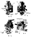
- Figure 2 is a global perspective view from a side of the apparatus of the present invention;
- Figure 3 is a global view, from another side, of the apparatus of the present invention;
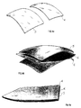
- Figures 4a through 4c schematically show the steps for assembling two glass panes and related PVB sheet to constitute a composite glass for a windshield;
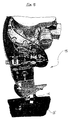
- Figure 5 is a view showing an automated head during the cutting of the excess PVB sheet from the edges of an assembled glass and according to the apparatus and the method of the present invention;
- Figure 6 is a partially sectioned view which shows in detail the step of cutting a PVB sheet from the edges of the glass assembled with the apparatus of the present invention;
- Figures 7a through 7c are schematic perspective views which partially show the automated head of Figure 5 for squaring the glass and according to the apparatus of the present invention; and
- Figure 8 is a schematic perspective view which partially shows the PVB sheet cutting head of the apparatus of the present invention.
- With reference not to Figures 1 and 2, the apparatus of the present invention is a compact apparatus for assembling composite glasses, which substantially consists of a set of automated cells which are physically closed in a stabilised hygro-thermostatic conduit (better illustrated below). The series of stations provides for the glass to be assembled, profiled and then delivered.
- It must be immediately stressed that the total size of each automated cell makes the apparatus particularly suitable for shipping inside standard transport containers.
- With reference now to Figure 3, the various stations constituting the cells are shown assembled according to the apparatus of the present invention. More specifically, the first station consists of a conveyor belt 1 in which the glass panes (i.e. the "inner glass" and the "outer glass") are loaded and are subsequently accelerated in a second station. A
steel structure 3, positioned superiorly to the first station 1, houses a tray with the stacked PVB sheets (said tray is not shown herein). - The glasses can be loaded via rack, manual or automated, or by the feeding conveyor belt external to the apparatus (not in the figure). Typical velocities of the input line are between 10 and 20 metres/min, whilst the output velocity from the second station is increased to 60 metres/min. On the other hand, the trays filled with one or more stacks of PVB can be loaded manually or automatically via flow connection conveyors and be replaced periodically.
- With particular reference to Figures 4a through 4c, the principle for the assembly of a composite glass according to the present invention is schematically shown therein. More specifically, two
glasses PVB sheet 6 is fed from thestation 3. It must be noted immediately that the dimensions of thePVB sheet 6 must exceed those of theglasses - Once the
glasses - With reference again to Figure 1, a third station is provided which consists of a squaring, or rather a calibration station, in which both
glass panes glass pane alignment station 7 at high speed, then is first slowed and lastly stopped by the conveyor belt of thestation 7. In this condition, the alignment is performed by means of servo-controlled tools, which are particular but known in the prior art, and able to handle the product which is extremely fragile. - In any case, a rapid operation is assured as required by the high production rate. The apparatus according to the present invention guarantees an exactness in the absolute references of each
glass pane - In regard to the
PVB sheet 6, once it is peeled from the stack in thestation 3, it enters a gripping andpositioning station 8 and after descent by means of detaching tools, it is positioned over a special belt. The determination of the position of the sheet according to the axes X and Y and its angling, as well as the detachment devices and the related applied technology, are comprised in a series of technologies which have already been covered by the patent application EP 1052206 A1 in the name of the present applicant and, therefore, their detailed description shall be omitted herein. - The two
glass panes subsequent assembly station 9. The first glass pane 4 (i.e. the inner glass) is transferred by handlinghead 10 which moves forward within the conveyor belt line. The glass is gripped again byappropriate suction cups 11. The second pane 5 (the outer glass) is then transferred by anupper handling head 12, which moves below the PVB peeler machine and above the line of theconveyor belt 9. In this case, too, the glass is gripped by thesuction cups 11. - Subsequently, the position of the
PVB sheet 6 is corrected and the sheet is transferred over the convex surface of theinner glass 4. In this station, viewing systems are used for this purposes for sensing the position and actual orientation of thePVB sheet 6 before it is gripped and handled by an appropriate manipulator tool. The correction of the position and orientation of thePVB sheet 6 aims at centring thesheet 6 relative to theglass 4 according to the Y and X axes, and to orient it about said centre. ThePVB sheet 6 is transferred by the belt onto the glass pane by a manipulator with four degrees of freedom which corrects the final position of the PVB sheet to combine the latter with the position of theglass 4 in theassembly station 9. This technology for the manipulation of the PVB sheet is also the subject of the patent application EP 1052206 A1 by the same applicant. - In this assembly station 9 a composite "sandwich" glass, comprising the two
glass panes PVB sheet 6 interposed between them, is assembled. - The assembly sequence is as follows:
- the
inner glass 4 is released from the lowerautomated head 10 onto asuction cup support 11; - the
PVB sheet 6 is positioned on the convex face of theinner glass 4 by the manipulator; - the
outer glass 5 is released over thePVB sheet 6 from the upperautomated head 11. - Since all components had been aligned previously, the maximum mounting error between the
glass panes PVB sheet 6 is 3 millimetres. - At this point, the windshield thus assembled is conveyed towards the subsequent
PVB cutting station 13 downstream. The windshield is transferred by an additionalautomated head 14, which performs an "exact" advancing motion relative to the initial position. This "exact" transfer of the windshield maintains all previous alignments obtained an maintained in the cuttingstation 13. All transfer movements of the automated heads are guided by controlled cycle motors to control the ends, the velocity and travel accelerations. - In said cutting
station 13, the final finishing operation is performed, i.e. the part of thePVB sheet 6 projecting out of the edges of the assembledpanes - With reference to Figure 5, an arm is illustrated therein which comprises a programmable
automated head 15. Theautomated head 15 is a 6-axis robot, and it is able to assure the necessary spaces between the glass and the edge of the PVB sheet as predetermined for each individual windshield model. Following the assembly of the composite glass, a predetermined minimal excess portion of PVB sheet is to be left along the entire profile of the glass edge, since further processes which follow (mainly sterilisation in an autoclave) usually entail a shrinking of the vinyl. - Moreover, it is possible to shave "down to zero" when there is no danger of shrinking or bending. For this purpose, a cutting
head 16 is provided, mounted on the automated head 15 (better illustrated below). - With reference not to Figures 6 through 8, the
automated head 15 and the cuttinghead 16 of the apparatus of the present invention are shown therein. - More specifically, to leave the exact quantity of
PVB sheet 6 projecting from the edge of theglass panes alignment region 17 is provided, mounted on the automated head and able to align the edges of theglass panes PVB sheet 6. Once an edge point of thepanes rotary cursors panes PVB sheet 6 positioned between them and thereby leading a determined quantity ofPVB sheet 6 projecting from the edges of thepanes - With particular reference to Figure 6, if the peripheral edge must be "shaved" down to zero (i.e. so that no part of
PVB sheet 6 projects from the edge of thepanes 4 and 5), ablade 160 projecting from theunderlying cutting head 16 cuts the quantity ofPVB sheet 6 projecting outwards whilst theautomated head 15 advances. The final result is a composite glass free ofexcess PVB sheet 6 projections. - The composite glass thus obtained is then fed by means of a conveyor belt 18 to a subsequent station for assembling the glass outside the apparatus of the present invention.
- The method and the apparatus of the present invention has innumerable advantage. A first advantage is provided by the extreme compactness of the apparatus, which makes it particularly suited to be transported in a single container.
- Another advantage is given by the simplicity and, at the same time, by the high reliability of the apparatus which make it particularly advantageous in terms of employment and operating costs.
Claims (1)
- A method for assembling a composite glass, characterised in that it comprises the following steps:feeding a pair of glass panes in a feeding station;accelerating said glass panes;precisely positioning said glass panes according to a reference station;feeding a sheet of plastic material on said glass panes from a plastic material sheet feeding station;assembling said composite glass positioning said plastic material sheet in calibrated fashion between said glass panes in a sandwich arrangement;conveying said glass thus assembled into a station for cutting the plastic material sheet;executing the peripheral cut of excess plastic material from the peripheral edges of the glass thus assembled; andfeeding the glass thus processed towards a subsequent mounting station.A method for assembling a composite glass as claimed in the previous claim, wherein said squaring step is performed by an automated head.A method for assembling a composite glass as claimed in claim 1 or 2, wherein said cutting step is performed by means of an automated head.A method for assembling a composite glass as claimed in any of the previous claims, further characterised in that it comprises a hygro-thermostatic control of at least a part of all the operative steps.An apparatus for assembling a composite glass, characterised in that it comprises:a station for feeding a pair of glass panes;a station for accelerating said pair of glass panes;a station for the calibrated positioning of said glass panes according to a reference station;a station for feeding a sheet of plastic material on said glass panes;a station for assembling said composite glass, in which said sheet of plastic material is positioned in calibrated fashion between said glass panes in a sandwich arrangement;a station for cutting the excess plastic material sheet from the peripheral edges of said composite glass thus assembled; anda station for feeding the glass thus processed towards a subsequent station for its mounting.An apparatus for assembling a composite glass as claimed in claim 5, wherein a hygro-thermostatic control of at least a part of all operative station is provided.An apparatus for assembling a composite glass as claimed in claim 5 or 6, further comprising at least an automated head in at least an operative station.
Applications Claiming Priority (2)
| Application Number | Priority Date | Filing Date | Title |
|---|---|---|---|
| IT2002RM000377A ITRM20020377A1 (en) | 2002-07-12 | 2002-07-12 | PROCESS AND ROBOTIC COMPACT EQUIPMENT FOR THE ASSEMBLY OF COMPOSITE GLASS. |
| ITRM20020377 | 2002-07-12 |
Publications (2)
| Publication Number | Publication Date |
|---|---|
| EP1382441A1 EP1382441A1 (en) | 2004-01-21 |
| EP1382441A9 true EP1382441A9 (en) | 2004-04-28 |
Family
ID=11456408
Family Applications (1)
| Application Number | Title | Priority Date | Filing Date |
|---|---|---|---|
| EP03077198A Withdrawn EP1382441A1 (en) | 2002-07-12 | 2003-07-11 | A process for the automated assembling of composite glasses and an automated apparatus therefor |
Country Status (2)
| Country | Link |
|---|---|
| EP (1) | EP1382441A1 (en) |
| IT (1) | ITRM20020377A1 (en) |
Families Citing this family (8)
| Publication number | Priority date | Publication date | Assignee | Title |
|---|---|---|---|---|
| FI118004B (en) * | 2004-11-09 | 2007-05-31 | Tamglass Ltd Oy | Method and apparatus for laminating glass sheets |
| DE102007003173B4 (en) * | 2006-12-08 | 2016-10-20 | Webasto Ag | Method and device for producing a glass / plastic composite |
| DE102008009843A1 (en) * | 2008-02-08 | 2009-08-13 | Bystronic Armatec Gmbh | cutter |
| DE102008031061A1 (en) | 2008-07-01 | 2011-01-05 | Grenzebach Maschinenbau Gmbh | Method and device for trimming photovoltaic modules |
| EP2174784A1 (en) | 2008-10-13 | 2010-04-14 | 3S Swiss Solar Systems AG | Procedure to remove a projecting section of a laminate layer |
| DE102008052319A1 (en) * | 2008-10-20 | 2010-04-22 | Hegla Gmbh & Co. Kg | Apparatus and method for removing film overhang on a glass edge of a laminated safety glass panel |
| FR2993197B1 (en) * | 2012-07-11 | 2015-02-13 | Saint Gobain | DEVICE AND METHOD FOR CUTTING PLASTIC MATERIAL, ESPECIALLY LAMINATED GLAZING |
| CN113021963B (en) * | 2021-04-25 | 2023-09-29 | 北京新远建邦科技有限公司 | Semi-automatic production line for producing composite heat-insulation groove plates |
Family Cites Families (6)
| Publication number | Priority date | Publication date | Assignee | Title |
|---|---|---|---|---|
| FR2510029A1 (en) * | 1981-07-24 | 1983-01-28 | Saint Gobain Vitrage | Automatic trimming of film from laminated glass borders - using self-aligning, self-propelled cutting head |
| NZ201127A (en) * | 1981-07-28 | 1986-03-14 | Ppg Industries Inc | Assembling flexible material with a bent glass sheet or sheets to form laminated windscreen |
| FR2594812B1 (en) * | 1986-02-27 | 1988-05-27 | Saint Gobain Vitrage | PROCESS AND DEVICE FOR THE AUTOMATIC ASSEMBLY OF LAMINATED WINDOWS |
| DE3728284A1 (en) * | 1987-08-25 | 1989-04-27 | Flachglas Ag | Assembly device |
| IT1230916B (en) * | 1988-06-27 | 1991-11-08 | Central Glass Co Ltd | DEVICE AND METHOD FOR CUTTING SUPERFLUOUS EDGE PART OF LAMINATED GLASS INTERLAY |
| US5556505A (en) * | 1994-07-05 | 1996-09-17 | Ford Motor Company | Windshield assembly system |
-
2002
- 2002-07-12 IT IT2002RM000377A patent/ITRM20020377A1/en unknown
-
2003
- 2003-07-11 EP EP03077198A patent/EP1382441A1/en not_active Withdrawn
Also Published As
| Publication number | Publication date |
|---|---|
| ITRM20020377A0 (en) | 2002-07-12 |
| ITRM20020377A1 (en) | 2004-01-12 |
| EP1382441A1 (en) | 2004-01-21 |
Similar Documents
| Publication | Publication Date | Title |
|---|---|---|
| EP2861361B1 (en) | Blanking line and method for stacking blanks outputted from a blanking shear or press | |
| CN109638359B (en) | Die cutting lamination integrated forming process | |
| EP1382441A9 (en) | A process for the automated assembling of composite glasses and an automated apparatus therefor | |
| CN110509604B (en) | Forming and defoaming machine for leather case packaging box and using method thereof | |
| CN112296672B (en) | Flexible automatic stamping assembly production line for embedded disinfection cabinet | |
| CN107089359B (en) | Automatic production line | |
| CN212504583U (en) | Glass cutting processing line | |
| CN115610895A (en) | Flexible cargo replenishing method and device | |
| CN114300801B (en) | Battery cell packaging device | |
| CN107117345B (en) | Device and method for automatically pasting back adhesive and protective film | |
| CN107352817A (en) | A kind of novel automobile sandwich glass automatic sheet binding apparatus and method | |
| CN214357197U (en) | Packaging production line for disc-packed products | |
| EP3253511B1 (en) | Method for loading blanks to a press and system | |
| CN210475294U (en) | Material feeding unit and have this material feeding unit's punching press workstation | |
| CN210000719U (en) | Paste mark production line and paste mark device | |
| CN206969057U (en) | Automatic patch gum and protection film device | |
| CN107598561B (en) | A kind of assembling monitoring method of the circlip buckle and screw of automobile door plate | |
| CN112912311A (en) | Transport system for transporting workpieces on a transport path between two processing stations | |
| CN116991134B (en) | Method and system for changing product on production line | |
| CN216398895U (en) | Automatic part machining and assembling production line | |
| CN215317465U (en) | Numerical control cutter passivation process mechanical device | |
| KR20190111721A (en) | Automatic taping system for bag-packed product | |
| CN219487937U (en) | Improved cigarette packaging box throwing system | |
| CN218615245U (en) | Automatic processing system for injection molding products | |
| CN217349507U (en) | Semiconductor element transfer apparatus |
Legal Events
| Date | Code | Title | Description |
|---|---|---|---|
| PUAI | Public reference made under article 153(3) epc to a published international application that has entered the european phase |
Free format text: ORIGINAL CODE: 0009012 |
|
| AK | Designated contracting states |
Kind code of ref document: A1 Designated state(s): AT BE BG CH CY CZ DE DK EE ES FI FR GB GR HU IE IT LI LU MC NL PT RO SE SI SK TR |
|
| AX | Request for extension of the european patent |
Extension state: AL LT LV MK |
|
| 17P | Request for examination filed |
Effective date: 20040714 |
|
| AKX | Designation fees paid |
Designated state(s): AT BE BG CH CY CZ DE DK EE ES FI FR GB GR HU IE IT LI LU MC NL PT RO SE SI SK TR |
|
| 17Q | First examination report despatched |
Effective date: 20050608 |
|
| STAA | Information on the status of an ep patent application or granted ep patent |
Free format text: STATUS: THE APPLICATION IS DEEMED TO BE WITHDRAWN |
|
| 18D | Application deemed to be withdrawn |
Effective date: 20051220 |