EP1381109A1 - Procédé pour commander des éléments déphaseurs a férrite, dispositifs de mise en oeuvre, et leurs applications - Google Patents
Procédé pour commander des éléments déphaseurs a férrite, dispositifs de mise en oeuvre, et leurs applications Download PDFInfo
- Publication number
- EP1381109A1 EP1381109A1 EP03291615A EP03291615A EP1381109A1 EP 1381109 A1 EP1381109 A1 EP 1381109A1 EP 03291615 A EP03291615 A EP 03291615A EP 03291615 A EP03291615 A EP 03291615A EP 1381109 A1 EP1381109 A1 EP 1381109A1
- Authority
- EP
- European Patent Office
- Prior art keywords
- phase
- elements
- temperature
- control
- ferrite
- Prior art date
- Legal status (The legal status is an assumption and is not a legal conclusion. Google has not performed a legal analysis and makes no representation as to the accuracy of the status listed.)
- Granted
Links
- 229910000859 α-Fe Inorganic materials 0.000 title claims description 65
- 238000000034 method Methods 0.000 title claims description 17
- 230000010363 phase shift Effects 0.000 claims abstract description 56
- 230000003247 decreasing effect Effects 0.000 claims description 3
- 238000003780 insertion Methods 0.000 description 11
- 230000037431 insertion Effects 0.000 description 11
- 238000010586 diagram Methods 0.000 description 7
- 230000005415 magnetization Effects 0.000 description 7
- 239000000463 material Substances 0.000 description 7
- 230000000295 complement effect Effects 0.000 description 6
- 239000002131 composite material Substances 0.000 description 6
- PXHVJJICTQNCMI-UHFFFAOYSA-N Nickel Chemical compound [Ni] PXHVJJICTQNCMI-UHFFFAOYSA-N 0.000 description 4
- 239000006185 dispersion Substances 0.000 description 4
- 238000004519 manufacturing process Methods 0.000 description 3
- 230000035945 sensitivity Effects 0.000 description 3
- 229910052688 Gadolinium Inorganic materials 0.000 description 2
- WHXSMMKQMYFTQS-UHFFFAOYSA-N Lithium Chemical compound [Li] WHXSMMKQMYFTQS-UHFFFAOYSA-N 0.000 description 2
- 229910052782 aluminium Inorganic materials 0.000 description 2
- XAGFODPZIPBFFR-UHFFFAOYSA-N aluminium Chemical compound [Al] XAGFODPZIPBFFR-UHFFFAOYSA-N 0.000 description 2
- 230000009977 dual effect Effects 0.000 description 2
- UIWYJDYFSGRHKR-UHFFFAOYSA-N gadolinium atom Chemical compound [Gd] UIWYJDYFSGRHKR-UHFFFAOYSA-N 0.000 description 2
- 229910052744 lithium Inorganic materials 0.000 description 2
- 229910052759 nickel Inorganic materials 0.000 description 2
- FYYHWMGAXLPEAU-UHFFFAOYSA-N Magnesium Chemical compound [Mg] FYYHWMGAXLPEAU-UHFFFAOYSA-N 0.000 description 1
- 241000135309 Processus Species 0.000 description 1
- RTAQQCXQSZGOHL-UHFFFAOYSA-N Titanium Chemical compound [Ti] RTAQQCXQSZGOHL-UHFFFAOYSA-N 0.000 description 1
- 240000008042 Zea mays Species 0.000 description 1
- 230000006978 adaptation Effects 0.000 description 1
- 239000004411 aluminium Substances 0.000 description 1
- 230000000712 assembly Effects 0.000 description 1
- 238000000429 assembly Methods 0.000 description 1
- 230000003416 augmentation Effects 0.000 description 1
- 238000009529 body temperature measurement Methods 0.000 description 1
- 238000011088 calibration curve Methods 0.000 description 1
- 230000015556 catabolic process Effects 0.000 description 1
- 238000006731 degradation reaction Methods 0.000 description 1
- 239000003989 dielectric material Substances 0.000 description 1
- 230000000694 effects Effects 0.000 description 1
- 230000001939 inductive effect Effects 0.000 description 1
- 229910052749 magnesium Inorganic materials 0.000 description 1
- 239000011777 magnesium Substances 0.000 description 1
- 238000005259 measurement Methods 0.000 description 1
- 229910052751 metal Inorganic materials 0.000 description 1
- 239000002184 metal Substances 0.000 description 1
- 150000002739 metals Chemical class 0.000 description 1
- 230000001902 propagating effect Effects 0.000 description 1
- 239000000523 sample Substances 0.000 description 1
Images




Classifications
-
- H—ELECTRICITY
- H01—ELECTRIC ELEMENTS
- H01P—WAVEGUIDES; RESONATORS, LINES, OR OTHER DEVICES OF THE WAVEGUIDE TYPE
- H01P1/00—Auxiliary devices
- H01P1/18—Phase-shifters
- H01P1/19—Phase-shifters using a ferromagnetic device
- H01P1/195—Phase-shifters using a ferromagnetic device having a toroidal shape
Definitions
- the invention relates to microwave phase shifters at toroid of ferrite, used in radars, beams radio and telecommunications systems, in particular particular for network antennas capable of providing function of electronic scanning antennas, as well as for switches and dividers of varying power using this type of phase shifter.
- the toroidal phase shifter consists of a toroid of ferrite (1) placed around a dielectric (3) in the center of a waveguide (2) with rectangular cross-section propagating the TE01 mode. In this case, the toroid does not fill not the entire section of the waveguide.
- This type of phase shifter operates with a linearly polarized wave.
- the double toroid structure allows better compactness and miniaturization. It consists of a blade of dielectric (3) sandwiched between two cores of ferrite (1,1 '), the assembly being placed in a waveguide (2) rectangular cross section.
- the phase shift is obtained by a change of magnetization in the two tori of ferrite thus creating a variation of the constant of propagation of the microwave wave that passes through it.
- the variation of magnetization is obtained by a variation of transverse magnetic field, itself produced by the passage a current flowing through an electric wire (not shown) passing longitudinally ferrite toroids.
- the shape of the ferrite toroid makes it possible to conserve magnetization in the absence of current. This is what we calls a "latching" operation.
- the phase shifter thus obtained is a non-reciprocal phase shifter, this means that for a given direction of current, the phase shift obtained is different depending on the direction of propagation of the microwave wave.
- phase shift sensitivity of these phase shifters to effects of temperature is their major drawback in applications where the operating temperature may vary over a greater or lesser range, generally from -20 ° C to + 80 ° C, in telecommunications or radar. This sensitivity is due to variations in the characteristics of the Ferrite material as a function of temperature.
- the invention aims to provide a new solution to this problem, free from the above disadvantages, and suitable for a temperature range of -20 ° C to + 80 ° C.
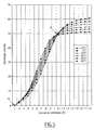
- the invention is based on the discovery that there is a value of the control energy of a phase-shifter ferrite toroidal microwave operating in residual condition for which the phase shift is almost insensitive to the temperature, at least in the range of -20 ° C to + 80 ° C, and that the variation of the phase shift with the temperature for a given control energy is increasing function or decreasing function of temperature depending on whether the energy command is less than or greater than the value aforementioned insensitivity.
- phase shifter controls the phase shifter with the control energy that corresponds to its point of insensitivity (first solution) or by associating in series at least two identical or substantially phase-shifting elements identical and controlling them with energies of different command such as the elements work respectively one in an area where the phase shift is a increasing function of the temperature and the other in a area where the phase shift is a decreasing function of the temperature, the control energies being chosen from so that the phase shift gradients as a function of the offset each other (second solution, commands complementary).
- the first point (A) is obtained by considering a ferrite double toroid phase shifter element mounting where the direction of extension is the same as the sense of current of initialization command applied (RESET): the double toroidal ferrite is remanently controlled by a current pulse of given duration and value, to initialize ferrite and start a state given and known reference. We will call this impulse, "Reset pulse”.
- the phase difference obtained after this reset pulse is independent of magnetization ferrite and serves as a point of reference for the phase shift curve as a function of the current of ordered.
- the curves intersect in two points: the first point (A) and the second point (B) insensitivity "which depends only on the characteristics intrinsic properties of ferrite.
- phase shifter By associating several bi-phase phase shifters of this type, we get a digital phase shifter insensitive to the temperature. This gives precisions of phase shift of the order of +/- 3 ° over 360 ° and over a temperature range of - 20 ° C to + 80 ° C, whereas for a conventional phase shifter without correction, the accuracy of the phase shift is of the order of +/- 40 °.
- the element seen from above is constituted two ferrite cores (1,1 ') separated by a dielectric (3) high permittivity, in a waveguide rectangular (2).
- Reference (6) designates in the figure the wire of the order.
- Figures 7 to 9 relate to the second solution provided by the invention.
- FIG. 7 is a diagram of a constituted device, according to the second solution of the invention, two toroidal phase shifter elements (D, D ') separated by a dielectric (3) associated in series in a waveguide (2).
- Each element has two ferrite cores (1,1 ') placed around a dielectric (3) of high permittivity and separated by a dielectric (3 ') ensuring the adaptation of two elements.
- the elements are controlled by circuits distinct control lines which have been shown control (6,6 ').
- the invention allows the production of phase shifters temperature-insensitive digital devices, each bit of which is consisting of two elements controlled by energies of complementary control (Figure 9).
- phase shifter insensitive to temperature for a certain range of phase shift.
- phase shifter element analog temperature-insensitive on some temperature range, as opposed to a digital phase shifter operating in two phases (2 states).
- This device for phase shifter ferrite controlled in remanent has another quality: the stability of the phase insertion according to the temperature. All the Previous discoveries focused on phase shift differential as a function of temperature. This stability of the insertion phase is observed for a point of given operation, where insertion losses are minimum. Additional measures have shown that the insertion phase varies extremely little depending on the temperature, which is an important element for large network antennas, where there may be a gradient of temperature between phase shifters, inducing misalignment untimely by variation of the phase. To put in evidence this stability of the insertion phase, it takes locate the operating point, determined by losses insertion distances, for a control current direction and a given direction of propagation.
- phase shifter insensitive to the temperature has been carried out.
- a bit of phase shift is achieved, either from a bi-phase element who is himself insensitive to temperature, either from two complementary control elements. Both techniques were used to make this model of phase shifter insensitive to temperature.
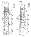
- the 4-bit model was realized with 7 sections of phase shift.
- the three most significant bits are each consisting of two complementary control elements and the bit of low weight (22 ° 5) is constituted by a bi-phase element. This can ensure sufficient accuracy (+/- 1 °) and it has the advantage of having only one section.
- the different sections are separated by elements low loss dielectrics (magnesium titanate permittivity 13). They have been sized to ensure continuity of impedance in the structure of the phase-shifter full. They are also useful for facilitating the passage control wires.
- the schema of the completed model is presented figure 10.
- the phase shifter works in latching mode and the right section is dimensioned according to the rules conventional dimensioning.
- the control energy is provided by a pulse of programmable current.
- the remanent mode command uses current sequences of opposite sign: (RESET / SET - Boot / phase).
- phase shift created depends on the direction of propagation in the phase shifter (advance and phase delay). Even though phase shift curves according to the control current have the same pace (with the sign close) for both directions of propagation, it is necessary to operate the phase-shifter so that the direction of propagation is the same as the direction of control current. For RESET mode, these operating conditions ensure good stability of the reference insertion phase depending on the temperature.
- Figures 11 and 12 show the differential phase difference measured sections 1 and 2 of bit 4 according to the temperature.
- the differential phase difference values are obtained by adding the different bits.
- the maximum deviation of each of the phase shift values in the temperature range from -20 ° C to + 60 ° C is shown in the following table: States of phase shift 0 ° 22 5 45 ° 67 ° 5 90 112 ° 5 135 ° 157 ° 5 Maximum differences 0 ° 2 6 1 1 3 # 6 1 5 4 ° 2 1 4 5 States of phase shift 180 ° 202 ° 5 225 ° 247 ° 5 270 ° 292 ° 5 315 ° 337 ° 5 Maximum differences 2 7 1 2 2 1 3 1 8 2 # 3 1 1 2 5
- the maximum peak-to-peak deviation is less than 6 °.
- the precision of each of the 15 values of phase shifts (non-zero) is better than +/- 3 ° for the range temperature from -20 ° C to + 60 ° C. In the same way, we gets virtually the same accuracy for the extended range from -20 ° C to + 80 ° C.
- the 180 ° bit can operate from 165 ° to 202 ° provided that the pairs values of the control current. It is the same for bits 90 ° and 45 °.
- the typical precision obtained on this model is better than +/- 3 ° in the temperature range of -20 ° C to + 60 ° C.
- the invention is not limited to the achievements that have have been described.
Landscapes
- Variable-Direction Aerials And Aerial Arrays (AREA)
Abstract
Description
- structure compacte, miniaturisée, dont les dimensions sont compatibles avec le maillage d'une antenne réseau à balayage électronique un ou deux plans ;
- faibles pertes d'insertion ;
- mode de fonctionnement en rémanent (« latching ferrite phase shifter ») : l'énergie de commande n'a pas besoin d'être maintenue pendant la durée où le déphasage est nécessaire ;
- faible consommation en énergie de commande et simplicité de la commande ; la commande est impulsionnelle, il n'est donc pas nécessaire de maintenir un courant en continu ;
- temps de commutation très faible, de l'ordre de quelques microsecondes, avec une électronique de commande relativement simple et classique ;
- grand facteur d'efficacité du déphasage par unité de longueur (en degré/cm) ;
- peu de dispersion en fonction de la fréquence : pour une énergie de commande donnée, le retard varie extrêmement peu en fonction de la fréquence.
- la figure 1 est un schéma d'un déphaseur à simple toroïde ;
- la figure 2 est un schéma d'un déphaseur à double toroïde ;
- la figure 3 est un schéma d'une structure compacte de déphaseur à double toroïde ;
- la figure 4 est un schéma d'une structure composite à circuit de commande identique à la structure compacte.
- utiliser un matériau ferrite dont les grandeurs caractéristiques, l'aimantation à la saturation (411 Ms) et l'aimantation rémanente Br varient peu en fonction de la température. Malheureusement, cette technique n'est pas parfaite, car les caractéristiques ne sont pas constantes en fonction de la température. En outre, pour des matériaux ferrite utilisés pour des fréquences supérieures à 10 GHz, qui sont en général des ferrites de lithium ou de nickel, les caractéristiques de ces ferrites varient de façon monotone. Il n'y a donc aucune compensation possible. En effet, les techniques de compensation qui consistent à doper le matériau ferrite par des métaux (aluminium ou gadolinium) s'accompagnent généralement d'une augmentation des pertes diélectriques et magnétiques. Ces pertes deviennent inacceptables pour des fréquences élevées.
- associer un ferrite hyperfréquence (1) et un matériau ferrite basse fréquence (5) servant de circuit magnétique de commande (fig.4). En choisissant un matériau ferrite de caractéristiques appropriées en fonction de la température, on peut obtenir une certaine compensation en température. Cependant, cette technique a d'énormes inconvénients. En premier lieu, la structure composite n'est pas compacte, ce qui augmente le volume et la masse. Cette technique pose également des problèmes de reproductibilité pour un processus de fabrication industrielle, étant donnée la nécessité de maítriser les dimensions d'un entrefer. Par ailleurs, un toroïde composite nécessite une énergie de commande extrêmement élevée par rapport à un toroïde de ferrite compact constitué uniquement par un ferrite hyperfréquence où l'aimantation rémanente est assurée naturellement. Ceci est dû à la présence de l'entrefer.
- faire une correction en température en temps réel. Ainsi, dans un réseau d'antennes comportant N déphaseurs par exemple, chaque déphaseur est caractérisé individuellement en température. Les courbes de déphasage en fonction de la commande électronique pour différentes températures sont relevées et mises en mémoire dans une EPROM. Une sonde de mesure de température en temps réel permet de connaítre à tout instant la température effective du déphaseur et d'en déduire la loi de commande appropriée pour obtenir un déphasage constant, en fonction des informations mémorisées. Cette technique peut être satisfaisante, à condition d'avoir des lois de commande identiques pour tous les déphaseurs du réseau. Dans des cas où il existe un gradient de température au sein de l'antenne réseau, chacun des déphaseurs doit posséder sa propre loi de correction, ce qui devient très vite compliqué et coûteux et de ce fait, limite la précision de correction possible.
- la figure 5 est un schéma des courbes de déphasage d'un élément déphaseur ferrite en fonction du courant de commande, selon différentes températures ; compte tenu de l'électronique de commande utilisée les courbes sont graduées en courant de commande, correspondant à l'énergie de commande nécessaire. On parlera dans la suite soit de l'énergie de commande, soit du courant de commande correspondant.
- la figure 6 est un exemple d'un déphaseur à double toroïde de ferrite fonctionnant en rémanent selon la première solution de l'invention ;
- la figure 7 est une coupe longitudinale d'un guide d'onde comportant deux éléments déphaseurs non réciproques à double toroïde de ferrite associés selon la deuxième solution de l'invention ;
- la figure 8 est une coupe d'un dispositif analogue à celle de la figure 7 mais avec un seul fil de commande ;
- la figure 9 est un exemple d'un déphaseur numérique 4 bits fonctionnant en rémanent constitué d'une pluralité d'éléments compensés en température (structure à double toroïde de ferrite en guide rectangulaire);
- la figure 10 est un exemple d'une maquette de déphaseur 4 bits comprenant un bit constitué d'un élément bi-phase et des bits constitués d'éléments à commande complémentaire ;
- les figures 11 et 12 représentent le déphasage différentiel mesuré du premier et du deuxième tronçon du bit 4 du déphaseur de la figure 10 en fonction de la température, et
- la figure 13 représente les 16 étapes de déphasages différentiels (4 bits) en fonction de la température.
- une impulsion de reset ;
- une impulsion de signe opposé à l'impulsion de reset, de durée donnée et de valeur appelée « courant de commande ».
- déphasage différentiel nul,
- déphasage différentiel fixe, dont la valeur dépend de la longueur du ferrite et peut donc être ajustée selon le besoin.
- Bit 1 (22°5) élément bi-phase à 1 tronçon de longueur
1,4mm. Cet élément a été obtenu suivant le principe de la
figure 5 en ajustant la longueur. On obtient ainsi un
biphase à
22,5° +/- 0,5°. - Bit 2 (45°) à 2 tronçons de longueur : L1 = 2mm et L2= 1, 5mm
- Bit 3 (90°) à 2 tronçons de longueur : L1= 4,2mm et L2= 3mm
- Bit 4(180°) à 2 tronçons de longueur : L1=7,4mm et L2=6mm
- Bit 1 (22,5°) élément bi-phase à partir du 7ème tronçon (1,4mm) avec un courant de commande de 0,85A
- Bit 2 (45°) à partir de 2 tronçons : 5 (2mm) avec 1,3A et 6 (1,5mm) avec 0,53A
- Bit 3 (90°) à partir de 2 tronçons : 3 (4,2mm) avec 0,67A et 4 (3mm) avec 1, 08A
- Bit 4 (180°) à partir de 2 tronçons : 1 (7,4mm) avec 0,88A et 2 (6mm) avec 1,8A
| Etats de déphasage | 0° | 22°5 | 45° | 67°5 | 90° | 112°5 | 135° | 157°5 |
| Ecarts maximaux | 0° | 2°6 | 1°1 | 3°6 | 1°5 | 4° | 2°1 | 4°5 |
| Etats de déphasage | 180° | 202°5 | 225° | 247°5 | 270° | 292°5 | 315° | 337°5 |
| Ecarts maximaux | 2°7 | 1°2 | 2°1 | 3° | 1°8 | 2°3 | 1°1 | 2°5 |
| Etats de déphasage | 0° | 22°5 | 45° | 67°5 | 90° | 112°5 | 135° | 157°5 |
| Ecarts maximaux de - 20°C à +60°C | 0° | 1°9 | 1°6 | 3°6 | 2° | 1° | 3°4 | 3°5 |
| Ecarts maximaux de -20°C à +80°C | 0° | 2°6 | 1°6 | 3°6 | 3°5 | 3°4 | 4°9 | 2° |
| Etats de déphasage | 180° | 202°5 | 225° | 247°5 | 270° | 292°5 | 315° | 337°5 |
| Ecarts maximaux de -20°C à +60°C | 2° | 2°2 | 3°1 | 2°8 | 4° | 4°2 | 5°4 | 5°2 |
| Ecarts maximaux de -20°C à +80°C | 3°6 | 3°5 | 3°1 | 4°5 | 4° | 5°5 | 5°4 | 6°9 |
- Le bit 180° de 165° à 202°
- Le bit 90° de 90° à 107°
- Le bit 45° de 45° à 55°
- Le bit 22°5 (bi-phase)
Claims (15)
- Procédé pour commander avec une énergie de commande un élément déphaseur hyperfréquences à toroïde de ferrite, dans lequel on détermine la valeur de l'énergie de commande pour laquelle le déphasage est à peu près insensible à la température et, soit on commande l'élément avec cette valeur, soit on lui associe en série un autre élément déphaseur identique (ou sensiblement identique) et on commande les deux éléments avec des énergies de commande de valeurs respectivement inférieure et supérieure à ladite valeur en sorte que les gradients de déphasage des deux éléments en fonction de la température se compensent.
- Procédé selon la revendication 1, dans lequel on commande l'élément avec une énergie de commande choisie pour que le déphasage résultant soit à peu près insensible aux variations de température.
- Procédé selon la revendication 1, dans lequel on associe en série au moins deux éléments identiques ou sensiblement identiques et on commande ces éléments avec des énergies de commande telles que les gradients de déphasage des deux éléments en fonction de la température se compensent.
- Procédé selon la revendication 3, dans lequel on commande les deux éléments par des fils de commande distincts parcourus par des courants d'intensité différents.
- procédé selon la revendication 3, dans lequel on commande les deux éléments par un fil de commande commun qui réalise autour des ferrites des nombres entiers différents de tours.
- Dispositif déphaseur à ferrite (1,1') commandé électriquement, caractérisé en ce qu'il comprend au moins deux éléments déphaseurs à ferrite (D,D') identiques ou sensiblement identiques associés en série et commandés avec des énergies de commande différentes telles que les éléments fonctionnent respectivement l'un dans une zone où le déphasage est une fonction croissante de la température et l'autre dans une zone où le déphasage est une fonction décroissante de la température, les énergies de commande étant choisies en sorte que les gradients de déphasage des deux éléments en fonction de la température se compensent.
- Dispositif selon la revendication 6, dont les deux éléments déphaseurs (D,D') sont commandés par des fils de commande distincts (6,6') où circulent des courants de commande différents.
- Dispositif selon la revendication 6, dont les deux éléments déphaseurs sont commandés par un fil de commande commun (6) où circule un même courant de commande mais qui réalise autour des ferrites des nombres entiers différents de tours.
- Dispositif selon la revendication 6, dont les éléments déphaseurs fonctionnent en analogique.
- Dispositif selon l'une des revendications 6 à 9, dont chaque élément déphaseur est un déphaseur non réciproque qui comprend un seul tore de ferrite (1).
- Dispositif selon l'une des revendications 6 à 9, dont chaque élément déphaseur est un déphaseur non réciproque à double tore (1,1') de ferrite.
- Dispositif selon l'une des revendications 6 à 8 qui comprend plusieurs couples d'éléments déphaseurs (D1, D'1, D2, D'2, D3, D'3, D4, D'4) associés deux à deux pour constituer un déphaseur numérique.
- Dispositif déphaseur à ferrite commandé électriquement, caractérisé en ce qu'il est commandé avec une énergie de commande choisie en sorte que le déphasage soit à peu près indépendant de la température.
- Dispositif selon la revendication 13, dont les éléments déphaseurs fonctionnent en bi phase.
- Applications d'un dispositif déphaseur selon l'une des revendications 6 à 14 à un radar, un faisceau hertzien, une antenne ou un commutateur.
Applications Claiming Priority (2)
| Application Number | Priority Date | Filing Date | Title |
|---|---|---|---|
| FR0208195 | 2002-07-01 | ||
| FR0208195A FR2841687B1 (fr) | 2002-07-01 | 2002-07-01 | Procede pour commander des elements dephaseurs a ferrite, dispositifs de mise en oeuvre, et leurs applications |
Publications (2)
| Publication Number | Publication Date |
|---|---|
| EP1381109A1 true EP1381109A1 (fr) | 2004-01-14 |
| EP1381109B1 EP1381109B1 (fr) | 2005-06-29 |
Family
ID=29725039
Family Applications (1)
| Application Number | Title | Priority Date | Filing Date |
|---|---|---|---|
| EP20030291615 Expired - Lifetime EP1381109B1 (fr) | 2002-07-01 | 2003-07-01 | Procédé pour commander des éléments déphaseurs a férrite, dispositifs de mise en oeuvre, et leurs applications |
Country Status (3)
| Country | Link |
|---|---|
| EP (1) | EP1381109B1 (fr) |
| DE (1) | DE60300916T2 (fr) |
| FR (1) | FR2841687B1 (fr) |
Citations (2)
| Publication number | Priority date | Publication date | Assignee | Title |
|---|---|---|---|---|
| GB1216841A (en) * | 1967-01-20 | 1970-12-23 | Emi Ltd | Improvements in or relating to micro-wave phase shifters |
| US3824502A (en) * | 1973-04-11 | 1974-07-16 | Us Air Force | Temperature compensated latching ferrite phase shifter |
-
2002
- 2002-07-01 FR FR0208195A patent/FR2841687B1/fr not_active Expired - Fee Related
-
2003
- 2003-07-01 EP EP20030291615 patent/EP1381109B1/fr not_active Expired - Lifetime
- 2003-07-01 DE DE2003600916 patent/DE60300916T2/de not_active Expired - Lifetime
Patent Citations (2)
| Publication number | Priority date | Publication date | Assignee | Title |
|---|---|---|---|---|
| GB1216841A (en) * | 1967-01-20 | 1970-12-23 | Emi Ltd | Improvements in or relating to micro-wave phase shifters |
| US3824502A (en) * | 1973-04-11 | 1974-07-16 | Us Air Force | Temperature compensated latching ferrite phase shifter |
Non-Patent Citations (1)
| Title |
|---|
| JONG-MIN PARK ET AL: "X-BAND FERRITE PHASE SHIFTER IN WAVEGUIDE GEOMETRY", PROCEEDINGS OF THE REGION TEN CONFERENCE (TENCON). BEIJING, OCT. 19 - 21, 1993, BEIJING, IAP, CN, vol. 3, 19 October 1993 (1993-10-19), pages 464 - 467, XP000521462, ISBN: 0-7803-1233-3 * |
Also Published As
| Publication number | Publication date |
|---|---|
| DE60300916T2 (de) | 2006-07-20 |
| FR2841687A1 (fr) | 2004-01-02 |
| DE60300916D1 (de) | 2005-08-04 |
| FR2841687B1 (fr) | 2004-09-17 |
| EP1381109B1 (fr) | 2005-06-29 |
Similar Documents
| Publication | Publication Date | Title |
|---|---|---|
| Bilotti et al. | Equivalent-circuit models for the design of metamaterials based on artificial magnetic inclusions | |
| CA1338792C (fr) | Dephaseur hyperfrequence a microruban et dielectrique suspendu, et application a des reseaux d'antennes a balayage de lobe | |
| EP0708492B1 (fr) | Antenne à microbande notamment pour des applications horlogères | |
| EP1556946B1 (fr) | Dispositif a ondes magnetostatiques base sur des films minces metalliques, procede de fabrication et application a des dispositfs de traitement de signaux hyperfrequences | |
| EP1723693B1 (fr) | Antenne a depointage variable comprenant au moins un element dephaseur | |
| FR2522446A1 (fr) | Dephaseur a dephasage variable, utilisable notamment dans un systeme d'antennes pour radar | |
| EP2178152A1 (fr) | Dispositif de commutation électronique pour signaux a haute fréquence | |
| EP1381109B1 (fr) | Procédé pour commander des éléments déphaseurs a férrite, dispositifs de mise en oeuvre, et leurs applications | |
| FR2866979A1 (fr) | Composants supraconducteurs en couches minces a inductance accordable, procede de realisation et dispositifs incluant de tels composants | |
| FR2831734A1 (fr) | Dispositif pour la reception et/ou l'emission de signaux electromagnetiques a diversite de rayonnement | |
| EP0073165B1 (fr) | Commutateur d'ondes électromagnétiques | |
| FR2629641A1 (fr) | Circuit dephaseur hyperfrequence | |
| FR2589650A1 (fr) | Circuit a ligne microbande resonnante | |
| EP1844499B1 (fr) | Utilisation de composants supraconducteurs en couches minces comme inductance variable, dispositifs incluant de tels composants, et procede de commande associe | |
| EP0013223B1 (fr) | Dispositif de filtrage d'harmoniques pour émetteur radioélectrique | |
| EP2853004B1 (fr) | Synthétiseur d'impédance coaxial | |
| FR2668304A1 (fr) | Dephaseur reciproque en guide dielectrique a ferrite. | |
| Erickson et al. | A low-loss 74–110-GHz Faraday polarization rotator | |
| FR2519475A1 (fr) | Dispositif selectif accordable a ondes magnetostatiques de volume | |
| FR2698479A1 (fr) | Composite hyperfréquence anisotrope. | |
| EP3667808A1 (fr) | Dispositif de dephasage mecanique large bande en onde guidee | |
| EP2462701B1 (fr) | Circuit de commutation pour des signaux large bande | |
| FR2610766A1 (fr) | Filtre hyperfrequence, accordable electroniquement | |
| EP1956682B1 (fr) | Antenne monopôle à commutation | |
| FR2521786A2 (fr) | Filtre passe-bande a resonateurs dielectriques |
Legal Events
| Date | Code | Title | Description |
|---|---|---|---|
| PUAI | Public reference made under article 153(3) epc to a published international application that has entered the european phase |
Free format text: ORIGINAL CODE: 0009012 |
|
| AK | Designated contracting states |
Kind code of ref document: A1 Designated state(s): AT BE BG CH CY CZ DE DK EE ES FI FR GB GR HU IE IT LI LU MC NL PT RO SE SI SK TR |
|
| AX | Request for extension of the european patent |
Extension state: AL LT LV MK |
|
| 17P | Request for examination filed |
Effective date: 20040618 |
|
| AKX | Designation fees paid |
Designated state(s): DE FR GB IT |
|
| GRAP | Despatch of communication of intention to grant a patent |
Free format text: ORIGINAL CODE: EPIDOSNIGR1 |
|
| GRAS | Grant fee paid |
Free format text: ORIGINAL CODE: EPIDOSNIGR3 |
|
| GRAA | (expected) grant |
Free format text: ORIGINAL CODE: 0009210 |
|
| AK | Designated contracting states |
Kind code of ref document: B1 Designated state(s): DE FR GB IT |
|
| REG | Reference to a national code |
Ref country code: GB Ref legal event code: FG4D Free format text: NOT ENGLISH |
|
| REF | Corresponds to: |
Ref document number: 60300916 Country of ref document: DE Date of ref document: 20050804 Kind code of ref document: P |
|
| GBT | Gb: translation of ep patent filed (gb section 77(6)(a)/1977) |
Effective date: 20051010 |
|
| PLBE | No opposition filed within time limit |
Free format text: ORIGINAL CODE: 0009261 |
|
| STAA | Information on the status of an ep patent application or granted ep patent |
Free format text: STATUS: NO OPPOSITION FILED WITHIN TIME LIMIT |
|
| 26N | No opposition filed |
Effective date: 20060330 |
|
| REG | Reference to a national code |
Ref country code: FR Ref legal event code: AU |
|
| REG | Reference to a national code |
Ref country code: FR Ref legal event code: PLFP Year of fee payment: 14 |
|
| REG | Reference to a national code |
Ref country code: FR Ref legal event code: PLFP Year of fee payment: 15 |
|
| REG | Reference to a national code |
Ref country code: FR Ref legal event code: PLFP Year of fee payment: 16 |
|
| PGFP | Annual fee paid to national office [announced via postgrant information from national office to epo] |
Ref country code: IT Payment date: 20210707 Year of fee payment: 19 Ref country code: FR Payment date: 20210729 Year of fee payment: 19 |
|
| PGFP | Annual fee paid to national office [announced via postgrant information from national office to epo] |
Ref country code: DE Payment date: 20210712 Year of fee payment: 19 Ref country code: GB Payment date: 20210720 Year of fee payment: 19 |
|
| REG | Reference to a national code |
Ref country code: DE Ref legal event code: R119 Ref document number: 60300916 Country of ref document: DE |
|
| GBPC | Gb: european patent ceased through non-payment of renewal fee |
Effective date: 20220701 |
|
| PG25 | Lapsed in a contracting state [announced via postgrant information from national office to epo] |
Ref country code: FR Free format text: LAPSE BECAUSE OF NON-PAYMENT OF DUE FEES Effective date: 20220731 |
|
| PG25 | Lapsed in a contracting state [announced via postgrant information from national office to epo] |
Ref country code: GB Free format text: LAPSE BECAUSE OF NON-PAYMENT OF DUE FEES Effective date: 20220701 Ref country code: DE Free format text: LAPSE BECAUSE OF FAILURE TO SUBMIT A TRANSLATION OF THE DESCRIPTION OR TO PAY THE FEE WITHIN THE PRESCRIBED TIME-LIMIT Effective date: 20230201 |
|
| PG25 | Lapsed in a contracting state [announced via postgrant information from national office to epo] |
Ref country code: IT Free format text: LAPSE BECAUSE OF NON-PAYMENT OF DUE FEES Effective date: 20220701 |