EP1380751A2 - Aufteilung der Elektronik eines Zündsystems mit integrierten Steuerschaltungen - Google Patents
Aufteilung der Elektronik eines Zündsystems mit integrierten Steuerschaltungen Download PDFInfo
- Publication number
- EP1380751A2 EP1380751A2 EP03076971A EP03076971A EP1380751A2 EP 1380751 A2 EP1380751 A2 EP 1380751A2 EP 03076971 A EP03076971 A EP 03076971A EP 03076971 A EP03076971 A EP 03076971A EP 1380751 A2 EP1380751 A2 EP 1380751A2
- Authority
- EP
- European Patent Office
- Prior art keywords
- ignition coil
- ignition
- switch
- integrated circuit
- coil
- Prior art date
- Legal status (The legal status is an assumption and is not a legal conclusion. Google has not performed a legal analysis and makes no representation as to the accuracy of the status listed.)
- Withdrawn
Links
- 238000000638 solvent extraction Methods 0.000 title abstract description 4
- 238000002485 combustion reaction Methods 0.000 claims abstract description 21
- 238000004804 winding Methods 0.000 claims description 24
- 238000004806 packaging method and process Methods 0.000 claims description 8
- 238000000034 method Methods 0.000 claims description 4
- 230000000977 initiatory effect Effects 0.000 claims 2
- 238000007599 discharging Methods 0.000 claims 1
- 150000002500 ions Chemical class 0.000 description 39
- 239000004020 conductor Substances 0.000 description 4
- 230000004048 modification Effects 0.000 description 4
- 238000012986 modification Methods 0.000 description 4
- 239000003990 capacitor Substances 0.000 description 2
- 230000003247 decreasing effect Effects 0.000 description 2
- 238000010586 diagram Methods 0.000 description 2
- 239000000446 fuel Substances 0.000 description 2
- 238000009434 installation Methods 0.000 description 2
- 230000009467 reduction Effects 0.000 description 2
- 230000002829 reductive effect Effects 0.000 description 2
- 230000002441 reversible effect Effects 0.000 description 2
- 101100119167 Drosophila mojavensis Est-4 gene Proteins 0.000 description 1
- 230000008901 benefit Effects 0.000 description 1
- 230000008878 coupling Effects 0.000 description 1
- 238000010168 coupling process Methods 0.000 description 1
- 238000005859 coupling reaction Methods 0.000 description 1
- 238000010304 firing Methods 0.000 description 1
- 238000009413 insulation Methods 0.000 description 1
- 230000000670 limiting effect Effects 0.000 description 1
- 230000033001 locomotion Effects 0.000 description 1
- 239000000463 material Substances 0.000 description 1
- 239000000203 mixture Substances 0.000 description 1
- 230000008569 process Effects 0.000 description 1
- 230000000717 retained effect Effects 0.000 description 1
Images


Classifications
-
- F—MECHANICAL ENGINEERING; LIGHTING; HEATING; WEAPONS; BLASTING
- F02—COMBUSTION ENGINES; HOT-GAS OR COMBUSTION-PRODUCT ENGINE PLANTS
- F02P—IGNITION, OTHER THAN COMPRESSION IGNITION, FOR INTERNAL-COMBUSTION ENGINES; TESTING OF IGNITION TIMING IN COMPRESSION-IGNITION ENGINES
- F02P3/00—Other installations
- F02P3/02—Other installations having inductive energy storage, e.g. arrangements of induction coils
-
- F—MECHANICAL ENGINEERING; LIGHTING; HEATING; WEAPONS; BLASTING
- F02—COMBUSTION ENGINES; HOT-GAS OR COMBUSTION-PRODUCT ENGINE PLANTS
- F02D—CONTROLLING COMBUSTION ENGINES
- F02D2400/00—Control systems adapted for specific engine types; Special features of engine control systems not otherwise provided for; Power supply, connectors or cabling for engine control systems
- F02D2400/18—Packaging of the electronic circuit in a casing
-
- F—MECHANICAL ENGINEERING; LIGHTING; HEATING; WEAPONS; BLASTING
- F02—COMBUSTION ENGINES; HOT-GAS OR COMBUSTION-PRODUCT ENGINE PLANTS
- F02D—CONTROLLING COMBUSTION ENGINES
- F02D2400/00—Control systems adapted for specific engine types; Special features of engine control systems not otherwise provided for; Power supply, connectors or cabling for engine control systems
- F02D2400/21—Engine cover with integrated cabling
-
- F—MECHANICAL ENGINEERING; LIGHTING; HEATING; WEAPONS; BLASTING
- F02—COMBUSTION ENGINES; HOT-GAS OR COMBUSTION-PRODUCT ENGINE PLANTS
- F02D—CONTROLLING COMBUSTION ENGINES
- F02D2400/00—Control systems adapted for specific engine types; Special features of engine control systems not otherwise provided for; Power supply, connectors or cabling for engine control systems
- F02D2400/22—Connectors or cables specially adapted for engine management applications
Definitions
- the present invention relates generally to ignition systems for developing a spark firing voltage that is applied to one or more spark plugs of an internal combustion engine.
- Ignition coils are known for use in connection with an internal combustion engine, such as an automobile engine.
- An ignition coil conventionally includes a primary winding having first and second ends, a secondary winding containing a low voltage end and a high voltage end (configured for connection to a spark plug), and a magnetic circuit.
- a problem for ignition systems having relatively complex control circuits is the cost of the control circuit itself. That is, for stand-alone ignition coils, the complex control circuit has conventionally been replicated for each ignition coil.
- ignition systems having an ion sense capability illustrate this characteristic.
- ion sense systems use the spark plug gap to monitor combustion and/or knock. It is known that the combustion of an air/fuel mixture in an engine results in molecules in the cylinder being ionized.
- ion current is a relatively high voltage across, for example, the electrodes of the spark plug just after ignition in order to produce a current between the electrodes.
- Such current is known as an ion current.
- the ion current that flows is, generally speaking, proportional to the number of combustion ions present in the area of, for example, the spark plug gap referred to above. Additionally, the level of such ion current may provide some measure of the level of ionization throughout the entire cylinder as combustion occurs.
- the DC level or amount of ion current is indicative of the quality of the combustion event, or whether in fact combustion has occurred at all. ( e.g. , a misfire condition).
- An AC component of the ion current may be processed to determine the presence of knock.
- FIG. 1 shows an ignition cassette arrangement 10 coupled by way of a wiring harness 12 or the like to a main control unit such as an ECU 14.
- the ignition cassette arrangement 10 may include a circuit board 16 having shared or common circuitry contained in a housing 18 for use with a plurality of ignition coils 20 1 , 20 2 , 20 3 , and 20 4 .
- An example of this sort of arrangement may be seen by reference to U.S. Patent No. 4,706,639 entitled "Integrated Direct Ignition Module" issued to Boyer et al.
- An ignition system in accordance with the present invention overcomes the shortcomings of conventional ignition systems by providing the ability to share circuitry, including complex integrated circuits (ICs), among multiple ignition coils without requiring a common housing, such as a cassette.
- ICs complex integrated circuits
- one advantage of the present invention is that it provides a reduced cost relative to systems known in the art.
- the present invention provides for increased reliability inasmuch as fewer circuits, for example, fewer integrated circuits (ICs) per single engine application, would improve the reliability on a per vehicle basis.
- An ignition system in accordance with the present invention is configured for use with an internal combustion engine and includes a first ignition coil, and at least a second ignition coil.
- the first ignition coil has an electronic circuit.
- the second ignition coil is coupled to the first ignition coil wherein the electronic circuit is responsive to the operation of the second ignition coil.
- the electronic circuit comprises an integrated circuit (IC), and the coupling between the first ignition coil and the second and subsequent ignition coils (if any) are made using a wiring harness.
- the wiring harness provides packaging flexibility that a rigid cassette cannot.
- a method of packaging an ignition system is also presented.
- Figure 1 is a simplified, perspective view of a cassette-based ignition system known in the art.
- FIG. 2 is a simplified, perspective view of an ignition system in accordance with the present invention.
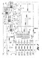
- Figure 3 is a simplified schematic and block diagram view showing a partitioning arrangement of a first, preferred ignition system embodiment according to the present invention having an exemplary ion sense integrated circuit.
- Figure 4 is a simplified schematic and block diagram view of a second ignition system embodiment according to the present invention.
- Figure 2 is a simplified perspective view of an ignition system 22 in accordance with the present invention.
- Figure 2 further illustrates a main control unit 24, a main multiconductor wiring harness 26, and a plurality of ignition coils 28 1 , 28 2 , 28 3 and 28 4 .
- Figure 2 also shows one or more inter-coil wiring harness connections designated 30, 32 and 34 and a plurality of spark plug access wells 36 in an internal combustion 38.
- Ignition system 22 is adapted for installation to conventional internal combustion engine 38.
- Internal combustion engine 38 may include a plurality of spark plug access wells 36, as noted above.
- the ignition system 22 is configured for installation by disposing the respective distal ends of each ignition coil 28 1 , 28 2 , 28 3 and 28 4 through the spark plug wells 36 onto a respective high-voltage terminal of the respective spark plug (not shown).
- the number of ignition coils will generally be equal to the number of spark plugs (and thus cylinders) in a conventional arrangement, although other variations are clearly possible ( e.g. , two, three, five, six, eight, ten, etc.).
- Each spark plug as known, may be retained by threaded engagement with the spark plug opening in a combustion cylinder in engine 38.
- Engine 38 may provide power for locomotion at the self-propelled vehicle, such as an automotive vehicle.
- control unit 24 may be configured to control the operation of each ignition coil.
- Control unit 24 may comprise a engine control unit (ECU) or the like containing electronics and other conventional hardware and software as eluded to above.
- ECU engine control unit
- control unit 24 may be configured to determine when charging of a particular coil is to commence for each cylinder, and for how long, and when spark events should occur relative to a crank shaft position, for example.
- Control unit 24 then generates electrical signals (e.g., one or more electronic spark timing (EST) signals) as may be required to implement an operating strategy as outlined above.
- electrical signals e.g., one or more electronic spark timing (EST) signals
- EST electronic spark timing
- control unit 24 may comprise a conventional apparatus known to those of ordinary skill in the art, and therefore will not be described in any further detail.
- Ignition coils 28 1 , 28 2 , 28 3 and 28 4 have a relatively slender configuration adapted for mounting directly above the spark plug - commonly referred to as a "pencil" coil.
- the improvements occasioned by the present invention involve modification of a first one of the ignition coils, for example, 28 1 , in a manner different from the modifications to the remainder of the ignition coils, for example 28 2 through 28 4 .
- the ignition coils 28 1 , 28 2 , 28 3 and 28 4 are in physically separate packages, connected by the wiring connections 30, 32 and 34.
- each ignition coil 28 i includes at least a primary winding, a secondary winding having a high voltage end configured for connection to a spark plug, and a magnetic circuit that includes at least a generally cylindrical, central main core, and an outer, annular side core. Both cores may be made from magnetically-permeable material.
- circuitry for example, complex control circuits such as ion sense systems
- the conventional art has taught including such circuitry (e.g., in the form of an integrated circuit) in each ignition coil.
- This arrangement results in a cost penalty for the overall system, and perhaps a decreased reliability (resulting from a numerically increased number of parts).
- the subject electronics are partitioned so that they are physically located in one ignition coil and configured to be shared with the remaining ignition coils.
- An ignition system for an internal combustion engine is thus provided where a first ignition coil, such as ignition coil 28 1 , has an electronic circuit associated therewith.
- One or more additional ignition coils such as ignition coils 28 2 , 28 3 and 28 4 , are coupled to the first ignition coil 28 1 .
- the electronic circuit that is located in the first ignition coil 28 1 is shared with the other ignition coils, so that, in-effect, such electronic circuit is responsive to the operation of the second, and further additional ignition coils (if any).
- the electronic circuit generally speaking, may be modified so that it can be shared with the other ignition coils.
- a single, four-channel IC may be provided in the main ignition coil 28 1 . Similar modifications may be made, depending on the nature of the electronic circuit.
- the inter-coil wiring connections are characterized by an element of flexibility in packaging, wherein in contrast a cassette ( i.e., a rigid housing) does not.
- Figure 3 and Figure 4 illustrate the broad aspects of the present invention where the electronic circuit comprises an ion sense integrated circuit (IC) and where a cassette cannot be packaged and thus individual coils are required.
- Figure 3 specifically shows a first embodiment of ignition system 22 where the first ignition coil 28 1 contains an electronic circuit (i.e., a multi-channel ion sense IC) configured to be shared with other ignition coils, as well as the main primary current driver for each ignition coil and the remaining support circuitry.
- Figure 4 illustrates an alternate embodiment where the electronic circuit (i.e., the multi-channel ion sense IC) is included in first ignition coil 28 1 , but where the other ignition coils in the ignition system each contain its own primary current driver device (e.g., an IGBT).
- the embodiment of Figure 4 is particularly suited to the situation where the packaging size or geometry precludes including all of the main, primary current driver devices in the first ignition coil package.
- ignition system 22 includes first ignition coil 28 1 having the shared electronic circuit, as well as one or more additional ignition coils 28 2 , 28 3 and 28 4 that are each coupled to the first ignition coil 28 1 .
- Figure 3 shows, in this regard, that ignition coil 28 1 includes a primary winding 40 1 , a secondary winding 42 1 , and a magnetic core 44 1 , as known.
- ignition coil 28 2 includes a corresponding primary winding 40 2 , a corresponding secondary winding 42 2 , and a corresponding magnetic core 44 2 .
- Ignition coil 28 3 includes a corresponding primary winding 40 3 , a corresponding secondary winding 42 3 , and a corresponding magnetic coil 44 3 .
- Ignition coil 28 4 includes a corresponding primary winding 40 4 , corresponding secondary winding 42 4, and a corresponding magnetic core 44 4.
- first ignition coil 28 1 in the illustrated embodiment, includes a primary current driver device, such as an insulated gate bipolar transistor (IGBT), designated 46 1.
- IGBT insulated gate bipolar transistor
- the driver devices 46 2 - 46 4 may also be IGBT devices.
- the primary current driver devices are provided for controlling respective primary currents in the ignition coils 28 1 through 28 4 .
- First ignition coil 28 1 also includes the above-described electronic circuit, which in the illustrated embodiment comprises a multi-channel, ion sense integrated circuit (IC) 48.
- the ion sense integrated circuit 48 is configured to sense a respective ion current through a respective spark plug to which each of the ignition coils is connected.
- the ion sense IC 48 includes a variety of inputs.
- the first group of signal lines are input/outputs with the control unit 24, and, in-effect are part of the main wiring harness 26.
- a first group of signal lines comprise electronic spark timing (EST) inputs for each of the plurality of ignition coils, respectively designated EST_1, EST_2, EST_3, and EST_4.
- EST electronic spark timing
- these signals control when charging of a respective ignition coil is to begin (i.e., EST_1 controls coil 28 1 , and so on), how long the charging persists as well as the timing of the spark itself ( i.e., when to discharge).
- the ion sense IC 48 also has a power source input signal, which may be derived from a vehicle battery, and which is designated B+ in the drawing. Ion sense IC 48 also has a ground input, designated GND.
- the CF/CQ signal line is an output from ion sense IC 48, and may comprise a pulse width modulated (PWM) signal indicative of a combustion quality sensed according to an ion sensing strategy.
- PWM pulse width modulated
- the KW/KI signal line may be a bi-directional signal line wherein a knock window (KW) signal is provided by control unit 24 to the ion sense IC 48 during a time interval when knock is expected to occur.
- Ion sense IC 48 may be configured to use the knock window signal (KN) provided thereto as a gating signal to control when the chip attempts to detect knock. That is, the ion sense IC 48 may be configured to process the ion current signal during the assertion of the knock window signal (KW) to determine and produce a knock intensity (KI) signal.
- the knock intensity (KI) signal may thereafter be transmitted over the KW/KI line back to the control unit 24, which may use such KI signal to make adjustments in its spark timing, fuel delivery, and the like to reduce or eliminate knock (according to known strategies).
- the second group of signal lines provided on ion sense IC 48 comprise input/output (I/O) lines to the remaining electronics located in the packaging for first ignition coil 28 1 .
- the signals GD_1, GD_2, GD_3, and GD_4 are outputs from chip 48 and define gate drive signals for respective primary current driver devices 46 1 - 46 4, respectively. Asserting the GD_1 signal, for example, commences the flow of primary current through switch 46 1 , while deasserting the GD_1 signal turns switch 46 1 off, thus causing a spark (as known).
- ion sense IC 48 may be configured as a "make" voltage bias ion sense system, for example as seen by reference to U.S. Patent No. 6,263,727, issued to Butler, et al. hereby incorporated by reference in its entirety.
- the ion sense control circuit preferably senses a primary current, among other things. The level of primary current may be sensed on the PC_SEN line.
- the signal lines IONIN_1, IONIN_2, IONIN_3, and IONIN_4 are provided for receiving ion current signals for the respective ignition coils. Each of these signals is representative of the ion current through the electrode cap of the respectively associated spark plug.
- the SC_SEN signal line is an input signal line for a secondary current indicative signal, which represents the level of secondary current through a respective one of the secondary windings of the ignition coils 28 1 through 28 4 .
- Ignition coil 28 1 further includes ion sense biasing circuitry 50 1 , 50 2 , 50 3 and 50 4 associated respectively with each of the four ignition coils shown in Figure 3.
- ion sense biasing circuitry 50 1 , 50 2 , 50 3 and 50 4 associated respectively with each of the four ignition coils shown in Figure 3.
- a relatively high voltage that occurs during the spark event may be used to reverse break down the zener diodes, which allow the capacitor located in parallel with the zener diode to be changed to substantially the same level as the reverse break down level (e.g., 100 volts).
- the charge on the respective capacitor may then subsequently be used as a biasing voltage to bias the spark plug for producing ion current, all is known to one of ordinary skill in the art.
- Figure 3 further shows the inter-coil wiring connections 30, 32, and 34.
- Wiring connection 30, 32 and 34 in the illustrated embodiment each comprise respective primary winding and secondary winding return leads.
- Wiring connections 30, 32 and 34 may comprise conventional metallic conductors, sized according to well known principals in the art (i.e., as to AWG, insulation, shielding, if any, etc.).
- the first ignition coil 28 1 contains a 4-channel ion sense integrated circuit 48, a variety of external components for the support of integrated circuit 48, and all of the primary current driver devices (e.g. the IGBTs) in the ignition system 22.
- the illustrated arrangement allows for a two-wire connection (i.e., inter-coil wiring connections 30, 32 and 34) between main ignition coil 28 1 and each of the remaining ignition coils.
- the cost of a 4-channel integrated circuit 48 is only slightly more than the cost of a single channel ion sense integrated circuit (not shown); however, for a single-channel ion sense integrated circuit, a total of four (4) of such integrated circuits would be required were each stand alone ignition coil in the illustrated embodiment to be so configured, thereby nearly quadrupling the cost.
- the foregoing partitioning approach for ignition systems with complex control circuits allows a fairly substantial reduction in the total electronics cost.
- the overall reliability is expected to be increased, since numerically fewer integrated circuits would be needed on an overall ignition system basis ( i.e., per engine).
- FIG 4 shows an alternate embodiment for an ignition system according to the present invention, designated ignition system 22a.
- the embodiment of Figure 4 is similar to the embodiment of Figure 3, except that each physically separate ignition coil (i.e., in its own separate package) contains its own primary current driver 46 1 through 46 4 .
- the ignition coils in ignition system 22a are designated 28 1a and 28 2a , 28 3a and 28 4a .
- the inter-coil wiring connections now each contain three conductors. One of the conductors remains the secondary winding return path. However, the other two conductors are now a respective gate drive signal connection for the primary driver, and a respective emitter lead ( i.e., a primary current return) connection.
Landscapes
- Engineering & Computer Science (AREA)
- Chemical & Material Sciences (AREA)
- Combustion & Propulsion (AREA)
- Mechanical Engineering (AREA)
- General Engineering & Computer Science (AREA)
- Ignition Installations For Internal Combustion Engines (AREA)
Applications Claiming Priority (2)
| Application Number | Priority Date | Filing Date | Title |
|---|---|---|---|
| US192834 | 2002-07-10 | ||
| US10/192,834 US20040007222A1 (en) | 2002-07-10 | 2002-07-10 | Electronics partitioning for ignition systems with control circuits |
Publications (1)
| Publication Number | Publication Date |
|---|---|
| EP1380751A2 true EP1380751A2 (de) | 2004-01-14 |
Family
ID=29735310
Family Applications (1)
| Application Number | Title | Priority Date | Filing Date |
|---|---|---|---|
| EP03076971A Withdrawn EP1380751A2 (de) | 2002-07-10 | 2003-06-25 | Aufteilung der Elektronik eines Zündsystems mit integrierten Steuerschaltungen |
Country Status (2)
| Country | Link |
|---|---|
| US (1) | US20040007222A1 (de) |
| EP (1) | EP1380751A2 (de) |
Families Citing this family (4)
| Publication number | Priority date | Publication date | Assignee | Title |
|---|---|---|---|---|
| JP4246228B2 (ja) * | 2006-10-20 | 2009-04-02 | 三菱電機株式会社 | 内燃機関点火装置 |
| US8547104B2 (en) * | 2010-03-01 | 2013-10-01 | Woodward, Inc. | Self power for ignition coil with integrated ion sense circuitry |
| JP6609927B2 (ja) * | 2014-04-10 | 2019-11-27 | 株式会社デンソー | 内燃機関用点火装置 |
| US9541022B2 (en) * | 2014-04-28 | 2017-01-10 | Caterpillar Inc. | Electronic control module with driver banks for engines |
Citations (1)
| Publication number | Priority date | Publication date | Assignee | Title |
|---|---|---|---|---|
| US4706639A (en) | 1986-12-04 | 1987-11-17 | General Motors Corporation | Integrated direct ignition module |
-
2002
- 2002-07-10 US US10/192,834 patent/US20040007222A1/en not_active Abandoned
-
2003
- 2003-06-25 EP EP03076971A patent/EP1380751A2/de not_active Withdrawn
Patent Citations (1)
| Publication number | Priority date | Publication date | Assignee | Title |
|---|---|---|---|---|
| US4706639A (en) | 1986-12-04 | 1987-11-17 | General Motors Corporation | Integrated direct ignition module |
Also Published As
| Publication number | Publication date |
|---|---|
| US20040007222A1 (en) | 2004-01-15 |
Similar Documents
| Publication | Publication Date | Title |
|---|---|---|
| US5534781A (en) | Combustion detection via ionization current sensing for a "coil-on-plug" ignition system | |
| US6557537B2 (en) | Ion current detection system and method for internal combustion engine | |
| US5758629A (en) | Electronic ignition system for internal combustion engines and method for controlling the system | |
| US6123057A (en) | Arrangement and process for communication between an ignition module and control unit in a combustion engine's ignition system | |
| JP2004316469A (ja) | 内燃機関用点火装置およびそのイグナイタ | |
| US5307786A (en) | Ignition apparatus for an internal combustion engine | |
| WO1997027400A1 (en) | Measuring circuit for sensing ionisation within a cylinder of a combustion engine | |
| JP3212601B2 (ja) | 信号検出装置 | |
| US5188088A (en) | Electronic ignition system for an internal combustion engine | |
| US20040007222A1 (en) | Electronics partitioning for ignition systems with control circuits | |
| US20050050948A1 (en) | Low cost circuit for IC engine diagnostics using ionization current signal | |
| US5216369A (en) | Ignition occurrence detecting device for use in an ignition apparatus | |
| US6216530B1 (en) | Combustion state detecting device for an internal combustion engine | |
| US6498490B2 (en) | Ion sense ignition bias circuit | |
| US5294888A (en) | Device for detecting misfire of an internal combustion engine by comparing voltage waveforms associated with ignition system | |
| EP0508804A1 (de) | Sekundärseitige Spannungswellenform-Detektorvorrichtung für Brennkraftmaschine | |
| EP0384436B1 (de) | Vorrichtung für die Zündungserkennung bei einer Zündungseinrichtung | |
| US8547104B2 (en) | Self power for ignition coil with integrated ion sense circuitry | |
| EP0665376B1 (de) | Zündaussetzererkennungsvorrichtung | |
| JP3831640B2 (ja) | 内燃機関点火装置 | |
| JPH04339175A (ja) | 火花点火機関の失火検出装置 | |
| US4469080A (en) | Ignition control bypass cable | |
| JP3831641B2 (ja) | 内燃機関点火装置 | |
| JP4127373B2 (ja) | 内燃機関のイオン電流検出装置 | |
| JP3283605B2 (ja) | イオン電流検出装置 |
Legal Events
| Date | Code | Title | Description |
|---|---|---|---|
| PUAI | Public reference made under article 153(3) epc to a published international application that has entered the european phase |
Free format text: ORIGINAL CODE: 0009012 |
|
| AK | Designated contracting states |
Kind code of ref document: A2 Designated state(s): AT BE BG CH CY CZ DE DK EE ES FI FR GB GR HU IE IT LI LU MC NL PT RO SE SI SK TR |
|
| AX | Request for extension of the european patent |
Extension state: AL LT LV MK |
|
| STAA | Information on the status of an ep patent application or granted ep patent |
Free format text: STATUS: THE APPLICATION IS DEEMED TO BE WITHDRAWN |
|
| 18D | Application deemed to be withdrawn |
Effective date: 20051231 |