EP1380725A2 - Anfertigungs- und Zusammenstellungsverfahren einer Kühleinrichtung innerhalb einer Schaufel für eine axialdurchströmte Gasturbine und mit einen solchen Verfahren hergestellte Schaufel - Google Patents
Anfertigungs- und Zusammenstellungsverfahren einer Kühleinrichtung innerhalb einer Schaufel für eine axialdurchströmte Gasturbine und mit einen solchen Verfahren hergestellte Schaufel Download PDFInfo
- Publication number
- EP1380725A2 EP1380725A2 EP03015872A EP03015872A EP1380725A2 EP 1380725 A2 EP1380725 A2 EP 1380725A2 EP 03015872 A EP03015872 A EP 03015872A EP 03015872 A EP03015872 A EP 03015872A EP 1380725 A2 EP1380725 A2 EP 1380725A2
- Authority
- EP
- European Patent Office
- Prior art keywords
- blade
- chamber
- openings
- insert
- forcing
- Prior art date
- Legal status (The legal status is an assumption and is not a legal conclusion. Google has not performed a legal analysis and makes no representation as to the accuracy of the status listed.)
- Withdrawn
Links
Images


Classifications
-
- F—MECHANICAL ENGINEERING; LIGHTING; HEATING; WEAPONS; BLASTING
- F01—MACHINES OR ENGINES IN GENERAL; ENGINE PLANTS IN GENERAL; STEAM ENGINES
- F01D—NON-POSITIVE DISPLACEMENT MACHINES OR ENGINES, e.g. STEAM TURBINES
- F01D17/00—Regulating or controlling by varying flow
- F01D17/10—Final actuators
- F01D17/12—Final actuators arranged in stator parts
- F01D17/14—Final actuators arranged in stator parts varying effective cross-sectional area of nozzles or guide conduits
- F01D17/16—Final actuators arranged in stator parts varying effective cross-sectional area of nozzles or guide conduits by means of nozzle vanes
- F01D17/162—Final actuators arranged in stator parts varying effective cross-sectional area of nozzles or guide conduits by means of nozzle vanes for axial flow, i.e. the vanes turning around axes which are essentially perpendicular to the rotor centre line
-
- F—MECHANICAL ENGINEERING; LIGHTING; HEATING; WEAPONS; BLASTING
- F01—MACHINES OR ENGINES IN GENERAL; ENGINE PLANTS IN GENERAL; STEAM ENGINES
- F01D—NON-POSITIVE DISPLACEMENT MACHINES OR ENGINES, e.g. STEAM TURBINES
- F01D5/00—Blades; Blade-carrying members; Heating, heat-insulating, cooling or antivibration means on the blades or the members
- F01D5/12—Blades
- F01D5/14—Form or construction
- F01D5/18—Hollow blades, i.e. blades with cooling or heating channels or cavities; Heating, heat-insulating or cooling means on blades
- F01D5/187—Convection cooling
- F01D5/188—Convection cooling with an insert in the blade cavity to guide the cooling fluid, e.g. forming a separation wall
- F01D5/189—Convection cooling with an insert in the blade cavity to guide the cooling fluid, e.g. forming a separation wall the insert having a tubular cross-section, e.g. airfoil shape
-
- F—MECHANICAL ENGINEERING; LIGHTING; HEATING; WEAPONS; BLASTING
- F05—INDEXING SCHEMES RELATING TO ENGINES OR PUMPS IN VARIOUS SUBCLASSES OF CLASSES F01-F04
- F05D—INDEXING SCHEME FOR ASPECTS RELATING TO NON-POSITIVE-DISPLACEMENT MACHINES OR ENGINES, GAS-TURBINES OR JET-PROPULSION PLANTS
- F05D2260/00—Function
- F05D2260/20—Heat transfer, e.g. cooling
- F05D2260/201—Heat transfer, e.g. cooling by impingement of a fluid
-
- Y—GENERAL TAGGING OF NEW TECHNOLOGICAL DEVELOPMENTS; GENERAL TAGGING OF CROSS-SECTIONAL TECHNOLOGIES SPANNING OVER SEVERAL SECTIONS OF THE IPC; TECHNICAL SUBJECTS COVERED BY FORMER USPC CROSS-REFERENCE ART COLLECTIONS [XRACs] AND DIGESTS
- Y02—TECHNOLOGIES OR APPLICATIONS FOR MITIGATION OR ADAPTATION AGAINST CLIMATE CHANGE
- Y02T—CLIMATE CHANGE MITIGATION TECHNOLOGIES RELATED TO TRANSPORTATION
- Y02T50/00—Aeronautics or air transport
- Y02T50/60—Efficient propulsion technologies, e.g. for aircraft
Definitions
- the present invention relates to a method of producing and assembling a cooling device inside an axial-flow gas turbine blade, and in particular an adjustable-angle blade of a variable-geometry gas turbine stator, to which the following description refers purely by way of example.
- the airfoil profile of such a blade is hinged to the annular platforms defining the gas conduit in the stator, and comprises a tail portion connected in sliding manner to the platforms.
- a method of producing and assembling a cooling device inside a blade of an axial-flow gas turbine comprising an airfoil profile having an inner surface defining a chamber, and two connecting end portions located on opposite sides of said airfoil profile for connection to respective supporting structures forming part of said turbine, and having respective openings for the passage of a cooling fluid and which come out inside said chamber; the method comprising the steps of forming an insert having a number of holes; and positioning said insert inside said chamber so as to face said inner surface and direct a relative stream of said cooling fluid through each said hole on to said inner surface; characterized in that said insert is formed by producing a first and at least a second body separate from each other and each of a size approximating but no larger than that of at least one of said openings; and in that positioning said insert inside said chamber comprises the step of inserting said first and said second body successively through said openings.
- the present invention also relates to an axial-flow gas turbine blade.
- a blade for an axial-flow gas turbine comprising an airfoil profile having an inner surface defining a chamber; two connecting end portions located on opposite sides of said airfoil profile for connection to respective structures forming part of said turbine, and having respective openings for the passage of a cooling fluid and which come out inside said chamber; and a cooling device comprising an insert having a number of holes and positioned inside said chamber so as to face said inner surface and direct a relative stream of said cooling fluid through each said hole on to said inner surface; characterized in that said insert comprises a first and at least a second body separate from each other and each of a size approximating but no larger than that of at least one of said openings, so as to be insertable through the openings.
- Number 1 in the accompanying drawings indicates a blade for a stator (not shown) of an aircraft variable-geometry axial-flow gas turbine (not shown).
- Blade 1 comprises an airfoil profile 2 housed, in use, inside an annular gas conduit of the turbine, and in turn comprising a front portion 4 hinged about an axis 5 and by respective opposite pins 6a, 6b to two annular platforms (not shown) of the stator defining the conduit.
- Pins 6a, 6b are coaxial, are formed in one piece with portion 4, and define respective circular openings 7a, 7b, which are coaxial along axis 5, come out inside a chamber 8 defined by an inner surface 9 of profile 2, are relatively small in diameter with respect to the size of chamber 8, and, in use, permit the passage of a stream of cooling air.
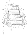
- Profile 2 also comprises a tail portion 11, in turn comprising a high-pressure wall 12, a low-pressure wall 13, and two walls 14 located on opposite axial sides of walls 12, 13, and connected in sliding manner, in use, to said platforms (Figure 3).
- Blade 1 also comprises a cooling device 15, in turn comprising an assembly 16 of four separate bodies 17, 18, 19, 20 housed inside chamber 8.
- Each body 17, 18, 19, 20 comprises a relative portion of a lateral wall 21 ( Figure 3), which faces surface 9, extends along the whole of surface 9, and has a number of holes 22 (shown schematically) through which respective cooling air jets flow from the centre of chamber 8 on to surface 9.
- Bodies 17, 18, 19, 20 are elongated parallel to axis 5, are aligned with one another in a direction A radial with respect to axis 5, and are each of a size, crosswise to axis 5, approximating but no larger than the diameter of at least one of openings 7a, 7b, so as to be insertable axially through openings 7a, 7b.
- Bodies 17, 18, 20 are box- or shell-shaped, and rest on relative inner ribs 23 (shown partly) of profile 2, so as to be kept detached from surface 9.
- body 17 is located inside chamber 8 at the end of portion 11, is substantially wedge-shaped, defines an inner cavity 24, is interposed between walls 14 ( Figure 3), and is forced between walls 12, 13 in direction A towards the trailing edge of portion 11.
- Body 18 is interposed between bodies 17 and 19, rests axially on walls 14, rests on body 17 in direction A, and defines an inner cavity 25 communicating with cavity 24 through two openings 26a, 26b formed in front of each other in respective bodies 17, 18 ( Figure 2).
- Body 20 is located inside chamber 8 close to the leading edge of portion 4, has a substantially half-moon-shaped cross section, defines an inner cavity 28, and rests axially on an inner shoulder 29 of pin 6a ( Figure 2).
- body 19 is tubular, and is bounded by a truncated-cone-shaped outer surface 31 resting, in direction A, on two concave surfaces 32, 33 complementary to surface 31 and bounding respective bodies 18, 20.
- Body 19 defines an inner channel 34 connecting openings 7a, 7b, and in turn communicating with cavity 25 through two openings 35a, 35b formed in front of each other in respective bodies 18, 19, and with cavity 28 through two openings 37a, 37b formed in front of each other in respective bodies 20, 19.
- Body 19 comprises two opposite end portions 40, 41.
- Portion 40 is housed in opening 7a, rests on the inner surface 42 of pin 6a, and is connected integrally to surface 42 by a brazed joint 42a not shown in detail.
- Portion 41 is connected to pin 6b with the interposition of an annular retaining member 43, which forms part of device 15, is housed in opening 7b, and comprises a cylindrical portion 44 connected integrally, preferably brazed, to pin 6b in a manner not shown in detail.
- Member 43 also comprises a tab 46, which projects from portion 44, perpendicularly to axis 5, rests axially on portion 41, and is connected integrally to portion 41 by a brazed joint 46a not shown in detail.
- device 15 also comprises two C-section spacers 48, 49, which are interposed axially between tab 46 and respective bodies 18, 20, and are deformed elastically to force bodies 18, 20 elastically and axially towards pin 6a.
- Assembly 16 defines an insert or plate, which is externally substantially a negative of the shape of chamber 8, and can be dismantled, i.e. into bodies 17, 18, 19, 20 smaller than, and therefore insertable successively through, openings 7a, 7b.
- body 17 is first inserted through opening 7b and pushed to the end of the chamber towards the trailing edge of portion 11.
- Body 18 is then inserted through opening 7b into chamber 8 and positioned adjacent to body 17 in direction A; body 20 is inserted through opening 7a to rest on portion 4 in direction A; and finally, body 19 is inserted, and, as it moves along axis 5, forces bodies 17, 18, 20 in direction A by virtue of the taper of surface 31.
- portion 40 is brazed to pin 6a, and portion 41 is fixed to pin 6b by attaching member 43 and interposing spacers 48, 49 between member 43 and bodies 18, 20.
- the method described therefore provides for inserting a cooling insert or plate easily inside profile 2, even when the openings 7a, 7b in the connecting end portions of blade 1 are relatively small, by the insert or plate being dismantled into a number of separate parts (four in the example described).
- Device 15 is also relatively easy to assemble and fix to profile 2, by only body 19 being connected integrally to pins 6a, 6b, and by bodies 18, 19, 20 being locked automatically inside chamber 8 by body 19 and member 43.
- dismantling the insert or plate into at least two separate successively inserted bodies also applies advantageously to other types of blades having relatively small access openings with respect to the transverse dimensions of the inner chamber of the airfoil profile.
Landscapes
- Engineering & Computer Science (AREA)
- Mechanical Engineering (AREA)
- General Engineering & Computer Science (AREA)
- Turbine Rotor Nozzle Sealing (AREA)
Applications Claiming Priority (2)
| Application Number | Priority Date | Filing Date | Title |
|---|---|---|---|
| IT2002TO000607A ITTO20020607A1 (it) | 2002-07-12 | 2002-07-12 | Metodo per la realizzazione ed il montaggio di un dispositivo di raffreddamento in una paletta di una turbina assiale a gas e paletta per un |
| ITTO20020607 | 2002-07-12 |
Publications (2)
| Publication Number | Publication Date |
|---|---|
| EP1380725A2 true EP1380725A2 (de) | 2004-01-14 |
| EP1380725A3 EP1380725A3 (de) | 2004-09-15 |
Family
ID=11459488
Family Applications (1)
| Application Number | Title | Priority Date | Filing Date |
|---|---|---|---|
| EP03015872A Withdrawn EP1380725A3 (de) | 2002-07-12 | 2003-07-11 | Anfertigungs- und Zusammenstellungsverfahren einer Kühleinrichtung innerhalb einer Schaufel für eine axialdurchströmte Gasturbine und mit einen solchen Verfahren hergestellte Schaufel |
Country Status (4)
| Country | Link |
|---|---|
| US (1) | US20040109763A1 (de) |
| EP (1) | EP1380725A3 (de) |
| CA (1) | CA2435070A1 (de) |
| IT (1) | ITTO20020607A1 (de) |
Cited By (5)
| Publication number | Priority date | Publication date | Assignee | Title |
|---|---|---|---|---|
| EP2469029A1 (de) * | 2010-12-22 | 2012-06-27 | Siemens Aktiengesellschaft | Prallkühlung von Gasturbinenschaufeln |
| EP2540969A1 (de) | 2011-06-27 | 2013-01-02 | Siemens Aktiengesellschaft | Aufprallkühlung von Turbinenschaufeln oder -flügeln |
| EP2573325A1 (de) | 2011-09-23 | 2013-03-27 | Siemens Aktiengesellschaft | Aufprallkühlung von Turbinenschaufeln oder -flügeln |
| EP2860348A1 (de) * | 2013-10-08 | 2015-04-15 | Siemens Aktiengesellschaft | Einsatz für eine Turbinenschaufel aus mehreren Bauteilen und zugehöriges Verfahren |
| EP3323995A3 (de) * | 2016-11-17 | 2018-07-25 | United Technologies Corporation | Tragfläche mit seitlich einsetzbarem leitblech |
Families Citing this family (3)
| Publication number | Priority date | Publication date | Assignee | Title |
|---|---|---|---|---|
| ITTO20020699A1 (it) * | 2002-08-06 | 2004-02-07 | Fiatavio Spa | Paletta per lo statore di una turbina a geometria variabile, |
| US10422244B2 (en) | 2015-03-16 | 2019-09-24 | General Electric Company | System for cooling a turbine shroud |
| JP6651378B2 (ja) * | 2016-02-22 | 2020-02-19 | 三菱日立パワーシステムズ株式会社 | インサート組品、翼、ガスタービン、および、翼の製造方法 |
Citations (3)
| Publication number | Priority date | Publication date | Assignee | Title |
|---|---|---|---|---|
| US4413949A (en) * | 1974-10-17 | 1983-11-08 | Rolls Royce (1971) Limited | Rotor blade for gas turbine engines |
| US4798515A (en) * | 1986-05-19 | 1989-01-17 | The United States Of America As Represented By The Secretary Of The Air Force | Variable nozzle area turbine vane cooling |
| EP1219784A2 (de) * | 2000-12-28 | 2002-07-03 | General Electric Company | Einrichtung zur örtlichen Kühlung der Wände von Gasturbinenleitapparaten |
Family Cites Families (2)
| Publication number | Priority date | Publication date | Assignee | Title |
|---|---|---|---|---|
| SE395934B (sv) * | 1976-01-19 | 1977-08-29 | Stal Laval Turbin Ab | Kyld-ihalig ledskovel for gasturbin |
| US4257734A (en) * | 1978-03-22 | 1981-03-24 | Rolls-Royce Limited | Guide vanes for gas turbine engines |
-
2002
- 2002-07-12 IT IT2002TO000607A patent/ITTO20020607A1/it unknown
-
2003
- 2003-07-11 US US10/604,337 patent/US20040109763A1/en not_active Abandoned
- 2003-07-11 EP EP03015872A patent/EP1380725A3/de not_active Withdrawn
- 2003-07-11 CA CA002435070A patent/CA2435070A1/en not_active Abandoned
Patent Citations (3)
| Publication number | Priority date | Publication date | Assignee | Title |
|---|---|---|---|---|
| US4413949A (en) * | 1974-10-17 | 1983-11-08 | Rolls Royce (1971) Limited | Rotor blade for gas turbine engines |
| US4798515A (en) * | 1986-05-19 | 1989-01-17 | The United States Of America As Represented By The Secretary Of The Air Force | Variable nozzle area turbine vane cooling |
| EP1219784A2 (de) * | 2000-12-28 | 2002-07-03 | General Electric Company | Einrichtung zur örtlichen Kühlung der Wände von Gasturbinenleitapparaten |
Cited By (13)
| Publication number | Priority date | Publication date | Assignee | Title |
|---|---|---|---|---|
| US9500087B2 (en) | 2010-12-22 | 2016-11-22 | Siemens Aktiengesellschaft | Impingement cooling of gas turbine blades or vanes |
| WO2012084454A1 (en) * | 2010-12-22 | 2012-06-28 | Siemens Aktiengesellschaft | Impingement cooling of gas turbine blades or vanes |
| RU2646663C2 (ru) * | 2010-12-22 | 2018-03-06 | Сименс Акциенгезелльшафт | Инжекционное охлаждение роторных лопаток и статорных лопаток газовой турбины |
| EP2469029A1 (de) * | 2010-12-22 | 2012-06-27 | Siemens Aktiengesellschaft | Prallkühlung von Gasturbinenschaufeln |
| EP2540969A1 (de) | 2011-06-27 | 2013-01-02 | Siemens Aktiengesellschaft | Aufprallkühlung von Turbinenschaufeln oder -flügeln |
| WO2013000691A1 (en) | 2011-06-27 | 2013-01-03 | Siemens Aktiengesellschaft | Impingement cooling of turbine blades or vanes |
| US9650899B2 (en) | 2011-06-27 | 2017-05-16 | Siemens Aktiengesellschaft | Impingement cooling of turbine blades or vanes |
| US9777581B2 (en) | 2011-09-23 | 2017-10-03 | Siemens Aktiengesellschaft | Impingement cooling of turbine blades or vanes |
| WO2013041361A1 (en) | 2011-09-23 | 2013-03-28 | Siemens Aktiengesellschaft | Impingement cooling of turbine blades or vanes |
| EP2573325A1 (de) | 2011-09-23 | 2013-03-27 | Siemens Aktiengesellschaft | Aufprallkühlung von Turbinenschaufeln oder -flügeln |
| EP2860348A1 (de) * | 2013-10-08 | 2015-04-15 | Siemens Aktiengesellschaft | Einsatz für eine Turbinenschaufel aus mehreren Bauteilen und zugehöriges Verfahren |
| EP3323995A3 (de) * | 2016-11-17 | 2018-07-25 | United Technologies Corporation | Tragfläche mit seitlich einsetzbarem leitblech |
| US10502070B2 (en) | 2016-11-17 | 2019-12-10 | United Technologies Corporation | Airfoil with laterally insertable baffle |
Also Published As
| Publication number | Publication date |
|---|---|
| CA2435070A1 (en) | 2004-01-12 |
| US20040109763A1 (en) | 2004-06-10 |
| ITTO20020607A1 (it) | 2004-01-12 |
| ITTO20020607A0 (it) | 2002-07-12 |
| EP1380725A3 (de) | 2004-09-15 |
Similar Documents
| Publication | Publication Date | Title |
|---|---|---|
| EP1764481A2 (de) | Statorschaufel mit keramischem Schaufelblatt und metallischen Plattformen | |
| EP2758634B1 (de) | Prallkühlung von turbinenschaufeln | |
| CN108457705B (zh) | 用于对接陶瓷基复合材料构件至金属构件的方法和系统 | |
| EP3034799B1 (de) | Beschaufelung für eine Strömungsmaschine | |
| CN102132011B (zh) | 涡轮发动机的轻质固定翼片组件和包括至少一个这种固定翼片组件的涡轮发动机 | |
| EP1760266A2 (de) | Herstellung einer Leitschaufel einer Turbine | |
| EP2048328A2 (de) | Rückhaltefunktion für eine Dichteinrichtung und Montageverfahren dafür | |
| EP1380725A2 (de) | Anfertigungs- und Zusammenstellungsverfahren einer Kühleinrichtung innerhalb einer Schaufel für eine axialdurchströmte Gasturbine und mit einen solchen Verfahren hergestellte Schaufel | |
| CN102906375A (zh) | 用于轴流式涡轮机的叶片的固定装置及其制造方法 | |
| JP2009121460A (ja) | 取付け部品を覆瓦状に配置することによる径方向アームの円形フェルールへの接続 | |
| US9500087B2 (en) | Impingement cooling of gas turbine blades or vanes | |
| US6568692B2 (en) | Low stress seal | |
| US6913440B2 (en) | Variable-geometry turbine stator blade, particularly for aircraft engines | |
| EP1978265A1 (de) | Wartungsverfahren für eine Gasturbine und Gasturbineneinheit | |
| JP2004101174A (ja) | ガスタービンエンジンの複式環状燃焼器用の組立てカウルとその製作方法 | |
| US20140161590A1 (en) | Cover device, integrally bladed main rotor body, method and turbomachine | |
| EP2723989B1 (de) | Prallkühlung von turbinenlaufschaufeln oder -leitschaufeln | |
| US20190203604A1 (en) | Staking tool assembly | |
| US10767503B2 (en) | Stator assembly with retention clip for gas turbine engine | |
| US6719527B2 (en) | Tip treatment bar components | |
| US7806655B2 (en) | Method and apparatus for assembling blade shims | |
| JP2000297605A (ja) | 流体機械に於ける動翼の固定装置 | |
| JPH0771204A (ja) | 軸流機械のロータ構造体 |
Legal Events
| Date | Code | Title | Description |
|---|---|---|---|
| PUAI | Public reference made under article 153(3) epc to a published international application that has entered the european phase |
Free format text: ORIGINAL CODE: 0009012 |
|
| AK | Designated contracting states |
Kind code of ref document: A2 Designated state(s): AT BE BG CH CY CZ DE DK EE ES FI FR GB GR HU IE IT LI LU MC NL PT RO SE SI SK TR |
|
| AX | Request for extension of the european patent |
Extension state: AL LT LV MK |
|
| PUAL | Search report despatched |
Free format text: ORIGINAL CODE: 0009013 |
|
| AK | Designated contracting states |
Kind code of ref document: A3 Designated state(s): AT BE BG CH CY CZ DE DK EE ES FI FR GB GR HU IE IT LI LU MC NL PT RO SE SI SK TR |
|
| AX | Request for extension of the european patent |
Extension state: AL LT LV MK |
|
| AKX | Designation fees paid |
Designated state(s): AT BE BG CH CY CZ DE DK EE ES FI FR GB GR HU IE IT LI LU MC NL PT RO SE SI SK TR |
|
| STAA | Information on the status of an ep patent application or granted ep patent |
Free format text: STATUS: THE APPLICATION IS DEEMED TO BE WITHDRAWN |
|
| 18D | Application deemed to be withdrawn |
Effective date: 20050316 |