EP1380379A2 - Anordnung und Verfahren zur Regelung der Nahtlage eines laserstrahlgefügten Profils - Google Patents
Anordnung und Verfahren zur Regelung der Nahtlage eines laserstrahlgefügten Profils Download PDFInfo
- Publication number
- EP1380379A2 EP1380379A2 EP03008516A EP03008516A EP1380379A2 EP 1380379 A2 EP1380379 A2 EP 1380379A2 EP 03008516 A EP03008516 A EP 03008516A EP 03008516 A EP03008516 A EP 03008516A EP 1380379 A2 EP1380379 A2 EP 1380379A2
- Authority
- EP
- European Patent Office
- Prior art keywords
- seam
- information
- laser
- component
- control device
- Prior art date
- Legal status (The legal status is an assumption and is not a legal conclusion. Google has not performed a legal analysis and makes no representation as to the accuracy of the status listed.)
- Granted
Links
Images


Classifications
-
- B—PERFORMING OPERATIONS; TRANSPORTING
- B23—MACHINE TOOLS; METAL-WORKING NOT OTHERWISE PROVIDED FOR
- B23K—SOLDERING OR UNSOLDERING; WELDING; CLADDING OR PLATING BY SOLDERING OR WELDING; CUTTING BY APPLYING HEAT LOCALLY, e.g. FLAME CUTTING; WORKING BY LASER BEAM
- B23K26/00—Working by laser beam, e.g. welding, cutting or boring
- B23K26/02—Positioning or observing the workpiece, e.g. with respect to the point of impact; Aligning, aiming or focusing the laser beam
- B23K26/04—Automatically aligning, aiming or focusing the laser beam, e.g. using the back-scattered light
-
- B—PERFORMING OPERATIONS; TRANSPORTING
- B23—MACHINE TOOLS; METAL-WORKING NOT OTHERWISE PROVIDED FOR
- B23K—SOLDERING OR UNSOLDERING; WELDING; CLADDING OR PLATING BY SOLDERING OR WELDING; CUTTING BY APPLYING HEAT LOCALLY, e.g. FLAME CUTTING; WORKING BY LASER BEAM
- B23K26/00—Working by laser beam, e.g. welding, cutting or boring
- B23K26/20—Bonding
- B23K26/21—Bonding by welding
- B23K26/24—Seam welding
- B23K26/242—Fillet welding, i.e. involving a weld of substantially triangular cross section joining two parts
Definitions
- the invention relates to an arrangement and a method for regulating the seam position of a Laser beam-joined profile according to the preamble of claims 1 and 13.
- the seam flank angle ⁇ is used in the laser welding of welded parts (e.g. a stringer-skin arrangement) regarded as an essential output variable, its influence on the qualitative Execution of a laser weld on the finished welding part is known per se. His rating will be traditionally carried out only after the fully drawn weld has been carried out. Solutions that have a direct influence on the welding process, the one offered Change in the seam flank angle ⁇ is realized, exercised to a qualitatively acceptable Achieving a weld is not known. Welded parts are mainly considered, at for example the stringer standing vertically on the skin, the specialist circles also as Describe "smooth sheet metal shell" is positioned.
- the seam flank angle ⁇ results from the position of the laser beam and its position relative to the welding joint, for example the skin stringer joint.
- the seam flank angle ⁇ is accordingly between the skin and the surface of the Weld seam, its position - with a preliminary look at the attached Fig. 3 - more clearly becomes.
- the seam position and, in correlation, the expected seam flank angle ⁇ of the finished one The weld seam is influenced before the welding process begins.
- the position of the laser beam is fixed relative to the welding joint of the parts (skin stringer joint) specified before the laser welding is carried out.
- the position of the laser beam is fixed relative to the welding joint of the parts (skin stringer joint) specified before the laser welding is carried out.
- the angle at which the laser beams hit the outer surface of the workpiece and the seam position influenced is regulated depending on the measurement result of a measuring instrument [cf. DE 42 16 643 A1; Figure 7 in connection with column 9, lines 30 ff.].
- a measuring instrument cf. DE 42 16 643 A1; Figure 7 in connection with column 9, lines 30 ff.].
- a seam layer component for changing the seam layer
- one Laser welding process component with two integrated laser welding sources and a seam position control device built up.
- Sensor device for detecting characteristic quantities of the laser weld seam which, especially in the case of the sensor, following the one moving at the welding speed Laser welding sources is arranged [cf. DE 42 16 643 A1; Claim 12].
- the invention is therefore based on the object of an arrangement and a method for Show control of the seam position of a laser beam-joined profile with which the position and / or the position of a laser welding source is so influenced during the welding process that through controlled influence on the seam position and the seam flank angle ⁇ of the generated Weld whose surface geometry is improved.
- the aim is that with the Already slight fluctuations in the seam flank angle ⁇ can be compensated for permissible tolerance values of the seam flank angle ⁇ are implemented.
- the rewelding of the Weld seams should be avoided entirely.
- a smooth sheet metal shell 10 is used as a profile to be connected to a joining partner by laser beam welding, and refers to a stringer 11, which is used as a joining partner, by laser welding seams 13, 131 can be combined to form a welded part.
- a stringer 11 which is used as a joining partner
- laser welding seams 13, 131 can be combined to form a welded part.
- One so joined by laser beam welding stringer-reinforced smooth sheet metal shell 10 is increasingly used, for example, in aircraft construction find an improvement in weld quality and a reduction in reject rates with laser beam welding and the saving of additional effort through time-consuming Re-welding is subject to constant observation.
- Laser-beam-joined profiles (a stringer-reinforced smooth sheet metal shell) become these disadvantages switched off.
- Fig. 1 the block diagram of the arrangement for controlling the seam position NL of the stringer stiffened Smooth sheet metal shell 10 (a stringer-stiffened skin field) presented which the seam layer NL of the laser weld seams 13, 131, with which the parts according to FIG. 3 (stringer 11, smooth sheet metal shell 10) connected at the edge of the weld joint 12 (the skin stringer joint), regulates and thus in correlation the realization of the seam flank angle ⁇ of the laser weld seams 13, 131 (within the permitted tolerance values).
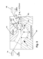
- Fig. 3 is a smooth sheet metal shell 10 and a stringer 11, which is perpendicular standing (ie: standing at a right angle) is positioned on the smooth sheet metal shell 10.
- the end face of the stringer 11 abuts the surface of the smooth sheet metal shell 10, thereby a weld joint 12 is formed on the contact surfaces of these parts.
- the stringer 11 relates to a Angle profile, which (in aircraft construction) for additional, locally limited stiffening of the Smooth sheet metal shell 10 is used.
- the smooth sheet metal shell 10 relates to a skin field (an outer skin of an aircraft), which (the) with a welded stringer profile (due to occurring pressure and / or shear loads on the smooth sheet metal shell 10) is stiffened.
- a laser welding source 14, 15 is in each case on the left and right side of the Stringer cross section arranged, which to realize the intended weld connection of the two parts emits a rectilinear laser beam 16, 17 during the welding process, which is directed towards the edge of the weld joint 12 of the two parts.
- a first Laser welding source 14 which is arranged on the left side of the Stringer cross section, with a first Laser beam 16, which radiates in the direction of a first rectilinear laser beam direction axis LSAR1, in Realize a first laser weld seam 13 in the area of the weld joint 12, its light energy content penetrates to a lower region of the laser weld seam 13 (seam root), at which none Melting of the metal material will take place more.
- a second laser welding source 15 which is arranged on the right side of the Stringer cross section, with a second laser beam 17, which is in the direction of a second rectilinear laser beam direction axis LSAR2 radiates in the area of the weld joint 12 a second laser weld 131 with the mentioned Realize effects.
- the penetration depth of the two laser beams 16, 17 is at a (predefined) Welding point SP ends, the welding effect at an upper area of the concerned Insert laser weld 13, 131 and will end at the root of the seam.
- the position of one (the relevant laser welding sources 14, 15 integrated) laser beam head, from which the individual laser beam 16, 17 emerges into the (free) space can be changed, one will (with the arrangement according to FIG. 1) a regulated correction of the position of the two laser steel sources 14, 15 by spatially changing their starting position in Change the axis direction in 3-dimensional space. This also makes the Angle of incidence ⁇ of the individual laser beam 16, 17 and its entry position in the marginal side The area of the weld joint 12 changed in favor of the change in the seam flank angle ⁇ .
- the distance AS is determined by a laser beam entry point LEP through which the individual laser beam 16, 17 penetrate into the non-laser-welded stringer 11 at a certain entry angle ⁇ and a weld butt intersection SSP through which the aforementioned weld butt tangent SST will occur, narrowed down. If now on the upper area of the individual laser weld seam 13, 131 a weld tangent SNT is created, the latter and the aforementioned weld butt tangent SST include the so-called seam flank angle ⁇ , the location of these two Tangents determined with the help of trigonometric functions or by calculating the radian measure leaves.
- the angle of incidence ⁇ mentioned is similar due to the detection the position of the individual laser beam direction axis LSRA1, LSRA2 and one parallel to Surface area of the smooth sheet metal shell 10 extending direction axis RA with the help trigonometric functions or by calculating the radians, the Axis position of the directional axis RA (quite) with that of the weld joint tangent SST will match.
- the aim is that the regulated change in the angle of incidence ⁇ of the individual Laser beam 16, 17 under practical conditions a seam flank angle ⁇ welding technology is implemented, the angular range between 40 ° and 50 ° will tolerate, practically one Seam position NL of about plus 0.5 mm is aimed for.
- an arrangement for regulating the seam position NL of a stringer-stiffened smooth sheet metal shell 10 is presented, which consists of several information technology, serial (in a control loop) connected system components and an integrated seam position control device 3.
- the system components relate to a seam layer component 1 for changing the seam layer NL and a laser welding process component 2 with two integrated laser welding sources 14, 15 for realizing the individual laser welding seam (13, 131), which are connected in series via information lines.
- the seam position control device 3 is implemented with a controller which is an electronic one-way controller designed as a proportional controller (P controller).
- P controller proportional controller
- a sensor device 4 is integrated into the arrangement, which is attached directly to or near the laser welding process component 2.
- the sensor device 4 comprises two sensor components 41, 42, which are positioned on the left and right sides of the Stringer cross section (according to the model in FIG. 3).
- Optical sensor components 41, 42 are used which, for example, have a light section sensor.
- the sensor device 4 is fastened in such a way that the sensor components 41, 42 are arranged in parallel with the laser welding sources 14, 15 moving horizontally at the welding speed.
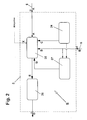
- the seam position control device 3 is internally equipped with a circuit S, which is shown in FIG. 2 is shown.
- the circuit S comprises several circuit components that are functionally connected are.
- the circuit S is - due to the functional linkage of the individual Circuit components - capable of comparing information during the welding process (continuously) supplied (external to the circuit) sensor information (s) A with a Convert nominal size information B of the seam flank angle ⁇ . Then the Comparison result generated a control variable D for the change in the seam flank angle ⁇ , the provided at the output 31 of the seam position control device 3 and the seam position component 1 Change in the seam position NL is supplied.
- the circuit S comprises a comparison component 35, a memory component 34, a Converter component 36 and a (optionally arranged) threshold component 37.
- the latter is of the circuit S mainly for the sake of reliably providing setpoint information of the flank angle ⁇ integrated with the sensor information A (as Actual size information of the seam flank angle ⁇ ) is compared, its optional use will become clearer below.
- Setpoint size information C can be called, but still a seam flank angle ⁇ with the required To achieve tolerance values.
- the comparison component 35 is on the input side with the mentioned first input 32 of the seam position control device 3 connected, via which the sensor information A is sent to it.
- a second input 33 of the seam position control device 3 is an external one Information line 5 connected, which is also another input of the Comparative component 35 is switched on. Via this external information line 5 the Comparison component 35 (in the normal case) a setpoint information fed in externally to the circuit B of the seam flank angle ⁇ .
- the Comparison component 35 (in the normal case) a setpoint information fed in externally to the circuit B of the seam flank angle ⁇ .
- the threshold component 37 which enables is, the correct information content of the setpoint information B using a Ascertaining the information technology threshold value will, if it is correctly determined Enable (initiate) direct information path via the external information line 5.
- the threshold value component 37 becomes less than an information technology Threshold value, a detected malfunction or a lack of setpoint information B signals via one of the comparison component 35 connected on the input side Connection transmit a threshold information Sl, which the comparison component 35 the Failure of the setpoint information B signals.
- the comparison component 35 is thereupon saved (fixed request the specified) target size information C. If one of the two setpoint information B, C of the comparison component 35 is available, the latter will make a comparison of its during the Welding process supplied sensor information (s) A with the corresponding target size information Make B, C.
- the result of the target-actual comparison is determined in a Comparison result information E summarized that the comparison component 35 via one of the Transducer component 36 connected connection the latter transmitted.
- the converter component 36 the comparison result information E obtained is then converted into a controlled variable D of the Generate seam flank angle ⁇ , which can be called up at the output 31 of the seam position control device 3.
- the output 31 is connected to the converter component 36 on the output side.
- the circuit S is optionally integrated, only then it can be no interference or that Determine the absence of the externally supplied setpoint information B and, if necessary, in the alternative influence the provision of the stored setpoint information C. If none Threshold component 37 is taken into account, the target value information B then Reach comparison component 35 directly.
- possibly signal-converted disturbance variable information which for example warps a component, tilting of the stringer 11 on the Smooth sheet metal shell 10 or other disturbance variable information
- This disturbance variable information X usually reaches the laser welding process component 2 (according to FIG. 1) that then possibly does not initiate the laser welding process at all or stops it immediately. The same would cause the comparison component 35.
- the seam layer component 1 is then such a change in the seam layer NL implement information technology, according to which on the basis of the achieved control variable D one Positioning information on the local change of the main axes (possibly through use of further auxiliary axes) on which the laser welding sources 14, 15 of the laser process component 2 (according to FIG. 3) move, formed and is delivered to the laser process component 2.
- the latter then, as already indicated with regard to FIG. 3, causes a change in position the local position of the laser welding sources 14, 15 or their laser beam heads, which due to the changed position of the laser beam heads of the first and second laser beams 16, 17 of the first and second Laser welding source 14, 15 at a changed angle of incidence ⁇ into the parts to be laser-welded will occur.
- the welding process is described to happen, changing the Seam position NL of the relevant laser weld seam 13, 131 will arrive.
- FIG. 4 it is added that the person skilled in the art - with a view of FIG. 3 - from this Illustration shows the dependence of the seam flank angle ⁇ on the seam position NL.
- the real Values measured and depicted under practical conditions reveal that the Seam flank angle ⁇ is proportional to the seam position NL.
- the method for controlling the seam position NL of a stringer-reinforced smooth sheet metal shell 10 is with the presented arrangement carried out according to Figures 1 to 2, in which the parts to be welded 3 (already connected by two weld seams 13, 131).
- the end face of the stringer 11 becomes rectangular and in the weld joint 12 (shell-stringer joint) arranged on the surface of the smooth sheet metal shell 10, initially on the subsequent prepared laser welding process.
- the procedure is (before the actual Welding) with an adjustment of the position of the two laser steel sources 14, 15 (Laser beam heads), which are based on an initial optical measurement of the Butt weld 12 with a correspondingly correlated control variable D for changing the Seam flank angle ⁇ can be adjusted by the seam layer component 1.
- this Control variable D the smooth sheet metal shell 10 and the stringer 11 at the edge of the weld joint 12 by two laser weld seams 13, 131 welded with one laser beam 15, 16 each to form a welded part be united.
- the laser beam 16, 17 emitted by a laser beam source 14, 15 is under one Angle of incidence ⁇ directed towards the edge region of the weld joint 12.
- the laser beam source 14, 15 is adjacent to the stringer cross section (according to FIG. 3) with welding speed emotional.
- the specified method is followed by further design measures, the following specified, added.
- the various disturbance variable information that occurs during the laser welding process exert an influence on the latter and in particular also on the actual value of the seam flank angle ⁇ , the seam position control device 3, which, if the sensitive detection of the Seam flank angle ⁇ fails during the laser welding process, instead of the signal converted Sensor information A can be used for comparison with the setpoint information B, C.
- the angle of incidence ⁇ of the individual laser beam 16, 17 a seam flank angle ⁇ is implemented by welding, the angular range between 40 ° and will tolerate 50 °.
- the seam layer NL through the sensitive detection of a distance AS is determined, which is placed on a non-laser-welded stringer 11 and is located vertically Stringer tangent ST is measured, the distance AS through a laser beam entry point LEP, through which the individual laser beam 16, 17 into the non-laser-welded part (in the not laser-welded stringer 11) will penetrate, and a weld joint intersection SSP is limited , through which a welding shock tangent SST will occur, in the area of the welding shock 12 the surface area of the smooth sheet metal shell 10 is placed.
- the seam layer NL is approximately plus 0.5 mm be.
- the seam flank angle ⁇ is that of a weld tangent SNT, which is applied to the upper region of the individual weld seam 13, 131, and the Welding shock tangent SST, which in the area of the welding stroke 12 to the surface area of the Smooth sheet metal shell 10 is placed, is included, by sensitive detection of the tangent position of the two tangents SNT, SST and subsequent calculation of the radian or after trigonometric functions is determined.
- the angle of incidence ⁇ the from a respective laser beam direction axis LSRA1, LSRA2 of the individual laser beam 15, 16 and a directional axis RA running parallel to the surface area of the smooth sheet metal shell 10 is included by sensitive detection of the axis positions and subsequent calculation of the Radians or trigonometric functions.
- So-called light section sensors have so far been used in conventional Laser welding processes are used to avoid the welding shock before the welding process to record welded parts, or the laser weld seam produced on laser welded parts Monitor parts with regard to their surface geometry after the welding process.
- This known measure is sufficiently explained at the beginning.
- the invention pursues another Thoughts, according to which the position of the sweat (heat) source [laser welding source] after that Weld seam formation, i.e. immediately following the sweat (heat) source, based on the measured surface geometry of the drawn laser weld is regulated. Through this Regulation aims to improve the surface geometry and in particular the Seam flank angle ⁇ can be achieved.
- the surface geometry resp this seam flank angle ⁇ represents an essential output variable of the laser welding process. It is provided that the light section sensor immediately after the laser welding process (trailing the drawn laser weld seam) is arranged. It is measured from the Geometry of the laser weld seam is a characteristic value for the regulation of the position of the Generate laser welding source. A position control of the laser welding source is based on this the generated seam geometry (the detected seam flank angle ⁇ and correlating the seam position NL) realized.
Landscapes
- Physics & Mathematics (AREA)
- Optics & Photonics (AREA)
- Engineering & Computer Science (AREA)
- Plasma & Fusion (AREA)
- Mechanical Engineering (AREA)
- Laser Beam Processing (AREA)
- Length Measuring Devices By Optical Means (AREA)
Abstract
Description
- Fig. 1
- ein Blockschaltbild der Anordnung zur Regelung der Nahtlage einer stringerversteiften Glattblechschale;
- Fig. 2
- ein Blockschaltbild der Nahtlagen-Regeleinrichtung nach der Fig. 1;
- Fig. 3
- eine Anordnung der lasergeschweißten Teile;
- Fig. 4
- eine Darstellung der Abhängigkeit des Nahtflankenwinkels α von der Nahtlage NL.
Weil die Funktion der als Lichtschnittsensor (als Falldorf-Sensor) ausgebildeten einzelnen optischen Sensorkomponente 14, 15 an sich durch die Fa. Falldorf & Co. GmbH der Fachwelt, wie einleitend angegeben, bekannt ist, der eine Geometrievermessung von Schweißnähten mit dem bekannten Lichtschnittverfahren umsetzt und sich für die optische Erfassung der qualitätsbestimmenden Schweißnaht-Kenngrößen (parametrische Auswertung des Oberflächenprofils, beispielsweise einen Nahteinfall, Kantenlage bzw. Kantenversatz) eignet, wird nicht näher auf dessen Anwendungsmöglichkeit zur Erfassung des optischen Abbildes der einzelnen Laserschweißnaht 13,131 eingegangen. Diese Sensorkomponenten 41, 42 der Sensoreinrichtung 4 realisieren die optische Erfassung des Nahtflankenwinkels α und (ggf.) der Nahtlage NL und transformieren das (die) Ergebnis(se) der optischen Messung in eine signalgewandelte Sensorinformation A, das über eine gemeinsam benutzte Informationsleitung 6, die dem ersten Eingang 32 der Nahtlagen-Regeleinrichtung 3 informationstechnisch verbunden ist, letzterer übermittelt wird.
Zunächst wird
Darauffolgend wird
Aus den verglichenen Informationen wird dann durch die Vergleichskomponente 35 eine Vergleichsergebnis-Information E ermittelt, welche durch eine der Vergleichskomponente 35 informationstechnisch verbundene Wandlerkomponente 36 der Nahtlagen-Regeleinrichtung 3 danach zu der Regelgröße D generiert wird, das von der Wandlerkomponente 36 nach geschehener Generierung an die Nahtlage-Komponente 1 informationstechnisch übermittelt wird
Darauffolgend wird
Claims (21)
- Anordnung zur Regelung der Nahtlage eines laserstrahlgefügten Profils, wobei die zu fügenden Teile, von denen die Stirnfläche eines Fügepartners rechtwinklig auf die Oberfläche des Profils stößt, beiderseitig des Fügepartners randseitlich am Schweißstoß (12) durch zwei mit jeweils einem Laserstrahl (16, 17) geschweißte Laserschweißnähte (13, 131) zu einem Schweißteil vereinigt sind, die aus mehreren seriell angeordneten und informationstechnisch verbundenen Anlagenkomponenten, davon eine Nahtlage-Komponente (1) zur Veränderung der Nahtlage (NL) und eine Laserschweiß-Prozeß-Komponente (2) mit zwei integrierten Laserschweißquellen (14, 15) zur Realisierung der einzelnen Laserschweißnaht (13, 131), aufgebaut ist, und der eine Nahtlagen-Regeleinrichtung (3), deren Ausgang (31) der Nahtlage-Komponente (1) informationstechnisch verbunden ist, sowie eine Sensoreinrichtung (4) integriert ist, wobei letztere unmittelbar an oder nahe der Laserschweiß-Prozeß-Komponente (2) installiert ist, die nachlaufend der mit Schweißgeschwindigkeit sich horizontal bewegenden Laserschweißquellen (14, 15) angeordnet ist und mit der Nahtlagen-Regeleinrichtung (3) informationstechnisch verbunden ist, welche die signalgewandelten Sensor-Informationen (A) an einem ersten Eingang (32) aufnimmt, bei der die Nahtlagen-Regeleinrichtung (3) intern mit einer Schaltung (S) ausgestattet ist, die aus der Verknüpfung mehrerer funktionell geschalteter Schaltungskomponenten integriert ist, und die Schaltung (S) befähigt ist, einen Informationsvergleich der während des Schweißvorganges kontinuierlich zugeführten schaltungsextern bezogenen Sensor-Informationen (A) mit einer Sollgrößen-Information (B) umsetzen und nach einem geschehenem Informationsvergleich aus dem Vergleichsergebnis eine Regelgröße (D) für die Prozessparameter zu generieren, welche am Ausgang (31) der Nahtlagen-Regeleinrichtung (3) bereitgestellt und der Nahtlage-Komponente (1) zur Veränderung der Nahtlage (NL) zugeführt wird, mit den folgenden Merkmalen, nach denen hier eine Sensoreinrichtung (4) zur Erfassung eines Nahtflankenwinkels (α) der erzeugten Laserschweißnaht (13, 131) integriert ist und die Nahtlagen-Regeleinrichtung (3) eine Regelgröße (D) für die Veränderung des Nahtflankenwinkels (α) generiert, wobei die Generierung der Regelgröße (D) einen Informationsvergleich mit einer Sollgrößen-Information (B) des Nahtflankenwinkels (α) umfasst.
- Anordnung nach Anspruch 1, dadurch gekennzeichnet, dass ein Eingang (1A) der Nahtlage-Komponente (1) mit dem Ausgang (31) der Nahtlagen-Regeleinrichtung (3) informationstechnisch verbunden ist.
- Anordnung nach Anspruch 1, dadurch gekennzeichnet, dass einem zweiten Eingang (33) der Nahtlagen-Regeleinrichtung (3) eine Informationsleitung (5) angeschlossen ist, die zur Übermittlung der schaltungsextern bezogenen Sollgrößen-Information (B) des Nahtflankenwinkels (α) eingesetzt ist, anderenfalls eine gespeicherte Sollgrößen-Information (C) schaltungsintern einer wahlweise der Nahtlagen-Regeleinrichtung (3) installierten Speicherkomponente (34) abrufbar ist.
- Anordnung nach Anspruch 1, dadurch gekennzeichnet, dass der Schaltung (S) der Nahtlagen-Regeleinrichtung (3) wenigstens eine Vergleichskomponente (35) zum Vergleich der ihr während des Schweißvorganges zugeführten Sensor-Informationen (A) mit der entsprechenden Sollgrößen-Information (B, C) und eine Wandlerkomponente (36) zur Generierung einer Regelgröße (D) für Veränderung des Nahtflankenwinkels (α), den sie aus einer von der Vergleichskomponente (35) empfangenen Vergleichsergebnis-Information (E) generieren wird, integriert ist.
- Anordnung nach den Ansprüchen 1, 3 und 4, dadurch gekennzeichnet, dass die wahlweise installierte Speicherkomponente (34) und / oder der zweite Eingang (33) der Nahtlagen-Regeleinrichtung (3) mit der Vergleichskomponente (35) und letztere mit dem ersten Eingang (32) der Nahtlagen-Regeleinrichtung (3) verbunden ist, wobei ein Ausgang (38) der Vergleichskomponente (35) der Wandlerkomponente (36) eingangsseitig angeschlossen ist, die ausgangsseitig mit dem Ausgang (31) der Nahtlage-Komponente (1) verbunden ist.
- Anordnung nach den Anspruch 3, dadurch gekennzeichnet, dass die Informationsleitung (5) der Vergleichskomponente (35) angeschlossen ist.
- Anordnung nach den Ansprüchen 1 und 3 bis 5, dadurch gekennzeichnet, dass der Nahtlage-Regeleinrichtung (3) eine zuschaltbare Schwellwert-Komponente (37) installiert ist, die mit der Vergleichskomponente (35) verbunden ist, mit der bei einer Unterbrechung der Bereitstellung der schaltungsextern bezogenen Sollgrößen-Information (B) über die Informationsleitung (5) mittels einer Schwellwertinformation (Sl) die informationstechnische Verbindung der Speicherkomponente (34) zur Vergleichskomponente (35) veranlasst wird, wodurch letztere die gespeicherte Sollgrößen-Information (C) erreichen wird.
- Anordnung nach Anspruch 1, dadurch gekennzeichnet, dass wenigstens eine Sensorkomponente (41, 42) der Sensoreinrichtung (4) integriert ist, deren informationserfassender Sensorkopf nahegelegen der Laserschweißnaht (13) positioniert und auf den Schweißstoß (12) gerichtet ist.
- Anordnung nach Anspruch 8, dadurch gekennzeichnet, dass der Sensoreinrichtung (4) zwei Sensor-Komponenten (41, 42) integriert sind, die nebengelegen der einzelnen Laserschweißnaht (13, 131) angeordnet sind.
- Anordnung nach den Ansprüchen 1, 8 und 9, dadurch gekennzeichnet, dass den Sensorkomponenten (41, 42) eine weitere Informationsleitung (6), die von beiden gemeinsam benutzt wird, verbunden ist, über welche sie die erfassten Sensor-Informationen (A) bereitstellen, wobei diese weitere Informationsleitung (6) dem ersten Eingang (32) der Nahtlage-Regeleinrichtung (3) angeschlossen ist.
- Anordnung nach den Ansprüchen 1 und 8 bis 10, dadurch gekennzeichnet, dass die Sensorkomponenten (41, 42) mit einem Lichtschnittsensor, der die Geometrie der einzelnen Laserschweißnaht (13, 131) randseitlich dem Schweißstoß (12) optisch erfasst, realisiert sind.
- Anordnung nach Anspruch 1, dadurch gekennzeichnet, dass die Nahtlage-Regeleinrichtung (3) ein als proportionaler oder differentialer Regler ausgebildeter Einweg-Regler ist.
- Verfahren zur Regelung der Nahtlage eines laserstrahlgefügten Profils mit der Anordnung nach Anspruch 1, bei dem die zu fügenden Teile, von denen die Stirnfläche des Fügepartners rechtwinklig und im Schweißstoß (12) auf der Oberfläche des Profils angeordnet wird, anfänglich auf den nachfolgenden Laserschweißprozeß vorbereitet werden, darauffolgend die Lage zweier Laserstahlquellen (14, 15), die mit einer Regelgröße (D) für die Veränderung des Nahtflankenwinkels (α), welche einer Sollgrößen-Information (B, C) des Nahtflankenwinkels (α) entsprechen wird, durch die Nahtlage-Komponente (1) justiert wird, danach das Profil und der Fügepartner randseitlich am Schweißstoß (12) durch zwei mit jeweils einem Laserstrahl (15, 16) geschweißte Laserschweißnähte (13,131) zu einem Schweißteil vereinigt werden, wobei der einzelne Laserstrahl (16, 17) jeweils von einer Laserstrahlquelle (14, 15), die nebengelegen der lotrecht aufgespannten Seitenfläche des Fügepartners und seitwärts des Schweißstoßes (12) mit Schweißgeschwindigkeit bewegt wird, mit einem Einfallswinkel (β) auf den randseitlichen Bereich des Schweißstoßes (12) gerichtet wird,
gekennzeichnet durch die nachfolgenden Schritte, nach denena) darauffolgend die Ist-Größe des Nahtflankenwinkels (α) durch die mit Schweißgeschwindigkeit nachlaufende Sensoreinrichtung (4) sensitiv optisch erfasst wird und von letzterer danach in eine signalgewandelte Sensor-Information (A) umgesetzt wird, welche dann von der Sensoreinrichtung (4) an die Nahtlagen-Regeleinrichtung (3) informationstechnisch übermittelt wird,b) darauffolgend die signalgewandelte Sensor-Information (A) von der Nahtlagen-Regeleinrichtung (3) mit einer extern zugeführten Sollgrößen-Information (B) oder intern gespeicherten Sollgrößen-Information (C) informationstechnisch verglichen wird, die aus den verglichenen Informationen darauffolgend eine Vergleichsergebnis-Information (E) ermitteln wird, welche die Nahtlagen-Regeleinrichtung (3) dann zu der Regelgröße (D) generieren wird, das von ihr danach an die Nahtlage-Komponente (1) informationstechnisch übermittelt wird,c) darauffolgend die Nahtlage-Komponente (1) eine Korrektur der Lage der beiden Laserstahlquellen (14, 15) durch bewegende Veränderung von deren Ausgangsposition in korrigierender Achsenrichtung im 3-dimensionalen Raum vornehmen wird, wodurch die Eintrittslage des einzelnen Laserstrahls (16, 17) in den randseitlichen Bereich des Schweißstoßes (12) zugunsten der Veränderung des Nahtflankenwinkels (α) verändert wird, sofern durch die Ermittlung der Vergleichsergebnis-Information (E) nach Schritt b) eine Abweichung der Sensor-Information (A) von der Sollgrößen-Information (B) eintreffen wird. - Verfahren nach Anspruch 13, dadurch gekennzeichnet, dass nach der geschehenen Positionierung der zu schweißenden Teile vor dem Beginn des Laserschweißprozesses deren Schweißstoß (12) mit der Sensoreinrichtung (4) sensitiv optisch erfasst und daraus die wertmäßige Vorgabe der zugeführten oder gespeicherten Sollgrößen-Information (B, C) abgeleitet wird.
- Verfahren nach Anspruch 13, dadurch gekennzeichnet, dass verschiedene Störgrößen-Informationen, die während des Laserschweißprozesses auf letzteren und insbesondere auch auf den Istwert des Nahtflankenwinkels (α) einen Einfluß ausüben, der Nahtlage-Regeleinrichtung (3) übermittelt werden, die, sofern die sensitive Erfassung des Nahtflankenwinkels (α) während des Laserschweißprozesses ausfällt, anstelle der signalgewandelten Sensor-Information (A) zum Vergleich mit den Sollgrößen-Informationen (B, C) herangezogen werden.
- Verfahren nach Anspruch 13, dadurch gekennzeichnet, dass durch die Veränderung des Einfallswinkels (β) des einzelnen Laserstrahls (16, 17) ein Nahtflankenwinkel (α) schweißtechnisch umgesetzt wird, dessen Winkelbereich zwischen 40° und 50° tolerieren wird.
- Verfahren nach Anspruch 13, dadurch gekennzeichnet, dass die Nahtlage (NL) durch die sensitive Erfassung eines Abstandes (AS) ermittelt wird, der an einer dem nicht lasergeschweißten Fügepartner angelegten und vertikal gelegenen Tangente des Fügepartners vermessen wird, wobei der Abstand (AS) durch einen Laserstrahl-Eintrittspunkt (LEP), durch den der einzelne Laserstrahl (16, 17) in den nicht lasergeschweißten Fügepartner eindringen wird, und einen Schweißstoß-Schnittpunkt (SSP), durch den eine Schweißstoß-Tangente (SST) treten wird, eingegrenzt wird, die im Bereich des Schweißstoßes (12) an den Oberflächenbereich des Profils gelegt wird.
- Verfahren nach Anspruch 17, dadurch gekennzeichnet, dass die Nahtlage (NL) je nach Dicke des aufzuschweißenden Fügepartners zwischen plus 0,3 mm und plus 0,5 mm tolerieren wird.
- Verfahren nach Anspruch 13, dadurch gekennzeichnet, dass der Nahtflankenwinkel (α), der von einer Schweißnaht-Tangente (SNT), die an den oberen Bereich der einzelnen Schweißnaht (13, 131) angelegt wird, und der Schweißstoß-Tangente (SST), die im Bereich des Schweißstoßes (12) an den Oberflächenbereich des Profils gelegt wird, eingeschlossen wird, durch sensitive Erfassung der Tangentenlage der beiden Tangenten (SNT, SST) und anschließende Berechnung des Bogenmaßes oder nach trigonometrischen Funktionen ermittelt wird.
- Verfahren nach Anspruch 13, dadurch gekennzeichnet, dass der Einfallswinkel (β), der von einer Laserstrahl-Richtungsachse (LSRA1, LSRA2) des einzelnen Laserstrahls (15, 16) und einer parallel zum Oberflächenbereich des Profils verlaufenden Richtungsachse (RA) eingeschlossen wird, durch sensitive Erfassung der Achsenlagen und anschließende Berechnung des Bogenmaßes oder nach trigonometrischen Funktionen ermittelt wird.
- Verfahren nach Anspruch 13, dadurch gekennzeichnet, dass anstelle des Profils eine Glattblechschale (10) und anstelle des Fügepartners ein Stringer (11) anfänglich auf den nachfolgenden Laserschweißprozess vorbereitet werden.
Applications Claiming Priority (2)
| Application Number | Priority Date | Filing Date | Title |
|---|---|---|---|
| DE10234242A DE10234242B4 (de) | 2002-07-09 | 2002-07-09 | Anordnung und Verfahren zur Regelung der Nahtlage eines laserstrahlgefügten Profils |
| DE10234242 | 2002-07-09 |
Publications (3)
| Publication Number | Publication Date |
|---|---|
| EP1380379A2 true EP1380379A2 (de) | 2004-01-14 |
| EP1380379A3 EP1380379A3 (de) | 2005-11-23 |
| EP1380379B1 EP1380379B1 (de) | 2008-02-20 |
Family
ID=29723911
Family Applications (1)
| Application Number | Title | Priority Date | Filing Date |
|---|---|---|---|
| EP03008516A Expired - Lifetime EP1380379B1 (de) | 2002-07-09 | 2003-04-12 | Anordnung und Verfahren zur Regelung der Nahtlage eines laserstrahlgefügten Profils |
Country Status (4)
| Country | Link |
|---|---|
| US (1) | US6998569B2 (de) |
| EP (1) | EP1380379B1 (de) |
| AT (1) | ATE386606T1 (de) |
| DE (2) | DE10234242B4 (de) |
Cited By (1)
| Publication number | Priority date | Publication date | Assignee | Title |
|---|---|---|---|---|
| WO2005045784A1 (de) * | 2003-10-31 | 2005-05-19 | Conti Temic Microelectronic Gmbh | Verfahren und vorrichtung zur abstands- und/oder geschwindigkeitsmessung |
Families Citing this family (17)
| Publication number | Priority date | Publication date | Assignee | Title |
|---|---|---|---|---|
| US8921733B2 (en) * | 2003-08-11 | 2014-12-30 | Raydiance, Inc. | Methods and systems for trimming circuits |
| DE102004016669B3 (de) * | 2004-01-07 | 2005-10-13 | Daimlerchrysler Ag | Verfahren zur Prüfung einer Laserschweissnaht |
| US20050169346A1 (en) * | 2004-01-29 | 2005-08-04 | Trw Automotive U.S. Llc | Method for monitoring quality of a transmissive laser weld |
| DE102006004919A1 (de) * | 2006-02-01 | 2007-08-16 | Thyssenkrupp Steel Ag | Laserstrahlschweißkopf |
| DE102007002856B4 (de) * | 2007-01-15 | 2012-02-09 | Edag Gmbh & Co. Kgaa | Vorrichtung zum Bördeln und Schweißen oder Löten von Bauteilen |
| CA2796369A1 (en) * | 2010-04-13 | 2011-10-20 | National Research Council Of Canada | Laser processing control method |
| JP5672480B2 (ja) * | 2010-08-30 | 2015-02-18 | スズキ株式会社 | ビードの終端部の形状を判定する装置及びその方法 |
| US8716627B2 (en) | 2010-09-10 | 2014-05-06 | Honeywell International Inc. | Welding systems and methods |
| US9114482B2 (en) | 2010-09-16 | 2015-08-25 | Raydiance, Inc. | Laser based processing of layered materials |
| PT2599574T (pt) * | 2011-11-30 | 2017-01-17 | Scansonic Mi Gmbh | Lente do laser com uma sutura de rastreio passiva |
| JP5338890B2 (ja) * | 2011-12-15 | 2013-11-13 | Jfeスチール株式会社 | レーザ溶接の溶接位置検出装置および溶接位置検出方法 |
| DE102012204207B4 (de) | 2012-03-16 | 2015-02-19 | Trumpf Werkzeugmaschinen Gmbh + Co. Kg | Verfahren zum Laserstrahlschweißen |
| WO2016051807A1 (ja) * | 2014-10-02 | 2016-04-07 | 日本特殊陶業株式会社 | 判定方法、レーザ装置、及びセンサの製造方法 |
| JP6508916B2 (ja) * | 2014-10-31 | 2019-05-08 | 三菱重工業株式会社 | 円筒構造物の溶接システム及び溶接方法 |
| DE102016102492B4 (de) * | 2016-02-12 | 2021-10-07 | Precitec Gmbh & Co. Kg | Verfahren und Vorrichtung zum Überwachen einer Fügenaht sowie Laserbearbeitungskopf |
| CN115255579B (zh) * | 2022-09-28 | 2023-01-13 | 长飞光纤光缆股份有限公司 | 一种同轴电缆外导体焊缝对中系统以及安装方法 |
| CN119407392B (zh) * | 2025-01-06 | 2025-04-08 | 北京小雨智造科技有限公司 | 融合大模型的焊缝识别方法、装置、电子设备及存储介质 |
Family Cites Families (28)
| Publication number | Priority date | Publication date | Assignee | Title |
|---|---|---|---|---|
| JPS54100948A (en) | 1978-01-25 | 1979-08-09 | Kawasaki Steel Co | Laser beam welding apparatus |
| US4223202A (en) * | 1978-12-14 | 1980-09-16 | United Technologies Corporation | Apparatus and method for welding boat subassemblies utilizing laser radiation |
| US4223201A (en) * | 1978-12-14 | 1980-09-16 | United Technologies Corporation | Laser welding apparatus for shipyard panel shops |
| JPS59202179A (ja) * | 1983-05-02 | 1984-11-15 | Nippon Kokan Kk <Nkk> | 自動ア−ク溶接方法 |
| JPS61229489A (ja) | 1985-04-03 | 1986-10-13 | Mitsubishi Heavy Ind Ltd | レ−ザ隅肉溶接方法 |
| US4700045A (en) * | 1985-04-30 | 1987-10-13 | Chesapeake Laser Systems, Inc. | Seam tracking system with acousto-optical scanner |
| US4644129A (en) * | 1985-11-25 | 1987-02-17 | Avco Corporation | Apparatus and method for edge welding sheet metal |
| JPS63154283A (ja) | 1986-12-18 | 1988-06-27 | Toshiba Corp | レ−ザ溶接装置 |
| DE3726677A1 (de) * | 1987-08-11 | 1989-02-23 | Schmoele Metall R & G | Verfahren und vorrichtung zur herstellung von waermetauscherrohren |
| DE8713471U1 (de) | 1987-10-07 | 1987-12-03 | Rofin-Sinar Laser GmbH, 2000 Hamburg | Laserschweißgerät zum Schweißen von Hohlprofilen und Flachprofilen |
| DE3830892C1 (de) * | 1988-09-10 | 1989-09-28 | Fried. Krupp Gmbh, 4300 Essen, De | |
| US5001324A (en) * | 1989-09-14 | 1991-03-19 | General Electric Company | Precision joint tracking laser welding system |
| DE4002627A1 (de) * | 1990-01-30 | 1991-08-08 | Deutsche Forsch Luft Raumfahrt | Schweissueberwachungseinrichtung |
| IT1239663B (it) | 1990-03-05 | 1993-11-11 | Prima Cimolai | Procedimento di saldatura per travi metalliche e travi metalliche cosi' ottenute |
| US5045668A (en) * | 1990-04-12 | 1991-09-03 | Armco Inc. | Apparatus and method for automatically aligning a welding device for butt welding workpieces |
| JPH04279289A (ja) * | 1991-03-07 | 1992-10-05 | Furukawa Electric Co Ltd:The | 突合わせ溶接方法 |
| US5142118A (en) * | 1991-05-14 | 1992-08-25 | Progressive Tool & Industries Co. | Laser welding unit |
| JP2935600B2 (ja) * | 1991-10-31 | 1999-08-16 | ファナック株式会社 | センサを用いた溶接トーチの姿勢制御装置 |
| JPH07112633B2 (ja) | 1991-12-05 | 1995-12-06 | 川崎重工業株式会社 | 薄板のレーザー溶接方法 |
| DE4216643A1 (de) * | 1992-05-20 | 1993-11-25 | Fraunhofer Ges Forschung | Verfahren und Vorrichtung zum Schweißen mit mehreren Hochenergie-Schweißstrahlen |
| FR2705603B1 (fr) | 1993-05-25 | 1995-06-30 | Snecma | Procédé de soudage laser d'un assemblage de deux pièces métalliques. |
| JPH09501073A (ja) * | 1993-05-28 | 1997-02-04 | ソマネテイツクス コーポレイシヨン | 分光光度計による大脳酸素濃度測定用機器及び方法 |
| US5961858A (en) * | 1996-06-06 | 1999-10-05 | Engauge Inc. | Laser welding apparatus employing a tilting mechanism |
| DE19639667C1 (de) * | 1996-09-27 | 1998-03-12 | Daimler Benz Aerospace Airbus | Verfahren zum Schweißen von Profilen auf großformatigen Aluminium-Strukturbauteilen mittels Laserstrahlen |
| FR2778590B1 (fr) * | 1998-05-18 | 2000-08-04 | Alsthom Gec | Installation de soudage laser de pieces en chevauchement |
| IT1321028B1 (it) * | 2000-10-13 | 2003-12-30 | Bruno Bisiach | Dispositivo per la saldatura laser di elementi longitudinali dirinforzo su pannelli di alluminio. |
| US6596961B2 (en) * | 2001-09-12 | 2003-07-22 | Fraunhofer Usa, Inc. | Method and apparatus for monitoring and adjusting a laser welding process |
| US6670574B1 (en) * | 2002-07-31 | 2003-12-30 | Unitek Miyachi Corporation | Laser weld monitor |
-
2002
- 2002-07-09 DE DE10234242A patent/DE10234242B4/de not_active Expired - Fee Related
-
2003
- 2003-04-12 EP EP03008516A patent/EP1380379B1/de not_active Expired - Lifetime
- 2003-04-12 DE DE50309187T patent/DE50309187D1/de not_active Expired - Lifetime
- 2003-04-12 AT AT03008516T patent/ATE386606T1/de not_active IP Right Cessation
- 2003-07-09 US US10/616,688 patent/US6998569B2/en not_active Expired - Fee Related
Cited By (1)
| Publication number | Priority date | Publication date | Assignee | Title |
|---|---|---|---|---|
| WO2005045784A1 (de) * | 2003-10-31 | 2005-05-19 | Conti Temic Microelectronic Gmbh | Verfahren und vorrichtung zur abstands- und/oder geschwindigkeitsmessung |
Also Published As
| Publication number | Publication date |
|---|---|
| EP1380379B1 (de) | 2008-02-20 |
| DE10234242B4 (de) | 2005-10-27 |
| ATE386606T1 (de) | 2008-03-15 |
| DE10234242A1 (de) | 2004-02-05 |
| US6998569B2 (en) | 2006-02-14 |
| US20040134891A1 (en) | 2004-07-15 |
| EP1380379A3 (de) | 2005-11-23 |
| DE50309187D1 (de) | 2008-04-03 |
Similar Documents
| Publication | Publication Date | Title |
|---|---|---|
| DE10234242B4 (de) | Anordnung und Verfahren zur Regelung der Nahtlage eines laserstrahlgefügten Profils | |
| DE102014117157B4 (de) | Verfahren und Vorrichtung zum Fügen von Werkstücken an einem Überlappungsstoß | |
| DE102009042986B3 (de) | Schweißkopf und Verfahren zum Fügen eines Werkstücks | |
| EP0770445B1 (de) | Verfahren zum Kontrollieren und Positionieren eines Strahls zum Bearbeiten von Werkstücken | |
| DE102016014564B4 (de) | Messvorrichtung zum Überwachen eines Bearbeitungsprozesses unter Verwendung von an unterschiedlichen Messpositionen erfassten Messinformationen | |
| DE102015012565B3 (de) | Vorrichtung und Verfahren zur Erhöhung der Genauigkeit eines OCT-Messsystems für die Lasermaterialbearbeitung | |
| DE102007030395B4 (de) | Verfahren und Vorrichtung zum Laserstrahlschweißen eines Werkstücks | |
| DE102015015330B4 (de) | Bearbeitungsvorrichtung und Verfahren zum Überwachen eines mit einer Bearbeitungsvorrichtung ausgeführten Bearbeitungsprozesses | |
| DE102006004919A1 (de) | Laserstrahlschweißkopf | |
| DE102020000630B4 (de) | Verfahren und Vorrichtung zum Durchführen und Überwachen eines Bearbeitungsprozesses eines Werkstücks | |
| DE102010060162B3 (de) | Verfahren zur Erhöhung der Genauigkeit der Führung des Bearbeitungslasers von Fügevorrichtungen | |
| DE102010011253A1 (de) | Laserbearbeitungskopf und Verfahren zur Bearbeitung eines Werkstücks mittels eines Laserstrahls | |
| DE102010005896A1 (de) | Laserschweißroboter und -verfahren sowie damit hergestelltes Bauteil | |
| DE102014101568A1 (de) | Verfahren und Vorrichtung zum Laserschweißen oder -schneiden mit einem dynamisch anpassbaren Analysebereich | |
| EP2861371A1 (de) | Verfahren und vorrichtung zum laser-remote-schweissen von zwei beschichteten blechen | |
| EP3349938B1 (de) | Verfahren zum führen eines bearbeitungskopfes entlang einer zu bearbeitenden spur | |
| DE202014105648U1 (de) | Vorrichtung zum Fügen von Werkstücken an einem Überlappungsstoß | |
| DE102005039094B4 (de) | Verfahren und Vorrichtung zum Führen eines Maschinenteils entlang einer definierten Bewegungsbahn über einer Werkstücksoberfläche | |
| EP2022595B1 (de) | Verfahren und Einrichtung zur Einstellung einer Bearbeitunsposition mit Ermittlung der echten Bearbeitungslinie im Vergleich mit der programmierten Bearbeitungsbahn des Bearbeitungswerkzeuges | |
| DE102013114099A1 (de) | Fernlaserschweißen | |
| WO2004035256A1 (de) | Verfahren und vorrichtung zum schweissen von werkstücken | |
| DE102013105960B3 (de) | Verfahren zur Herstellung einer Fügeverbindung und Vorrichtung | |
| DE102020000636B4 (de) | Verfahren und Vorrichtung zum Durchführen und Überwachen eines Bearbeitungsprozesses eines Werkstücks | |
| DE102021102875B4 (de) | Bestimmung und regelung der kraftaufbringung beim fügeprozess | |
| DE102017128763B4 (de) | Laserstrahl-Schweißverfahren zum Verschweißen von wenigstens zwei Werkstücken |
Legal Events
| Date | Code | Title | Description |
|---|---|---|---|
| PUAI | Public reference made under article 153(3) epc to a published international application that has entered the european phase |
Free format text: ORIGINAL CODE: 0009012 |
|
| AK | Designated contracting states |
Kind code of ref document: A2 Designated state(s): AT BE BG CH CY CZ DE DK EE ES FI FR GB GR HU IE IT LI LU MC NL PT RO SE SI SK TR |
|
| AX | Request for extension of the european patent |
Extension state: AL LT LV MK |
|
| PUAL | Search report despatched |
Free format text: ORIGINAL CODE: 0009013 |
|
| AK | Designated contracting states |
Kind code of ref document: A3 Designated state(s): AT BE BG CH CY CZ DE DK EE ES FI FR GB GR HU IE IT LI LU MC NL PT RO SE SI SK TR |
|
| AX | Request for extension of the european patent |
Extension state: AL LT LV MK |
|
| RIC1 | Information provided on ipc code assigned before grant |
Ipc: 7B 23K 26/04 A Ipc: 7B 23K 26/24 B |
|
| 17P | Request for examination filed |
Effective date: 20051025 |
|
| AKX | Designation fees paid |
Designated state(s): AT BE BG CH CY CZ DE DK EE ES FI FR GB GR HU IE IT LI LU MC NL PT RO SE SI SK TR |
|
| 17Q | First examination report despatched |
Effective date: 20060206 |
|
| GRAP | Despatch of communication of intention to grant a patent |
Free format text: ORIGINAL CODE: EPIDOSNIGR1 |
|
| GRAS | Grant fee paid |
Free format text: ORIGINAL CODE: EPIDOSNIGR3 |
|
| GRAA | (expected) grant |
Free format text: ORIGINAL CODE: 0009210 |
|
| AK | Designated contracting states |
Kind code of ref document: B1 Designated state(s): AT BE BG CH CY CZ DE DK EE ES FI FR GB GR HU IE IT LI LU MC NL PT RO SE SI SK TR |
|
| REG | Reference to a national code |
Ref country code: GB Ref legal event code: FG4D Free format text: NOT ENGLISH |
|
| REG | Reference to a national code |
Ref country code: CH Ref legal event code: EP |
|
| REG | Reference to a national code |
Ref country code: IE Ref legal event code: FG4D Free format text: LANGUAGE OF EP DOCUMENT: GERMAN |
|
| REF | Corresponds to: |
Ref document number: 50309187 Country of ref document: DE Date of ref document: 20080403 Kind code of ref document: P |
|
| REG | Reference to a national code |
Ref country code: SE Ref legal event code: TRGR |
|
| PG25 | Lapsed in a contracting state [announced via postgrant information from national office to epo] |
Ref country code: FI Free format text: LAPSE BECAUSE OF FAILURE TO SUBMIT A TRANSLATION OF THE DESCRIPTION OR TO PAY THE FEE WITHIN THE PRESCRIBED TIME-LIMIT Effective date: 20080220 Ref country code: ES Free format text: LAPSE BECAUSE OF FAILURE TO SUBMIT A TRANSLATION OF THE DESCRIPTION OR TO PAY THE FEE WITHIN THE PRESCRIBED TIME-LIMIT Effective date: 20080531 |
|
| NLV1 | Nl: lapsed or annulled due to failure to fulfill the requirements of art. 29p and 29m of the patents act | ||
| PG25 | Lapsed in a contracting state [announced via postgrant information from national office to epo] |
Ref country code: SI Free format text: LAPSE BECAUSE OF FAILURE TO SUBMIT A TRANSLATION OF THE DESCRIPTION OR TO PAY THE FEE WITHIN THE PRESCRIBED TIME-LIMIT Effective date: 20080220 |
|
| REG | Reference to a national code |
Ref country code: IE Ref legal event code: FD4D |
|
| ET | Fr: translation filed | ||
| BERE | Be: lapsed |
Owner name: AIRBUS DEUTSCHLAND G.M.B.H. Effective date: 20080430 |
|
| PG25 | Lapsed in a contracting state [announced via postgrant information from national office to epo] |
Ref country code: PT Free format text: LAPSE BECAUSE OF FAILURE TO SUBMIT A TRANSLATION OF THE DESCRIPTION OR TO PAY THE FEE WITHIN THE PRESCRIBED TIME-LIMIT Effective date: 20080721 Ref country code: CZ Free format text: LAPSE BECAUSE OF FAILURE TO SUBMIT A TRANSLATION OF THE DESCRIPTION OR TO PAY THE FEE WITHIN THE PRESCRIBED TIME-LIMIT Effective date: 20080220 Ref country code: DK Free format text: LAPSE BECAUSE OF FAILURE TO SUBMIT A TRANSLATION OF THE DESCRIPTION OR TO PAY THE FEE WITHIN THE PRESCRIBED TIME-LIMIT Effective date: 20080220 Ref country code: SK Free format text: LAPSE BECAUSE OF FAILURE TO SUBMIT A TRANSLATION OF THE DESCRIPTION OR TO PAY THE FEE WITHIN THE PRESCRIBED TIME-LIMIT Effective date: 20080220 Ref country code: IE Free format text: LAPSE BECAUSE OF FAILURE TO SUBMIT A TRANSLATION OF THE DESCRIPTION OR TO PAY THE FEE WITHIN THE PRESCRIBED TIME-LIMIT Effective date: 20080220 Ref country code: NL Free format text: LAPSE BECAUSE OF FAILURE TO SUBMIT A TRANSLATION OF THE DESCRIPTION OR TO PAY THE FEE WITHIN THE PRESCRIBED TIME-LIMIT Effective date: 20080220 |
|
| PG25 | Lapsed in a contracting state [announced via postgrant information from national office to epo] |
Ref country code: MC Free format text: LAPSE BECAUSE OF NON-PAYMENT OF DUE FEES Effective date: 20080430 Ref country code: RO Free format text: LAPSE BECAUSE OF FAILURE TO SUBMIT A TRANSLATION OF THE DESCRIPTION OR TO PAY THE FEE WITHIN THE PRESCRIBED TIME-LIMIT Effective date: 20080220 |
|
| REG | Reference to a national code |
Ref country code: CH Ref legal event code: PL |
|
| PLBE | No opposition filed within time limit |
Free format text: ORIGINAL CODE: 0009261 |
|
| STAA | Information on the status of an ep patent application or granted ep patent |
Free format text: STATUS: NO OPPOSITION FILED WITHIN TIME LIMIT |
|
| 26N | No opposition filed |
Effective date: 20081121 |
|
| PG25 | Lapsed in a contracting state [announced via postgrant information from national office to epo] |
Ref country code: EE Free format text: LAPSE BECAUSE OF FAILURE TO SUBMIT A TRANSLATION OF THE DESCRIPTION OR TO PAY THE FEE WITHIN THE PRESCRIBED TIME-LIMIT Effective date: 20080220 Ref country code: LI Free format text: LAPSE BECAUSE OF NON-PAYMENT OF DUE FEES Effective date: 20080430 Ref country code: CH Free format text: LAPSE BECAUSE OF NON-PAYMENT OF DUE FEES Effective date: 20080430 |
|
| PG25 | Lapsed in a contracting state [announced via postgrant information from national office to epo] |
Ref country code: BE Free format text: LAPSE BECAUSE OF NON-PAYMENT OF DUE FEES Effective date: 20080430 |
|
| PG25 | Lapsed in a contracting state [announced via postgrant information from national office to epo] |
Ref country code: BG Free format text: LAPSE BECAUSE OF FAILURE TO SUBMIT A TRANSLATION OF THE DESCRIPTION OR TO PAY THE FEE WITHIN THE PRESCRIBED TIME-LIMIT Effective date: 20080520 |
|
| PG25 | Lapsed in a contracting state [announced via postgrant information from national office to epo] |
Ref country code: CY Free format text: LAPSE BECAUSE OF FAILURE TO SUBMIT A TRANSLATION OF THE DESCRIPTION OR TO PAY THE FEE WITHIN THE PRESCRIBED TIME-LIMIT Effective date: 20080220 |
|
| PG25 | Lapsed in a contracting state [announced via postgrant information from national office to epo] |
Ref country code: AT Free format text: LAPSE BECAUSE OF NON-PAYMENT OF DUE FEES Effective date: 20080412 |
|
| PG25 | Lapsed in a contracting state [announced via postgrant information from national office to epo] |
Ref country code: LU Free format text: LAPSE BECAUSE OF NON-PAYMENT OF DUE FEES Effective date: 20080412 Ref country code: HU Free format text: LAPSE BECAUSE OF FAILURE TO SUBMIT A TRANSLATION OF THE DESCRIPTION OR TO PAY THE FEE WITHIN THE PRESCRIBED TIME-LIMIT Effective date: 20080821 |
|
| PG25 | Lapsed in a contracting state [announced via postgrant information from national office to epo] |
Ref country code: TR Free format text: LAPSE BECAUSE OF FAILURE TO SUBMIT A TRANSLATION OF THE DESCRIPTION OR TO PAY THE FEE WITHIN THE PRESCRIBED TIME-LIMIT Effective date: 20080220 |
|
| PG25 | Lapsed in a contracting state [announced via postgrant information from national office to epo] |
Ref country code: GR Free format text: LAPSE BECAUSE OF FAILURE TO SUBMIT A TRANSLATION OF THE DESCRIPTION OR TO PAY THE FEE WITHIN THE PRESCRIBED TIME-LIMIT Effective date: 20080521 |
|
| REG | Reference to a national code |
Ref country code: FR Ref legal event code: CD Owner name: AIRBUS OPERATIONS GMBH Effective date: 20111118 |
|
| REG | Reference to a national code |
Ref country code: FR Ref legal event code: PLFP Year of fee payment: 14 |
|
| PGFP | Annual fee paid to national office [announced via postgrant information from national office to epo] |
Ref country code: DE Payment date: 20160421 Year of fee payment: 14 Ref country code: GB Payment date: 20160421 Year of fee payment: 14 |
|
| PGFP | Annual fee paid to national office [announced via postgrant information from national office to epo] |
Ref country code: IT Payment date: 20160427 Year of fee payment: 14 Ref country code: SE Payment date: 20160420 Year of fee payment: 14 Ref country code: FR Payment date: 20160421 Year of fee payment: 14 |
|
| REG | Reference to a national code |
Ref country code: DE Ref legal event code: R119 Ref document number: 50309187 Country of ref document: DE |
|
| GBPC | Gb: european patent ceased through non-payment of renewal fee |
Effective date: 20170412 |
|
| REG | Reference to a national code |
Ref country code: FR Ref legal event code: ST Effective date: 20171229 |
|
| PG25 | Lapsed in a contracting state [announced via postgrant information from national office to epo] |
Ref country code: FR Free format text: LAPSE BECAUSE OF NON-PAYMENT OF DUE FEES Effective date: 20170502 Ref country code: DE Free format text: LAPSE BECAUSE OF NON-PAYMENT OF DUE FEES Effective date: 20171103 |
|
| PG25 | Lapsed in a contracting state [announced via postgrant information from national office to epo] |
Ref country code: SE Free format text: LAPSE BECAUSE OF NON-PAYMENT OF DUE FEES Effective date: 20170413 Ref country code: GB Free format text: LAPSE BECAUSE OF NON-PAYMENT OF DUE FEES Effective date: 20170412 |
|
| PG25 | Lapsed in a contracting state [announced via postgrant information from national office to epo] |
Ref country code: IT Free format text: LAPSE BECAUSE OF NON-PAYMENT OF DUE FEES Effective date: 20170412 |