EP1380354A1 - Method for forming antifouling coating and antifouling material having antifouling coating - Google Patents
Method for forming antifouling coating and antifouling material having antifouling coating Download PDFInfo
- Publication number
- EP1380354A1 EP1380354A1 EP02713172A EP02713172A EP1380354A1 EP 1380354 A1 EP1380354 A1 EP 1380354A1 EP 02713172 A EP02713172 A EP 02713172A EP 02713172 A EP02713172 A EP 02713172A EP 1380354 A1 EP1380354 A1 EP 1380354A1
- Authority
- EP
- European Patent Office
- Prior art keywords
- coating
- treatment
- forming
- antifouling
- antifouling coating
- Prior art date
- Legal status (The legal status is an assumption and is not a legal conclusion. Google has not performed a legal analysis and makes no representation as to the accuracy of the status listed.)
- Withdrawn
Links
Images



Classifications
-
- C—CHEMISTRY; METALLURGY
- C09—DYES; PAINTS; POLISHES; NATURAL RESINS; ADHESIVES; COMPOSITIONS NOT OTHERWISE PROVIDED FOR; APPLICATIONS OF MATERIALS NOT OTHERWISE PROVIDED FOR
- C09D—COATING COMPOSITIONS, e.g. PAINTS, VARNISHES OR LACQUERS; FILLING PASTES; CHEMICAL PAINT OR INK REMOVERS; INKS; CORRECTING FLUIDS; WOODSTAINS; PASTES OR SOLIDS FOR COLOURING OR PRINTING; USE OF MATERIALS THEREFOR
- C09D5/00—Coating compositions, e.g. paints, varnishes or lacquers, characterised by their physical nature or the effects produced; Filling pastes
- C09D5/16—Antifouling paints; Underwater paints
-
- B—PERFORMING OPERATIONS; TRANSPORTING
- B60—VEHICLES IN GENERAL
- B60C—VEHICLE TYRES; TYRE INFLATION; TYRE CHANGING; CONNECTING VALVES TO INFLATABLE ELASTIC BODIES IN GENERAL; DEVICES OR ARRANGEMENTS RELATED TO TYRES
- B60C13/00—Tyre sidewalls; Protecting, decorating, marking, or the like, thereof
- B60C13/002—Protection against exterior elements
-
- B—PERFORMING OPERATIONS; TRANSPORTING
- B05—SPRAYING OR ATOMISING IN GENERAL; APPLYING FLUENT MATERIALS TO SURFACES, IN GENERAL
- B05D—PROCESSES FOR APPLYING FLUENT MATERIALS TO SURFACES, IN GENERAL
- B05D5/00—Processes for applying liquids or other fluent materials to surfaces to obtain special surface effects, finishes or structures
-
- B—PERFORMING OPERATIONS; TRANSPORTING
- B05—SPRAYING OR ATOMISING IN GENERAL; APPLYING FLUENT MATERIALS TO SURFACES, IN GENERAL
- B05D—PROCESSES FOR APPLYING FLUENT MATERIALS TO SURFACES, IN GENERAL
- B05D2201/00—Polymeric substrate or laminate
- B05D2201/02—Polymeric substrate
-
- B—PERFORMING OPERATIONS; TRANSPORTING
- B05—SPRAYING OR ATOMISING IN GENERAL; APPLYING FLUENT MATERIALS TO SURFACES, IN GENERAL
- B05D—PROCESSES FOR APPLYING FLUENT MATERIALS TO SURFACES, IN GENERAL
- B05D3/00—Pretreatment of surfaces to which liquids or other fluent materials are to be applied; After-treatment of applied coatings, e.g. intermediate treating of an applied coating preparatory to subsequent applications of liquids or other fluent materials
- B05D3/06—Pretreatment of surfaces to which liquids or other fluent materials are to be applied; After-treatment of applied coatings, e.g. intermediate treating of an applied coating preparatory to subsequent applications of liquids or other fluent materials by exposure to radiation
- B05D3/061—Pretreatment of surfaces to which liquids or other fluent materials are to be applied; After-treatment of applied coatings, e.g. intermediate treating of an applied coating preparatory to subsequent applications of liquids or other fluent materials by exposure to radiation using U.V.
- B05D3/062—Pretreatment
- B05D3/063—Pretreatment of polymeric substrates
-
- B—PERFORMING OPERATIONS; TRANSPORTING
- B05—SPRAYING OR ATOMISING IN GENERAL; APPLYING FLUENT MATERIALS TO SURFACES, IN GENERAL
- B05D—PROCESSES FOR APPLYING FLUENT MATERIALS TO SURFACES, IN GENERAL
- B05D3/00—Pretreatment of surfaces to which liquids or other fluent materials are to be applied; After-treatment of applied coatings, e.g. intermediate treating of an applied coating preparatory to subsequent applications of liquids or other fluent materials
- B05D3/14—Pretreatment of surfaces to which liquids or other fluent materials are to be applied; After-treatment of applied coatings, e.g. intermediate treating of an applied coating preparatory to subsequent applications of liquids or other fluent materials by electrical means
- B05D3/141—Plasma treatment
- B05D3/142—Pretreatment
- B05D3/144—Pretreatment of polymeric substrates
-
- B—PERFORMING OPERATIONS; TRANSPORTING
- B05—SPRAYING OR ATOMISING IN GENERAL; APPLYING FLUENT MATERIALS TO SURFACES, IN GENERAL
- B05D—PROCESSES FOR APPLYING FLUENT MATERIALS TO SURFACES, IN GENERAL
- B05D7/00—Processes, other than flocking, specially adapted for applying liquids or other fluent materials to particular surfaces or for applying particular liquids or other fluent materials
- B05D7/50—Multilayers
- B05D7/52—Two layers
Definitions
- the present invention relates to a process for forming an antifouling coating comprising a photocatalyst and amorphous titanium peroxide having substantially no photocatalytic capability provided on a substrate having a surface comprising a plastic or a rubber, and an antifouling material having an antifouling coating prepared by this method.
- JP-A-7171408 discloses a method for adhering a photocatalyst to a substrate by use of an inorganic binding agent such as water glass or colloidal silica, or an organic binding agent such as a silicone-based polymer, as a coating agent for solving the above-mentioned problems.
- an inorganic binding agent such as water glass or colloidal silica
- an organic binding agent such as a silicone-based polymer
- a coating agent mainly based on silica such as colloidal silica has to be heated to a fusing temperature of silica, i.e., 500°C or more for obtaining a sufficient strength of the coating. Because of this, the coating agent cannot be used for a substrate made of a plastic or a rubber having a low softening point which is not tolerant to such temperature. Particularly when the coating agent is used outdoors, which has been heated at a temperature less than the fusing temperature of silica, it is considered that there is such a problem that a sufficient strength of the coating cannot be obtained.
- JP-A-9262481 discloses a coating comprising a photocatalyst and amorphous titanium oxide sol.
- the publication describes that the amorphous titanium peroxide sol is excellent in the viewpoints of adhesive properties to a substrate and prevention of decomposition by the photocatalyst.
- JP-A-10053437 discloses a method for coating amorphous titanium peroxide, followed by adhering a photocatalyst, which is dispersed in a gas, to the amorphous titanium peroxide layer.
- the coating agent comprising the amorphous titanium peroxide sol is an aqueous coating agent, and water and a plastic, or water and a rubber have a poor adaptability to each other.
- JP-A-2000280397 discloses a coating liquid for an intermediate coating comprising a titanium peroxide or a surfactant such as a nonion surfactant or a silicone surfactant, which is used when an anatase titanium oxide dispersion comprising titanium peroxide is applied to a substrate of an organic material.
- a coating liquid for an intermediate coating has excellent affinity with respect to the substrate of an organic material before drying, and exhibit hydrophilic property after drying, and that the coating liquid has excellent conformity with the aqueous coating agent (titanium oxide dispersion).
- the manufacturing cost is increased when a surfactant is added.
- satisfactory contamination prevention effect by the photocatalyst cannot be obtained since the adhesion uniformity is poor and firm adhesive force cannot be obtained, although adhesive force between the aqueous coating agent and a plastic or a rubber is slightly improved.
- another object of the present invention is to provide an antifouling material having an antifouling coating wherein an antifouling coating comprising a photocatalyst and amorphous titanium peroxide is uniformly and firmly adhered to a surface of a plastic or a rubber.
- the present invention has been completed by finding a process for forming an antifouling coating comprising a photocatalyst and amorphous titanium peroxide with substantially no photocatalytic activity to be provided on a treatment face of a substrate having a surface comprising a plastic or a rubber, characterized by comprising a step of performing a dry treatment for introducing a hydrophilic group to the treatment face of the substrate, and a step of forming an antifouling coating by applying an aqueous coating agent comprising a photocatalyst and amorphous titanium peroxide with substantially no photocatalytic capability to the treatment face after the dry treatment.
- the step for forming the antifouling coating comprises a step of forming a first coating by applying an aqueous coating agent comprising the amorphous titanium peroxide with substantially no photocatalytic activity to the treatment face after the dry treatment, and a step of forming a second coating by applying an aqueous coating agent comprising the photocatalyst on the first coating.
- the term "antifouling coating” includes a coating which can perform a contamination prevention by itself (self-cleaning, or antibacterial effect), and a coating which prevents ambient atmosphere from being polluted, such a coating having air-pollution prevention effect, deodorization effect, or water purification effect.
- the terms “treatment face” refer to a part where the antifouling coating is applied, that is, an entire surface or a part of the surface of the substrate made of a plastic or a rubber.
- a dry treatment is performed for introducing a hydrophilic group with a large reactivity to the surface of the plastic or the rubber substrate, followed by coating an aqueous coating agent comprising a photocatalyst and amorphous titanium peroxide with substantially no photocatalytic capability. Therefore, the aqueous coating agent has a good adaptability to the plastic or the rubber well, and a coating can be formed which is uniformly and firmly adhered to the treatment face and which exhibits an excellent photocatalytic effect and improved hydrophilic nature and good weather resistance. Further, the plastic or the rubber on the surface of the substrate can never be decomposed by the photocatalyst.
- the above-mentioned first coating further comprises amorphous titanium oxide with substantially no photocatalytic capability in addition to the above-mentioned amorphous titanium peroxide.
- the above-mentioned second coating further comprises amorphous titanium peroxide with substantially no photocatalytic capability in addition to the photocatalyst. It is preferable that the thicknesses of the first coating and the second coating is in the range of 0.02 to 4 ⁇ m. It is preferable to use titanium oxide which is excellent as regards photocatalytic capability.
- anatase titanium oxide sol as a photocatalyst and amorphous titanium peroxide sol without photocatalytic capability are used, a coating which is uniformly and firmly adhered to the treatment face having not only an excellent photocatalytic activity, hydrophilic nature and an excellent weather resistance, but also good smoothness and transparency.
- the antifouling coating may further comprise a surfactant and/or a hydrophilic nature-imparting agent.
- the above-mentioned dry treatment is any of plasma discharge treatment, ultraviolet irradiation treatment, and corona discharge treatment. It is preferable to perform the plasma discharge treatment under argon, oxygen or nitrogen atmosphere. It is preferable to perform ultraviolet irradiation treatment by use of an ultraviolet radiation having a wavelength in the range of 150 to 365 nm, and ultraviolet irradiation treatment under water vapor atmosphere or ozone atmosphere. In particular, it is preferable to perform ultraviolet irradiation treatment after water is applied to the treatment face.
- corona discharge treatment by using a corona discharge treatment apparatus wherein one of two electrodes is covered with an insulating material, and both the two electrodes are provided in the vicinity of the treatment face to each other, and by bringing a corona, which generates by the application of high-frequency voltage between the two electrodes, into contact with the treatment face.
- a corona discharge treatment it is possible to preferably apply corona discharge treatment to a surface of a large-sized substrate which is non-conductive and thick.
- the distance between the two electrodes is 1 to 5 mm, and that the high-frequency voltage is applied between the two electrodes with frequency of 15 to 50 kHz, and voltage of 5 to 25 kV.
- the present invention also provides an antifouling material comprising a substrate having a surface of a plastic or a rubber, and a antifouling coating comprising a photocatalyst and amorphous titanium peroxide with substantially no photocatalytic capability provided on a treatment face of the substrate, characterized in that the antifouling coating is formed by the above-mentioned process for forming the coating.
- a substrate it is possible to use a tire or a wheel for an automobile having a plastic coating (particularly, a coating made any of acrylic resin, fluoroplastics or a mixture thereof) on the surface.
- An antifouling material (a tire or a wheel for an automobile to which an antifouling coating is applied) can decompose a poisonous gas such as nitrogen oxides contained in exhaust gas of an automobile, and can be prevented from being stained by soot and smoke in the exhaust gas.
- a poisonous gas such as nitrogen oxides contained in exhaust gas of an automobile
- the process for forming an antifouling coating according to the present invention is applied to a substrate having a surface made of a plastic or a rubber.
- a substrate entirely made of one or more plastic or rubber, hence having a surface thereof made of the plastic or the rubber, such as an acrylic board (sheet) or a tire.
- a substrate of which surface and only the vicinity thereof is made of a plastic or a rubber, for example, a wheel for a car body of an automobile, two-wheeled vehicle or the like which has a plastic coating on the surface, or a wooden material, metallic material or a glass article which has a plastic or a rubber coating layer on the surface.
- a part of the substrate surface is made of a plastic or a rubber.
- the process for forming the coating of the present invention is applicable to all substrates having surfaces made of widely used thermoplastic resins such as polyethylene, polypropylene and polystyrene, thermoplastic resins as an engineering plastics such as polyamide, polyacetal and polycarbonate, thermosetting resins, such as phenol resin, urea resin and melamine resin, widely used rubbers such as isoprene rubber, butadiene rubber, styrene/butadiene rubber, special rubbers such as chloroprene rubber, acrylonitrile/butadiene rubber and acrylic rubber, and styrene-based, olefin-based and urethane-based thermoplastic elastomers. Furthermore, the process for forming the antifouling coating of the present invention is applicable to an entire surface made of a plastic or a rubber, or to a part of
- dry treatment is carried out for introducing a hydrophilic group with a high reactivity to the treatment face.
- dry treatment it is possible to perform the dry treatment after an undercoat layer of an acrylic resin or the like is formed on the surface of the substrate, by using the surface of the undercoat layer as the treatment face.
- Any treatment is used as the dry treatment as long as a hydrophilic group having a high reactivity can be introduced to the treatment face.
- the dry treatment include plasma discharge treatment, corona discharge treatment, ultraviolet irradiation treatment, ozone treatment, and flame treatment.
- a plasma discharge treatment, corona discharge treatment and ultraviolet irradiation treatment since many hydrophilic groups with a high reactivity can be introduced with the treatment face being maintained clean.
- a hydrophilic group such as carboxyl group, carbonyl group and hydroxyl group with high reactivity generates on the treatment face. Accordingly, wettability and reactivity of the surface are improved.
- FIG. 1 is a schematic diagram of an apparatus for a plasma discharge treatment.
- a plasma discharge treatment apparatus 20 comprises a chamber 21.
- the chamber 21 comprises therein a first electrode 22 provided in the vicinity of a treatment face 10S of a substrate 10, and a second electrode 23 provided on an opposite side to the first electrode 22 with respect to the treatment face 10S.
- a power source unit 25 having a high-voltage transformer 24 is provided outsides the chamber 21, with the power source unit 25 being connected between both the electrodes 22 and 23.
- a vacuum pump 26 and a gas cylinder 27 are connected to the chamber 21 for making it possible to exchange surrounding gas in the chamber 21.
- the substrate 10 with the treatment face 10S is positioned in the chamber 21, and surrounding gas in the chamber 21 is exchanged. Thereafter, high voltage is applied between the first electrode 22 and the second electrode 23 to generate a plasma between both the electrodes 22 and 23. The gas is activated and the treatment face 10S is uniformly subjected to the plasma discharge treatment.
- the surrounding gas for use in the plasma discharge treatment is Ar, O 2 , CO, CO 2 , N 2 , NO, NO 2 , NH 3 , air (O 2 +CO 2 +N 2 , etc) or the like.
- Ar, O 2 and N 2 are preferably used.
- the degree of vacuum in the chamber during the plasma treatment is set to be in the range of 10 to 0.1 torr, preferably in the range of 1 to 0.1 torr. Treating time in the range of 1 to 60 minutes is preferable.
- FIG. 2 is a schematic diagram of an apparatus for ultraviolet irradiation treatment.
- An ultraviolet irradiation treatment apparatus 30 comprises a chamber 31.
- An ultraviolet irradiation light source 32 is provided inside the chamber 31, and a power source for the light source 33, which is connected to the ultraviolet irradiation light source 32 is provided outside the chamber 31.
- a vacuum pump 34 and a gas cylinder 35 are connected to the chamber 31 for making it possible to exchange surrounding gas in the chamber 31.
- a substrate 10 with a treatment face 10S is positioned in the chamber 31, and surrounding gas in the chamber 31 is exchanged. Thereafter, the treatment face 10S is uniformly subjected to ultraviolet irradiation treatment by irradiating ultraviolet radiation by transferring the ultraviolet irradiation light source 32 with maintaining a predetermined distance between the ultraviolet irradiation light source 32 and the treatment face 10S.
- the ultraviolet radiation emitted from the ultraviolet irradiation light source 32 has a wavelength in the range of 150 to 365 nm. When the wavelength is 365 nm or more, it is not possible to sufficiently make the treatment face hydrophilic. On the other hand, it is difficult to obtain ultraviolet radiation with a wavelength of 150 nm or less from a widely used UV lamp.
- a low pressure UV lamp is preferably used as the ultraviolet irradiation light source 32. Such low pressure UV lamp emits two radiations with short wave lengths of 254 nm and 184.9 nm, whose emission energy is extremely large and suitable for making the treatment face hydrophilic.
- corona discharge treatment a commonly used apparatus for corona discharge treatment can be used, wherein a substrate is positioned between a discharge electrode an a counter electrode which oppose to each other.
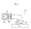
- a corona discharge treatment apparatus as shown in Fig. 3 wherein one of two electrodes is covered with an insulating material, and both the two electrodes are provided in the vicinity of the treatment face.
- Corona discharge treatment is performed so as to make a generated corona contact with the treatment face by applying a high-frequency voltage between the two electrodes. This method is preferable, since surface treatment can be applied even to a non-conductive and thick, large sized substrate.
- a corona discharge treatment apparatus 40 of Fig. 3 includes a first electrode 41 made of a stainless steel bar covered with a covering member 44 in the shape of a roller.
- the first electrode 41 is provided in the vicinity of a treatment face 10S of a substrate 10 and can move on the treatment face 10S with rotating thereon.
- the corona discharge treatment apparatus 40 further includes a second electrode 42 made of a stainless steel plane plate provided in the vicinity of first electrode 41 on the same side as the first electrode 41 with respect to the treatment face 10S.
- the corona discharge treatment apparatus 40 also includes a high-voltage generator 43 connected to both the electrodes 41 and 42, having a high-frequency generator 43A and a high-voltage transformer 43B.
- the above-mentioned covering member 44 is made of a silicone rubber, natural rubber or a ceramic material.
- the corona discharge treatment is carried out by applying a high-frequency high-voltage so as to generate a corona between both the electrodes 41 and 42 after the substrate 10 having the treatment face 10S is positioned.
- the second electrode 42 moves on the treatment face 10S with the rotation of the above-mentioned covering member 44, by maintaining a predetermined distance between the first electrode 41 and the second electrode 42. Therefore, the corona generated between the first electrode 41 and the second electrode 42 moves along the treatment face 10S, whereby the treatment face 10S is uniformly treated by corona discharge treatment.
- an surrounding gas air is used. Oxygen may also be used.
- the surface can be made hydrophilic by the above-mentioned dry treatment preferably to such a degree that the contact angle of water is in the range of about 10 to 40° .
- the reasons are as follows.
- the contact angle of water of 40° or more repels water, so that it is difficult to obtain a uniform coating.
- the contact angle of water is 10° or less, film formation by an aqueous coating agent becomes difficult.
- an antifouling coating is formed by subsequently applying an aqueous coating comprising a photocatalyst and amorphous titanium peroxide with substantially no photocatalytic capability, to the treatment face after the dry treatment.
- the antifouling coating is prepared as one single coated layer comprising a photocatalyst and amorphous titanium peroxide.
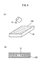
- Fig. 4(a) is a diagram for showing a step for forming a layer of antifouling coating comprising a photocatalyst and amorphous titanium peroxide.
- An aqueous coating 12 comprising a photocatalyst and amorphous titanium peroxide is applied to the treatment face after dry treatment by known methods such as spray coating, dip coating, flow-coating, roll coating and brushing.
- Fig. 4(b) is a cross section of the substrate and the antifouling coating after application of antifouling coating by the step of Fig. 4(a).
- amorphous titanium peroxide sol is preferably used in the view-point of film forming properties.
- the amorphous titanium peroxide sol can be manufactured in accordance with known methods. For instance, amorphous titanium hydroxide Ti(OH) 4 , which has been generated by adding alkali hydroxide such as sodium hydroxide to an aqueous solution of titanium salt such as titanium tetrachloride TiCl 4 , is washed, separated, and then treated with an aqueous hydrogen peroxide, whereby amorphous titanium peroxide sol is obtained.
- the amorphous titanium peroxide sol is not crystallized in the form of an anatase titanium oxide at room temperature.
- the amorphous titanium peroxide sol has extremely outstanding properties such as an excellent bonding properties, high film forming properties, and a uniform, smooth and thin film forming capability; and non-soluble characteristics and stability to the photocatalyst of the coating after drying.
- the photocatalyst contained in the above-mentioned antifouling coating it is possible to use known inorganic photocatalysts such as anatase titanium oxide, rutile titanium oxide, zinc oxide, tin oxide, bismuth dioxide, strontium titanate, barium titanate, cadmium sulfide, silicon carbide, and molybdenum disulfide, without any limitation. It is preferable to use anatase titanium oxide and rutile titanium oxide. It is particularly preferable for forming the coating to use anatase titanium oxide sol. This is because anatase titanium oxide sol liquid can form an extremely smooth surface when a contacting counterpart is hydrophilic. The anatase titanium oxide sol is prepared by heating the above-mentioned amorphous titanium peroxide sol to a temperature of 100°C or more. Moreover, the above-mentioned photocatalyst is commercially available.
- anatase titanium oxide sol is prepared by heating the above-
- the amorphous titanium peroxide functions as a binder, and will exist around the photocatalyst. Therefore, it is possible to prevent the decomposition of a plastic or a rubber by the photocatalyst. It is preferable that the ratio of the amorphous titanium peroxide to the photocatalyst is in the range of 4/1 to 1/4. When the amount of the photocatalyst is too large, it is difficult to completely prevent a plastic or a rubber from being decomposed, while when the amount of the amorphous titanium peroxide is too large, it is not possible to obtain an antifouling coating with a sufficient photocatalytic capability
- a first coating is formed by applying an aqueous coating agent comprising a amorphous titanium peroxide after the above-mentioned dry treatment, and then, a second coating is formed by applying a second coating to the first coating by applying an aqueous coating agent comprising a photocatalyst.
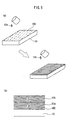
- Fig. 5(a) is a diagram for showing a step for preparing a first coating comprising amorphous titanium peroxide and a second coating comprising a photocatalyst.
- an aqueous coating agent 12a comprising amorphous titanium peroxide is applied to a treatment face 10S after dry treatment by a known method such as spray coating, dip coating, flow-coating, roll coating and brushing.
- an aqueous coating agent 12b comprising a photocatalyst is applied by a known method such as spray coating, dip coating, flow-coating, roll coating and brushing, if necessary.
- Fig. 5(b) is a cross section of the substrate and the antifouling coating after the formation of the antifouling coating by the process in Fig. 5(a).
- This embodiment for forming the first and second coatings is preferable, for example, when the adhesive property between the antifouling coating and the treating surface should be improved, when the treating surface should be prevented from deterioration by the effect of the photocatalyst, and when the hydrophilic nature of the antifouling coating should be maintained.
- the amorphous titanium peroxide contained in the first coating in this method is the above-mentioned amorphous titanium peroxide sol.
- the first coating can contain a mixture of amorphous titanium peroxide and amorphous titanium oxide. It is preferable that the ratio of amorphous titanium peroxide to amorphous titanium oxide is 1/1 or more. This is because the adhesive properties with respect to a plastic and a rubber are decreased or it is difficult to completely prevent the plastic or the rubber from decomposing, when the amount of amorphous titanium peroxide is too small.
- the thickness of the first coating is generally in the range of 0.02 to 4.0 ⁇ m, preferably in the range of 0.1 to 2.0 ⁇ m, most preferably 0.2 to 0.5 ⁇ m. The thinner the first coating, the larger the adhesive force with respect to the treatment face.
- the first coating is formed as a layer with high wear resistance and good transparency when the layer is thin.
- the second coating may comprise the above-mentioned amorphous titanium peroxide in addition to the photocatalyst. It is preferable that the ratio (based on mass) of amorphous titanium oxide to the photocatalyst is 4/1 or less. This is because the antifouling layer with a sufficient photocatalytic capability cannot be obtained when the amount of the photocatalyst is too small.
- the thickness of the second coating is generally in the range of 0.02 to 4.0 ⁇ m, preferably in the range of 0.1 to 2.0 ⁇ m, most preferably 0.3 to 1.0 ⁇ m. The thinner the second coating, the larger the adhesive force with respect to the first coating.
- the second first coating is formed as a layer with high wear resistance and good transparency when the layer is thin.
- the antifouling coating formed by the process for forming the coating of the present invention may further contain a surfactant and or a hydrophilic nature imparting agent.
- a surfactant examples include nonionic surfactant ("Cleanthrough” manufactured by Kao Corp.), anionic surfactant ("SUNNOL” manufactured by Lion Corporation) and the like.
- SUNNOL anionic surfactant
- hydrophilic nature imparting agent n-methylpyrrolidone, and silicon oxides, for instance, silicon dioxide such as colloidal silica, siloxane compound and water-glass can be used.
- a metal such as Ag, Cu and Zn for imparting antibacterial effect to the antifouling coating formed by the process for forming the coating of the present invention. It is also possible to add a metal of platinum group such as Pt, Pd, Ru, Rh and Ir. By adding such metal of platinum group, it is possible to strengthen the redox activity of the photocatalyst. Hence, it is possible to preferably promote decomposition of stain, poisonous gas and bad smell.
- a coating is prepared which is uniformly and strongly adhered to the surface of a plastic or a rubber, having an excellent photocatalytic capability, good hydrophilic nature, and weather resistance. Moreover, the plastic or rubber on the surface of the substrate does not deteriorate by the photocatalyst.
- titanium oxide sol as a photocatalyst is used together with amorphous titanium peroxide sol without photocatalytic capability, a smooth coating with excellent transparency can be formed.
- the examined cases are: the case where an acrylic undercoat layer is formed on an acrylic board, a first coating comprising amorphous titanium peroxide is formed after the undercoat layer is subjected to a corona discharge treatment by use of an apparatus as shown in Fig.
- the present invention further relates to an antifouling material having an antifouling coating, manufactured by forming the antifouling coating comprising a photocatalyst and amorphous titanium peroxide with substantially no photocatalytic capability on a treatment face of a substrate having a surface made of a plastic or a rubber.
- a wheel for an automobile such as a car and a two-wheeled vehicle having a plastic coating made of acrylic resin, fluoroplastics, or a mixture thereof on a surface of the wheel.
- Wheels of an automobile are extremely easily stained by worn tailings (rubbed pieces) of a brake pad or the like, or a combustion product such as smoke or exhaust gas. Moreover, it takes much time or burden to eliminate stain from the wheels of the automobiles.
- the wheel for an automobile, on which the antifouling coating comprising photocatalyst of the invention is provided, has excellent hydrophilic function and antifouling function when the sunlight is irradiated thereto.
- the wheel When the sunlight is not irradiated, the wheel has an excellent hydrophilic function, although there is no antifouling function. Particularly when the first coating containing amorphous titanium peroxide is formed, excellent hydrophilic function and antifouling function are maintained over a long period of time without deterioration of hydrophilic effect.
- a tire for an automobile is also preferable as the substrate.
- the number of automobiles is increased.
- effects of air pollutants such as hydrocarbons, carbon monoxide and nitrogen oxide included in exhaust gas is concerned about.
- the photocatalyst in the antifouling coating reacts with an air pollutant in the exhaust gas such as nitrogen oxide to make the air pollutant harmless. Accordingly, it is possible to decrease air pollutants in the exhaust gas.
- the luminous intensity is set 0.001 mw/cm 2 or more, preferably 0.001 mw/cm 2 or more, most preferably 0.1 mw/cm 2 .
- A-1 Plasma discharge treatment
- a substrate was made by applying an acrylic resin coating agent (clear acrylic resin coating agent, manufactured by NIPPON PAINT Co., Ltd.) to have a thickness of 30 ⁇ m to an aluminum plate with a size of 50 ⁇ 100 ⁇ 2 mm. Thereafter, baking was carried out at 160°C for 60 minutes.
- an acrylic resin coating agent (clear acrylic resin coating agent, manufactured by NIPPON PAINT Co., Ltd.) to have a thickness of 30 ⁇ m to an aluminum plate with a size of 50 ⁇ 100 ⁇ 2 mm. Thereafter, baking was carried out at 160°C for 60 minutes.
- the plasma discharge treatment was carried out by using a plasma discharge treatment apparatus as shown in Fig. 1. After fat was removed from the surface (treatment face) of the acrylic resin of the substrate with ethanol, the substrate was introduced into a glass chamber having a size of 10 ⁇ 10 ⁇ 30 mm. The chamber was evacuated, subsequently filled with O 2 gas up to 1 torr, and a plasma discharge treatment was carried out by the application of voltage with an output of 100 W for 10 minutes.
- TK-100 an aqueous solution containing 0.85 % (based on mass) of titanium peroxide, manufactured by TOA
- TOA amorphous titanium peroxide sol solution
- a red ink (PILOT Corporation), which has been diluted with water by 20 fold, was applied to the surface, UV radiation was irradiated, and the color difference was evaluated by a color difference meter (CM508d manufactured by MINOLTA Co., Ltd.). The evaluation was performed by measuring E 0 , a value before being stained, and calculating the difference ⁇ E between E 0 and E 1 , a value after being stained. The result shows that the larger the value ⁇ E, the heavier the stain.
- Example 2 The same experiment as in Example 1 was carried out except that O 2 gas as a surrounding gas for plasma discharge treatment was replaced by N 2 gas.
- Example 2 The same experiment as in Example 1 was carried out except that that O 2 gas as a surrounding gas for plasma discharge treatment was replaced by Ar gas.
- Example 1 The same experiment as in Example 1 was carried out except that the plasma discharge treatment, formation of the first layer, and formation of the second layer were not carried out.
- Example 1 Example 2
- Example 3 Comp. Ex.1 Gas Sort O 2 N 2 Ar -- Contact Angle (degree) 23 32 35 60 Film Forming Properties Good Good Good Coating cannot be applied by repelling Color Difference ⁇ E (1 hour later) 1 6 8 10 Result o ⁇ ⁇ ⁇ ⁇ ⁇
- A-2 Ultraviolet irradiation treatment
- Example 2 The same experiment as in Example 1 was carried out except that plasma discharge treatment was replaced by an ultraviolet irradiation treatment as follows:
- the ultraviolet irradiation treatment was carried out by using an ultraviolet irradiation apparatus as shown in Fig. 2. After fat was removed from the surface (treatment face) of the acrylic resin with ethanol, water was applied to the treatment face. Ultraviolet irradiation treatment was carried out in the air under normal pressure for 5 minutes by use of a 110 W low pressure UV lamp, SLTV110GS-36 manufactured by SEN Engineering with maintaining a distance between the treatment face and the low pressure UV lamp to be 1.5 cm.
- Example 4 The same experiment as in Example 4 was carried out except that water was not applied to the treatment face after removing fat on the acrylic resin surface (treatment face) with ethanol before ultraviolet irradiation treatment.
- Example 4 The same experiment as in Example 4 was carried out except that the ultraviolet irradiation treatment, formation of the first layer, and formation of the second layer were not carried out.
- Example 4 Comp. Ex. 2 Substrate Surface Acryl Acryl Acryl UV Irradiation Treatment ⁇ ⁇ ⁇ Water application for Treatment ⁇ ⁇ ⁇ Contact Angle (deg.) Before UV Irradiation 80 80 80 Treatment After UV Irradiation Treatment 28 48 - Film Forming Properties Extremely Good Good Coating cannot be applied by repelling Color Difference ⁇ E (1 hour later) 3 4 8 Result o ⁇ ⁇ ⁇ ⁇
- Acrylic resin coating agent (clear acrylic resin coating agent, manufactured by NIPPON PAINT Co., Ltd.) was applied by spray coating to the surface of an aluminum wheel, baked at 140°C for 20 minutes, and then plasma discharge treatment was applied thereto as shown in Fig. 6 (a).
- the plasma discharge treatment was carried out by introducing the above-mentioned aluminum wheel to a glass chamber, the chamber was evacuated, filled with Ar gas up to a pressure of 1 torr, and a voltage with an output of 100W was applied thereto for 10 minutes.
- the thus obtained wheel was installed to an automobile, and the stain after driving 1000 km was measured by a color difference meter (MINOLTA CM-508d).
- E 0 a value before driving, was measured in advance.
- the degree of the stain was evaluated based on the difference ⁇ E between E 0 and E 1 , a value after driving The results are shown below. The evaluation shows that the larger the value ⁇ E, the heavier the stain.
- Acrylic resin coating agent (clear acrylic resin coating agent, manufactured by NIPPON PAINT Co., Ltd.) was applied to the surface of an aluminum wheel by spray coating, baked at 140°C for 20 minutes, and then corona discharge treatment was applied thereto.
- the thus obtained wheel was installed to an automobile, and the stain after driving 5000 km was measured by a color difference meter (MINOLTA CM-508d).
- E 0 a value before driving, was measured in advance.
- the degree of the stain was evaluated based on the difference ⁇ E between E 0 and E 1 , a value after driving. The results are shown below. The evaluation shows that the larger the value ⁇ E, the heavier the stain. Dry Treatment ⁇ E Corona Discharge Treatment 0.4 Not treated 4.5
- Acrylic resin coating agent (clear acrylic resin coating agent, manufactured by NIPPON PAINT Co., Ltd.) was applied to the surface of an aluminum wheel by spray coating, baked at 140°C for 20 minutes, and then ultraviolet irradiation treatment was applied thereto.
- the ultraviolet irradiation treatment was carried out by use of an ultraviolet irradiation treatment apparatus as shown in Fig. 2.
- the ultraviolet irradiation treatment was carried out in the air under normal pressure for 5 minutes by use of a 110 W low-pressure UV lamp SLTV110GS-36 by maintaining the distance between the resin surface of the wheel and the low pressure UV lamp to be 1.5 cm.
- the thus obtained wheel was installed to an automobile, and the stain after driving 1200 km was measured by a color difference meter (MINOLTA CM-508d).
- E 0 a value before driving, was measured in advance.
- the degree of the stain was evaluated based on the difference ⁇ E between E 0 and E 1 , a value after driving. The results are shown below. The evaluation shows that the larger the value ⁇ E, the heavier the stain. Dry Treatment ⁇ E UV Irradiation Treatment 1.01 Not treated 6.12
- a corona discharge treatment as shown in Fig. 7(a) was applied to a side part of a tire of an automobile.
- an amorphous titanium peroxide sol solution (TK-100, an aqueous solution containing 0.85 % (based on mass) of titanium peroxide, manufactured by TOA) for a first coating was uniformly applied by spray coating to the treatment face after corona discharge treatment, and dried at room temperature. This operation was repeated three times. Further, an aqueous solution of anatase titanium oxide sol as the second coating was uniformly applied by spray coating, and dried at room temperature. This operation was repeated three times. Thereafter, baking was carried out in an oven at 80°C for one hour, whereby a tire was prepared which has photocatalytic activity (i.e., hydrophilic nature and organic product decomposition properties) on the side part. The thus obtained tire having the antifouling coating is shown in Fig. 7(b).
- the tire was introduced into a 1m 3 chamber, and the chamber as charged with nitrogen oxide gas having initial concentrations of 4 ppm, 8 ppm and 12 ppm.
- An ultraviolet radiation was irradiated to the above-mentioned tire by using black light (8W, 13 mW/cm 2 ) as a light source.
- black light (8W, 13 mW/cm 2 ) as a light source.
- the change of the nitrogen oxide concentration in the chamber was measured by use of U shaped gas detector tube (Kitagawa nitrogen oxide detector tube)
- the same procedure as in Example 9 was repeated except that the formation of the antifouling coating after the corona discharge treatment was changed.
- the antifouling coating was formed as follows:
- Example 10 The same procedure as in Example 10 was repeated except that corona discharge treatment was replaced by plasma discharge treatment.
- the plasma discharge treatment was carried out by using a plasma discharge treatment apparatus as shown in Fig. 1.
- the above-mentioned tire was introduced in a glass chamber, chamber was evacuated and then filled with Ar gas up to a pressure 1 torr.
- Plasma discharge treatment was performed by the application of voltage with an output of 100 W for 10 minutes.
- Example 10 The same procedure as in Example 10 was repeated except that plasma discharge treatment was replaced by ultraviolet discharge treatment.
- the ultraviolet treatment was carried out by use of a 110 W low-pressure UV lamp SUV 110GS-36 manufactured by SEN Engineering in the air under normal pressure for 5 minutes with maintaining the distance between the surface of the tire and the low pressure UV lamp to be 1.5 cm.
- Example 9 The procedure as in Example 9 was repeated except that dry treatment and film formation were not carried out.
- the results of Examples 9 to 11 and Comparative Example 3 are shown below.
- Dry treatment Initial Concentration One hour later Two hours later Example 9
- Corona discharge treatment 2nd coating TiO 2 (1) 4 ppm 2 ppm 2 ppm (2) 8 ppm 5 ppm 4 ppm (3) 12 ppm 8 ppm 7 ppm
- Corona discharge treatment 2nd coating TiO 2 /TiO 3 (1) 4 ppm 2 ppm 2 ppm (2) 8 ppm 6 ppm 4 ppm (3) 12 ppm 9 ppm 7 ppm
- Example 11 Plasma discharge treatment 2nd coating TiO 2 /TiO 3 (1) 4 ppm 3 ppm 2 ppm (2) 8 ppm 5 ppm 4 ppm (3) 12 ppm 7 ppm 6 ppm
- Example 12 UV irradiation treatment 2nd coating TiO 2 /TiO 3 (1) 4 ppm 2 ppm 1 pp
- the change of nitrogen oxide concentration was not observed in the non-treated tire. To the contrary, the nitrogen oxide concentration was decreased in the tires wherein the coatings of the photocatalyst were formed by the process for forming the coating of the present invention. It was confirmed that the tire of the present invention can decrease the concentration of nitrogen oxide in the exhaust gas of an automobile.
- an antifouling coating of the present invention a dry treatment is applied to a plastic or a rubber surface of a substrate wherein a hydrophilic group having a high reactivity is introduced, and thereafter an antifouling layer comprising a photocatalyst and amorphous titanium peroxide with substantially no catalytic capability is formed. Therefore, a uniform antifouling coating which is firmly adhered to a treatment face is formed.
- the coating which has not only with improved hydrophilic properties and weather resistance, but also excellent sealing properties, film forming properties and transparency. Furthermore, the plastic or rubber on the surface of the substrate never decomposes.
- an antifouling material having the antifouling coating of the present invention has a uniform antifouling coating comprising a photocatalyst and amorphous titanium peroxide, which coating is strongly adhered to a treatment face. Therefore, it is possible to perform purification of air, deodorization, purification of water, antibacterial treatment, and self-cleaning in a stable condition for a long period of time by use of decomposition function and hydrophilic nature imparting function of the photocatalyst.
Landscapes
- Engineering & Computer Science (AREA)
- Mechanical Engineering (AREA)
- Chemical & Material Sciences (AREA)
- Life Sciences & Earth Sciences (AREA)
- Materials Engineering (AREA)
- Wood Science & Technology (AREA)
- Organic Chemistry (AREA)
- Catalysts (AREA)
- Application Of Or Painting With Fluid Materials (AREA)
- Paints Or Removers (AREA)
- Laminated Bodies (AREA)
- Coating Of Shaped Articles Made Of Macromolecular Substances (AREA)
Abstract
Description
| Coating Agent | Dry Treatment | Wettability | Contacting Angle | Stain Degree | |
| Present Invention | Titanium Oxide / Titanium Peroxide | Corona Discharge Treatment | o ○ | o ○ | o ○ |
| Comp. Ex. | Coating Agent of general grade | Corona Discharge Treatment | ○ | ○ | ○ |
| Comp. Ex. | Coating Containing Surfactant | No Treatment | Δ | Δ | Δ |
| Example 1 | Example 2 | Example 3 | Comp. Ex.1 | |
| Gas Sort | O2 | N2 | Ar | -- |
| Contact Angle (degree) | 23 | 32 | 35 | 60 |
| Film Forming Properties | Good | Good | Good | Coating cannot be applied by repelling |
| Color Difference ΔE (1 hour later) | 1 | 6 | 8 | 10 |
| Result | o ○ | ○ | ○ | × |
| Example 4 | Example 5 | Comp. Ex. 2 | |
| Substrate Surface | Acryl | Acryl | Acryl |
| UV Irradiation Treatment | ○ | ○ | × |
| Water application for Treatment | ○ | × | × |
| Contact Angle (deg.) Before UV Irradiation | 80 | 80 | 80 |
| Treatment After UV Irradiation Treatment | 28 | 48 | - |
| Film Forming Properties | Extremely Good | Good | Coating cannot be applied by repelling |
| Color Difference ΔE (1 hour later) | 3 | 4 | 8 |
| Result | o ○ | ○ | × |
| Dry Treatment | ΔE |
| Plasma Discharge Treatment | 1.09 |
| Not treated | 8.03 |
| Dry Treatment | ΔE |
| Corona Discharge Treatment | 0.4 |
| Not treated | 4.5 |
| Dry Treatment | ΔE |
| UV Irradiation Treatment | 1.01 |
| Not treated | 6.12 |
| Dry treatment | Initial Concentration | One hour later | Two hours later | |
| Example 9 Corona discharge treatment 2nd coating TiO2 | (1) | 4 ppm | 2 ppm | 2 ppm |
| (2) | 8 ppm | 5 ppm | 4 ppm | |
| (3) | 12 ppm | 8 ppm | 7 ppm | |
| Example 10 Corona discharge treatment 2nd coating TiO2/TiO3 | (1) | 4 ppm | 2 ppm | 2 ppm |
| (2) | 8 ppm | 6 ppm | 4 ppm | |
| (3) | 12 ppm | 9 ppm | 7 ppm | |
| Example 11 Plasma discharge treatment 2nd coating TiO2/TiO3 | (1) | 4 ppm | 3 ppm | 2 ppm |
| (2) | 8 ppm | 5 ppm | 4 ppm | |
| (3) | 12 ppm | 7 ppm | 6 ppm | |
| Example 12 UV irradiation treatment 2nd coating TiO2/TiO3 | (1) | 4 ppm | 2 ppm | 1 ppm |
| (2) | 8 ppm | 4 ppm | 4 ppm | |
| (3) | 12 ppm | 8 ppm | 7 ppm | |
| Comparative Example 13 Not treated | (1) | 4 ppm | 4 ppm | 4 ppm |
| (2) | 8 ppm | 8 ppm | 8 ppm | |
| (3) | 12 | 12 | 12 ppm |
Claims (25)
- A process for forming an antifouling coating comprising a photocatalyst and amorphous titanium peroxide with substantially no photocatalytic capability provided on a treatment face of a substrate having a surface made of a plastic or a rubber, comprising:a step of performing dry treatment for introducing a hydrophilic group to the treatment face of said substrate, anda step of forming said antifouling coating by applying an aqueous coating agent comprising said photocatalyst and said amorphous titanium peroxide with substantially no photocatalytic capability to the treatment face of said substrate after said dry treatment.
- The process for forming an antifouling coating as claimed in claim 1, wherein said step of forming said antifouling coating comprises:a step of forming a first coating by applying an aqueous coating agent comprising said amorphous titanium peroxide with substantially no photocatalytic capability to said treatment face after said dry treatment; anda step of forming a second coating by applying an aqueous coating agent comprising said photocatalyst to said first coating.
- The process for forming an antifouling coating as claimed in claim 2, wherein said first coating further comprises amorphous titanium oxide with substantially no photocatalytic capability.
- The process for forming an antifouling coating as claimed in claim 2 or 3, wherein said first coating has a thickness in the range of 0.02 to 4 µm.
- The process for forming an antifouling coating as claimed in any of claims 2 to 4, wherein said second coating further comprises amorphous titanium peroxide with substantially no photocatalytic capability.
- The process for forming an antifouling coating as claimed in any of claims 2 to 5, wherein said first coating has a thickness in the range of 0.02 to 4 µm.
- The process for forming an antifouling coating as claimed in any of claims 1 to 6, wherein said photocatalyst is titanium oxide.
- The process for forming an antifouling coating as claimed in any of claims 1 to 7, wherein said antifouling coating further comprises a surfactant and/or a hydrophilic nature imparting agent.
- The process for forming an antifouling coating as claimed in any of claims 1 to 8, wherein said dry treatment is a plasma discharge treatment.
- The process for forming an antifouling coating as claimed in claim 9 wherein said plasma discharge treatment is carried out in an atmosphere of argon, oxygen or nitrogen.
- The process for forming an antifouling coating as claimed in any of claims 1 to 8, wherein said dry treatment is an ultraviolet irradiation treatment.
- The process for forming an antifouling coating as claimed in claim 11, wherein ultraviolet radiation used in said ultraviolet irradiation treatment has a wavelength in the range of 150 to 365 nm.
- The process for forming an antifouling coating as claimed in claims 11 or 12, wherein said ultraviolet irradiation treatment is carried out in an atmosphere of water vapor or ozone.
- The process for forming an antifouling coating as claimed in any of claims 11 to 13, wherein said ultraviolet treatment is carried out after water is applied to said treatment face.
- The process for forming an antifouling coating as claimed in any of claims 1 to 8, wherein said dry treatment is a corona discharge treatment.
- The process for forming an antifouling coating as claimed in claim 15, wherein said corona discharge treatment is carried out by use of a corona discharge treatment apparatus comprising two electrodes, either one of said two electrodes being covered with an insulating material, said two electrodes positioned in the vicinity of said treatment face, said corona discharge treatment being carried out so that a corona generated by applying a high-frequency voltage between said two electrodes contacts said treatment face.
- The process for forming an antifouling coating as claimed in claim 16, wherein said two electrodes are spaced from one another in a range of 1 to 5 mm.
- The process for forming an antifouling coating as claimed in claim 16 or 17, wherein a high-frequency voltage with a frequency in the range of 15 to 50 kHz, and a voltage in the range of 5 to 25 kV is applied between said two electrodes.
- An antifouling material having an antifouling coating, said antifouling material comprising a substrate having a surface made of a plastic or a rubber, and a antifouling coating comprising a photocatalyst and amorphous titanium peroxide with substantially no photocatalytic capability is provided on a treatment face of said substrate, said antifouling coating being prepared by:a step of performing dry treatment for introducing a hydrophilic group to said treatment face of said substrate, anda step of forming said antifouling coating by applying an aqueous coating agent comprising said photocatalyst and said amorphous titanium peroxide with substantially no photocatalytic capability to said treatment face of said substrate after said dry treatment.
- The antifouling material having an antifouling coating as claimed in claim 19, wherein said step of forming said antifouling coating comprises:a step of forming a first coating by applying an aqueous coating agent comprising said amorphous titanium peroxide with substantially no photocatalytic capability to said treatment face after said dry treatment; anda step of forming a second coating by applying an aqueous coating agent comprising said photocatalyst to said first coating.
- The antifouling material having an antifouling coating as claimed in claims 19 or 20, wherein said photocatalyst is titanium oxide.
- The antifouling material having an antifouling coating as claimed any of claims 19 to 21, wherein said dry treatment is any of plasma discharge treatment, ultraviolet irradiation treatment and corona discharge treatment.
- The antifouling material having an antifouling coating as claimed any of claims 19 to 22, wherein said substrate is a tire.
- The antifouling material having an antifouling coating as claimed in any of claims 19 to 22, wherein said substrate is a wheel for an automobile having a plastic covering layer on a surface of the wheel.
- The antifouling material having an antifouling coating as claimed in claim 24, wherein said plastic covering layer is made of any of acrylic resin, fluoroplastics, and a mixture thereof.
Applications Claiming Priority (7)
| Application Number | Priority Date | Filing Date | Title |
|---|---|---|---|
| JP2001128462 | 2001-03-21 | ||
| JP2001128462 | 2001-03-21 | ||
| JP2001115811 | 2001-04-13 | ||
| JP2001115811 | 2001-04-13 | ||
| JP2001118169 | 2001-04-17 | ||
| JP2001118169 | 2001-04-17 | ||
| PCT/JP2002/002648 WO2002074451A1 (en) | 2001-03-21 | 2002-03-20 | Method for forming antifouling coating and antifouling material having antifouling coating |
Publications (2)
| Publication Number | Publication Date |
|---|---|
| EP1380354A1 true EP1380354A1 (en) | 2004-01-14 |
| EP1380354A4 EP1380354A4 (en) | 2004-07-21 |
Family
ID=27346530
Family Applications (1)
| Application Number | Title | Priority Date | Filing Date |
|---|---|---|---|
| EP02713172A Withdrawn EP1380354A4 (en) | 2001-03-21 | 2002-03-20 | Method for forming antifouling coating and antifouling material having antifouling coating |
Country Status (7)
| Country | Link |
|---|---|
| US (1) | US20040131895A1 (en) |
| EP (1) | EP1380354A4 (en) |
| JP (1) | JP4121377B2 (en) |
| KR (1) | KR20030085017A (en) |
| CN (1) | CN1531465A (en) |
| TW (1) | TWI232229B (en) |
| WO (1) | WO2002074451A1 (en) |
Cited By (3)
| Publication number | Priority date | Publication date | Assignee | Title |
|---|---|---|---|---|
| EP1743763A4 (en) * | 2004-05-06 | 2012-12-26 | Sustainable Titania Technology Inc | Base protection method |
| WO2018023112A1 (en) | 2016-07-29 | 2018-02-01 | University Of Florida Research Foundation, Inc. | Contaminant-activated photocatalysis |
| EP3825014A1 (en) * | 2019-11-21 | 2021-05-26 | REHAU AG + Co | Process for coating a polymeric component, and polymeric component |
Families Citing this family (26)
| Publication number | Priority date | Publication date | Assignee | Title |
|---|---|---|---|---|
| JP4385115B2 (en) * | 2002-02-27 | 2009-12-16 | 独立行政法人産業技術総合研究所 | Sterilization system with UV and visible light active catalyst |
| JP4287695B2 (en) * | 2003-05-15 | 2009-07-01 | 株式会社ティオテクノ | Photocatalyst |
| JP4351498B2 (en) * | 2003-08-11 | 2009-10-28 | 株式会社リコー | Elastic rotating body for fixing, manufacturing method thereof, and image forming apparatus having the same |
| JP4250043B2 (en) * | 2003-09-08 | 2009-04-08 | 株式会社リコー | Elastic rotating body for fixing and image forming apparatus having the same |
| US20070044894A1 (en) * | 2005-08-31 | 2007-03-01 | The Goodyear Tire & Rubber Company | Tire preparation using plasma technology |
| JP2007177142A (en) * | 2005-12-28 | 2007-07-12 | Furukawa Co Ltd | Titania film-forming liquid and method for producing the same |
| US7707963B2 (en) * | 2006-03-31 | 2010-05-04 | 3M Innovative Properties Company | System for forming multi-layer films using corona treatments |
| US20070231495A1 (en) * | 2006-03-31 | 2007-10-04 | Ciliske Scott L | Method of forming multi-layer films using corona treatments |
| JP5256693B2 (en) * | 2007-10-31 | 2013-08-07 | 信越化学工業株式会社 | Production method of titanium oxide photocatalyst thin film |
| KR100932973B1 (en) | 2007-12-29 | 2009-12-21 | 한국타이어 주식회사 | Rubber composition for tires using photocatalyst coating |
| WO2009125846A1 (en) * | 2008-04-11 | 2009-10-15 | 中央精機株式会社 | Substrate protection method |
| WO2010089669A1 (en) * | 2009-02-06 | 2010-08-12 | Butters Brian E | Advanced oxidation enhancements and high temperature treatment of contaminated media |
| JP5255552B2 (en) * | 2009-11-20 | 2013-08-07 | 積水化学工業株式会社 | Hydrophilic coating composition, method for preparing hydrophilic coating composition, hydrophilic coating layer and building material |
| CN104775108B (en) * | 2014-01-15 | 2017-07-04 | 中国科学院理化技术研究所 | Electroless Plating of Flexible Oxide Thin Films |
| KR101891369B1 (en) | 2014-08-06 | 2018-08-27 | (주)엘지하우시스 | Photo catalyst functional films and method of manufacturing the same |
| JP6552852B2 (en) * | 2015-03-19 | 2019-07-31 | ケイミュー株式会社 | Method of manufacturing mineral board |
| JP6811731B2 (en) * | 2016-01-27 | 2021-01-13 | 日本ペイント・オートモーティブコーティングス株式会社 | Primer coating composition and coating film forming method |
| DE102016002011A1 (en) * | 2016-02-20 | 2017-08-24 | Universität Kassel | Process for improving the adhesion of silicone to a thermoplastic surface |
| BR112019006124A2 (en) * | 2016-09-29 | 2019-06-18 | Nitto Denko Corp | structure coating film, coating material set to form coating film and subcoating layer coating material |
| KR20180082706A (en) * | 2017-01-10 | 2018-07-19 | 한국교통대학교산학협력단 | Method for forming metallic nano particle on polymer surface using UV ozone |
| CN108298865B (en) * | 2018-04-09 | 2020-09-15 | 广州德雄交通科技有限公司 | Preparation method of concrete curing agent |
| JP7160506B2 (en) * | 2018-11-13 | 2022-10-25 | ダイハツ工業株式会社 | Vehicle parts contamination evaluation method |
| CN112044470B (en) * | 2020-08-28 | 2021-06-18 | 南京大学环境规划设计研究院集团股份公司 | Photocatalyst-loaded fluorocarbon fiber membrane for sewage station and preparation method thereof |
| CN112439669A (en) * | 2020-11-04 | 2021-03-05 | 漳州盈塑工业有限公司 | Process for spraying water-based paint on surface of plastic part |
| KR102895486B1 (en) * | 2022-10-27 | 2025-12-12 | 주식회사 셀코스 | Vehicle tire plating method for the same |
| CL2023001027A1 (en) * | 2023-04-10 | 2023-09-29 | Univ Santiago Chile | Ag-doped tio2 nanoparticles, composite, film, method of obtaining, and use as an exterior coating. |
Family Cites Families (23)
| Publication number | Priority date | Publication date | Assignee | Title |
|---|---|---|---|---|
| US3914521A (en) * | 1974-04-01 | 1975-10-21 | Union Carbide Corp | Heat-treated, corona-treated polymer bodies and a process for producing them |
| JPS54160474A (en) * | 1978-06-09 | 1979-12-19 | Kansai Paint Co Ltd | Modification of surface of high polymer base |
| DE3827628A1 (en) * | 1988-08-16 | 1990-03-15 | Hoechst Ag | METHOD AND DEVICE FOR THE SURFACE PRE-TREATMENT OF A MOLDED BODY MADE OF PLASTIC BY MEANS OF AN ELECTRIC CORONA DISCHARGE |
| US5527629A (en) * | 1990-12-17 | 1996-06-18 | L'air Liquide, Societe Anonyme Pour L'etude Et L'exploitation Des Procedes Georges Claude | Process of depositing a layer of silicon oxide bonded to a substrate of polymeric material using high pressure and electrical discharge |
| CH684831A5 (en) * | 1991-12-11 | 1995-01-13 | Alusuisse Lonza Services Ag | Device for producing extrusion-coated laminates. |
| US5229172A (en) * | 1993-01-19 | 1993-07-20 | Medtronic, Inc. | Modification of polymeric surface by graft polymerization |
| CA2224856C (en) * | 1995-06-22 | 2002-04-30 | Yuri Gudimenko | Surface modification of polymers and carbon-based materials |
| JP3613085B2 (en) * | 1995-12-22 | 2005-01-26 | 東陶機器株式会社 | Photocatalytic hydrophilic member |
| JPH09234375A (en) * | 1996-03-01 | 1997-09-09 | Mitsubishi Paper Mills Ltd | Photoreactive harmful material removal material |
| JP3690864B2 (en) * | 1996-03-29 | 2005-08-31 | 株式会社ティオテクノ | Production method of photocatalyst |
| JPH10237352A (en) * | 1997-02-24 | 1998-09-08 | Tao:Kk | Polyfunctional coating agent |
| JP3863620B2 (en) * | 1997-02-24 | 2006-12-27 | 株式会社ティオテクノ | Photocatalyst and method for producing the same |
| US5972176A (en) * | 1997-10-03 | 1999-10-26 | 3M Innovative Properties Company | Corona treatment of polymers |
| JP4112691B2 (en) * | 1998-04-13 | 2008-07-02 | 株式会社ティオテクノ | Surface hydrophilic substrate |
| FR2782837B1 (en) * | 1998-08-28 | 2000-09-29 | Air Liquide | METHOD AND DEVICE FOR SURFACE TREATMENT BY ATMOSPHERIC PRESSURE PLASMA |
| US6335479B1 (en) * | 1998-10-13 | 2002-01-01 | Dai Nippon Printing Co., Ltd. | Protective sheet for solar battery module, method of fabricating the same and solar battery module |
| JP2000202363A (en) * | 1999-01-19 | 2000-07-25 | Jsr Corp | Method for forming coating film and cured product obtained therefrom |
| EP1054047B1 (en) * | 1999-05-21 | 2003-03-26 | JSR Corporation | A coating composition, and a coated film and glass each having a coating layer comprised thereof |
| WO2001060920A1 (en) * | 2000-02-16 | 2001-08-23 | Jsr Corporation | Aqueous dispersion, process for production thereof and coated substances |
| EP1138732B1 (en) * | 2000-03-31 | 2005-08-31 | JSR Corporation | Coating composition and cured product |
| EP1146099B1 (en) * | 2000-04-13 | 2006-03-22 | JSR Corporation | Coating composition, method for producing the same, cured product and coating film |
| TW200422260A (en) * | 2002-11-07 | 2004-11-01 | Sustainable Titania Technology | Titania-metal complex and method for preparation thereof, and film forming method using dispersion comprising the complex |
| US7205049B2 (en) * | 2004-04-16 | 2007-04-17 | Tioxoclean Inc. | Metal peroxide films |
-
2002
- 2002-03-20 TW TW091105367A patent/TWI232229B/en not_active IP Right Cessation
- 2002-03-20 JP JP2002573155A patent/JP4121377B2/en not_active Expired - Lifetime
- 2002-03-20 KR KR10-2003-7012225A patent/KR20030085017A/en not_active Ceased
- 2002-03-20 US US10/472,248 patent/US20040131895A1/en not_active Abandoned
- 2002-03-20 WO PCT/JP2002/002648 patent/WO2002074451A1/en not_active Ceased
- 2002-03-20 EP EP02713172A patent/EP1380354A4/en not_active Withdrawn
- 2002-03-20 CN CNA02806786XA patent/CN1531465A/en active Pending
Cited By (5)
| Publication number | Priority date | Publication date | Assignee | Title |
|---|---|---|---|---|
| EP1743763A4 (en) * | 2004-05-06 | 2012-12-26 | Sustainable Titania Technology Inc | Base protection method |
| WO2018023112A1 (en) | 2016-07-29 | 2018-02-01 | University Of Florida Research Foundation, Inc. | Contaminant-activated photocatalysis |
| EP3491078A4 (en) * | 2016-07-29 | 2020-03-18 | University of Florida Research Foundation, Inc. | PHOTOCATALYSIS ACTIVATED BY CONTAMINANTS |
| US11439980B2 (en) | 2016-07-29 | 2022-09-13 | University Of Florida Research Foundation, Incorporated | Contaminant-activated photocatalysis |
| EP3825014A1 (en) * | 2019-11-21 | 2021-05-26 | REHAU AG + Co | Process for coating a polymeric component, and polymeric component |
Also Published As
| Publication number | Publication date |
|---|---|
| JPWO2002074451A1 (en) | 2004-07-08 |
| TWI232229B (en) | 2005-05-11 |
| US20040131895A1 (en) | 2004-07-08 |
| EP1380354A4 (en) | 2004-07-21 |
| CN1531465A (en) | 2004-09-22 |
| JP4121377B2 (en) | 2008-07-23 |
| WO2002074451A1 (en) | 2002-09-26 |
| KR20030085017A (en) | 2003-11-01 |
Similar Documents
| Publication | Publication Date | Title |
|---|---|---|
| US20040131895A1 (en) | Process for forming antifouling coating and antifouling material having antifouling coating | |
| EP1157741B1 (en) | Photocatalyst composite and process for producing the same | |
| CN100408184C (en) | Photocatalytic material | |
| US7327087B2 (en) | Photocatalytic fluorescent lamp provided with an anatase TiO2 coating film | |
| US20040095660A1 (en) | Antifogging element and method for forming the same | |
| EP2000208A2 (en) | Visible light response-type titanium oxide photocatalyst, method for manufacturing the visible light response-type titanium oxide photocatalyst, and use of the visible light response-type titanium oxide photocatalyst | |
| CA2604124A1 (en) | Method of making diamond-like carbon hydrophilic using barrier discharge pyrolysis | |
| JP4564018B2 (en) | Self cleaning lighting equipment | |
| US20140242289A1 (en) | Method for forming titanium oxide film on surface of molded product composed of glass | |
| JP2003306992A (en) | Antifouling panel building materials | |
| JP2000001668A (en) | Surface hydrophilic substrate | |
| JP4063577B2 (en) | Method for producing composite material having photocatalytic coating | |
| JP3694862B2 (en) | Photocatalyst-supported organic polymer material and process for producing the same | |
| CN1315955C (en) | Compositions for forming photocatalytic film and substrate provided with photocatalytic film | |
| JP4521644B2 (en) | Method for forming photocatalytic film | |
| KR100308818B1 (en) | Hydrophilic coating glass coated with porous thin layer of TiO2 | |
| JP2003306347A (en) | Antifouling glass | |
| JPH11293031A (en) | Antifouling coating and method for forming the same | |
| JP4295833B2 (en) | Method for producing glass molded body | |
| JP2003306972A (en) | Panel building material having a large number of uneven shapes and method for producing the same | |
| JP2003306563A (en) | Antifouling film and method for producing the same | |
| KR102558794B1 (en) | Hydrophilic hard coating composition containing titanium dioxide nanoparticles | |
| JP2002241522A (en) | Method and apparatus for preventing pollution by conductive polymer, purifying contaminated fluid or generating radicals, and conductive polymer and structure therefor | |
| JP2003306088A (en) | Antifouling vehicle exterior material and its manufacturing method | |
| JP2000233462A (en) | Surface porous hydrophilic substrate |
Legal Events
| Date | Code | Title | Description |
|---|---|---|---|
| PUAI | Public reference made under article 153(3) epc to a published international application that has entered the european phase |
Free format text: ORIGINAL CODE: 0009012 |
|
| 17P | Request for examination filed |
Effective date: 20030924 |
|
| AK | Designated contracting states |
Kind code of ref document: A1 Designated state(s): AT BE CH CY DE DK ES FI FR GB GR IE IT LI LU MC NL PT SE TR |
|
| AX | Request for extension of the european patent |
Extension state: AL LT LV MK RO SI |
|
| A4 | Supplementary search report drawn up and despatched |
Effective date: 20040608 |
|
| RIC1 | Information provided on ipc code assigned before grant |
Ipc: 7B 01J 37/02 B Ipc: 7B 60C 13/00 B Ipc: 7B 05D 5/00 A |
|
| STAA | Information on the status of an ep patent application or granted ep patent |
Free format text: STATUS: THE APPLICATION IS DEEMED TO BE WITHDRAWN |
|
| 18D | Application deemed to be withdrawn |
Effective date: 20040913 |