EP1380350A1 - Process and system with pig for the supply of a powder coating apparatus - Google Patents
Process and system with pig for the supply of a powder coating apparatus Download PDFInfo
- Publication number
- EP1380350A1 EP1380350A1 EP03015195A EP03015195A EP1380350A1 EP 1380350 A1 EP1380350 A1 EP 1380350A1 EP 03015195 A EP03015195 A EP 03015195A EP 03015195 A EP03015195 A EP 03015195A EP 1380350 A1 EP1380350 A1 EP 1380350A1
- Authority
- EP
- European Patent Office
- Prior art keywords
- pig
- line
- powder
- coating
- coating powder
- Prior art date
- Legal status (The legal status is an assumption and is not a legal conclusion. Google has not performed a legal analysis and makes no representation as to the accuracy of the status listed.)
- Granted
Links
- 239000000843 powder Substances 0.000 title claims abstract description 108
- 238000000034 method Methods 0.000 title claims abstract description 16
- 238000000576 coating method Methods 0.000 title claims description 91
- 239000011248 coating agent Substances 0.000 title claims description 87
- 241000282887 Suidae Species 0.000 claims description 10
- 238000005243 fluidization Methods 0.000 claims description 10
- 239000007788 liquid Substances 0.000 claims description 10
- 239000003086 colorant Substances 0.000 claims description 7
- 238000011144 upstream manufacturing Methods 0.000 claims description 3
- 230000005540 biological transmission Effects 0.000 claims 1
- 230000001276 controlling effect Effects 0.000 claims 1
- 230000001105 regulatory effect Effects 0.000 claims 1
- 239000003973 paint Substances 0.000 abstract description 9
- 238000004140 cleaning Methods 0.000 description 7
- 230000005291 magnetic effect Effects 0.000 description 3
- 239000002904 solvent Substances 0.000 description 3
- 230000002093 peripheral effect Effects 0.000 description 2
- 238000005245 sintering Methods 0.000 description 2
- 238000007664 blowing Methods 0.000 description 1
- 150000001875 compounds Chemical class 0.000 description 1
- 230000008034 disappearance Effects 0.000 description 1
- 239000012530 fluid Substances 0.000 description 1
- 239000000463 material Substances 0.000 description 1
- 239000000203 mixture Substances 0.000 description 1
- 238000012856 packing Methods 0.000 description 1
- 238000007789 sealing Methods 0.000 description 1
- 238000000926 separation method Methods 0.000 description 1
Images


Classifications
-
- B—PERFORMING OPERATIONS; TRANSPORTING
- B05—SPRAYING OR ATOMISING IN GENERAL; APPLYING FLUENT MATERIALS TO SURFACES, IN GENERAL
- B05B—SPRAYING APPARATUS; ATOMISING APPARATUS; NOZZLES
- B05B7/00—Spraying apparatus for discharge of liquids or other fluent materials from two or more sources, e.g. of liquid and air, of powder and gas
- B05B7/14—Spraying apparatus for discharge of liquids or other fluent materials from two or more sources, e.g. of liquid and air, of powder and gas designed for spraying particulate materials
- B05B7/1404—Arrangements for supplying particulate material
-
- B—PERFORMING OPERATIONS; TRANSPORTING
- B05—SPRAYING OR ATOMISING IN GENERAL; APPLYING FLUENT MATERIALS TO SURFACES, IN GENERAL
- B05B—SPRAYING APPARATUS; ATOMISING APPARATUS; NOZZLES
- B05B12/00—Arrangements for controlling delivery; Arrangements for controlling the spray area
- B05B12/14—Arrangements for controlling delivery; Arrangements for controlling the spray area for supplying a selected one of a plurality of liquids or other fluent materials or several in selected proportions to a spray apparatus, e.g. to a single spray outlet
- B05B12/1481—Arrangements for controlling delivery; Arrangements for controlling the spray area for supplying a selected one of a plurality of liquids or other fluent materials or several in selected proportions to a spray apparatus, e.g. to a single spray outlet comprising pigs, i.e. movable elements sealingly received in supply pipes, for separating different fluids, e.g. liquid coating materials from solvent or air
-
- B—PERFORMING OPERATIONS; TRANSPORTING
- B05—SPRAYING OR ATOMISING IN GENERAL; APPLYING FLUENT MATERIALS TO SURFACES, IN GENERAL
- B05B—SPRAYING APPARATUS; ATOMISING APPARATUS; NOZZLES
- B05B7/00—Spraying apparatus for discharge of liquids or other fluent materials from two or more sources, e.g. of liquid and air, of powder and gas
- B05B7/14—Spraying apparatus for discharge of liquids or other fluent materials from two or more sources, e.g. of liquid and air, of powder and gas designed for spraying particulate materials
- B05B7/1404—Arrangements for supplying particulate material
- B05B7/144—Arrangements for supplying particulate material the means for supplying particulate material comprising moving mechanical means
Definitions
- the invention relates to a method and a system for supply a powder coating device according to the preamble of independent claims. In particular, it is about the serial coating of workpieces such as vehicle bodies with powder coating.
- Powder coatings have hitherto usually been produced using an after Venturi principle working suction injector from an air fluidized container sucked in and over plastic hoses conveyed a powder-air mixture to the atomizer, whereby one promotes small powder volume in a large volume of air to overcome the pressure drop in the delivery hoses, however too high flow velocities and the resulting Inclination leads to deposits in the delivery hose.
- accretions after coating had to be done with considerable effort et al be removed by blowing the hose empty because powder residues that dissolve later disrupt the coating and lead to color errors when changing colors. "Color disappearances" so far due to incomplete hose cleaning not avoid entirely. They also go through the Hose cleaning removed powder residue for the coating lost and must be disposed of.
- the invention has for its object a method and system to supply a powder coating device, which is a precisely metered conveyance of the coating powder without the inevitable powder losses in known powder coating systems enable.
- the invention makes transport practically loss-free the amount of powder dosed exactly for a coating process allows.
- the relatively sensitive powder coating thanks to the lower transport speed high packing density transported much more gently than with the usual Venturi funding. It is advantageous also the lower air requirement for powder coating delivery.
- the pig used according to the invention not only enables lossless powder transport, but at the same time in the known from liquid paint systems a very simple cleaning of the lines by completely stripping off all adhering ones Powder residue. Through the complete hose cleaning Color spread avoided.
- the invention is particularly advantageous in other respects the color change options, for example due to short color change times and less color loss.
- An additional advantage of the invention is that in the previous usual powder coating systems not easily implemented Possibility of reflow and push-out in the known from liquid coating systems to reduce powder losses.
- the pigging back will include thereby allows the pig to work with the system described here both towards the atomizer and in the opposite direction can be pushed and promoted through the line.
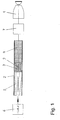
- atomizer 1 for powder coating such as on electrostatic powder rotary atomizer to one by one piggable hose formed line 2 connected through the the pig 3 the coating powder 4 towards the atomizer promotes.
- the newt 3 is indicated by one at 5 Sliding medium driven and from a loading or sending station 6 in a discharge or upstream of the atomizer 1 Target station 7 moves.
- the coating powder initiated.
- a sliding medium can serve compressed air in the example considered.
- the coating powder is said to on the side of the pig facing the destination a fluidization medium can usually be added Air to prevent powder from settling and sintering. 1 is used as the fluidization medium for the coating powder the push medium 5 of the pig 3 used that through a line passing through the pig along its direction of movement Opening such as the central bore 9 shown in the Coating powder 4 reaches the front of the pig.
- the air-permeable pig in this example is said to be attached to its Perimeter preferably completely and without gaps on the inner wall line 2 so that it moves through the line the powder is completely stripped off and no powder residue lag behind the newt. Its opening should therefore not be on its scope, but how e.g. the bore 9 radially from the peripheral parts abutting the line be distant. These peripheral parts can, as shown at the axial ends of the pig radially above the central part of the newt and protrude in a manner known per se as Sealing lips be formed.
- the pushing medium 5 of the pig 3 can be metered.
- one in the transmitter station 6 of the newt 3 included or connected to this valve assembly can be provided with which the amount, ie a certain Volume per unit of time, and / or the pressure of the sliding medium, here the compressed air, precisely controllable or regulatable are so that the pig is a correspondingly precise predetermined Powder quantity promotes.
- the air volume i.a. Proportional valves known, even those with which the Air pressure can be kept constant (e.g. similar to the color control loops described in DE 101 42 355).
- An air-permeable newt is not the only option the fluidization of the coating powder on the pig front.
- better fluidization with more uniform Air distribution can e.g. through an air permeable Reach delivery hose, which is also the frictional resistance for the newt.
- the one shown in Fig. 2 Exemplary embodiment consists of the line 12 of the coating powder from an air-permeable inner shell 20, in the pig 13 to promote the coating powder 14 of its sliding medium similar to that in Fig. 1 between its transmitting station 16 and its target station 17 is moved, and one outer shell 21 closed to the outside.
- the outer shell 21 can completely enclose the inner shell 20 and one with it annular air duct 22 for compressed air introduced from the outside form, which penetrates into the inner shell 20 and on the end face of the pig 13 fluidizes the coating powder while the pig on its back facing away from target station 17 acted upon in the drive direction.
- With the sliding air in the Line 12 can be the coating powder similar to the embodiment 1 are metered.
- the pig 13 can be impermeable to air here.
- the fluidization 2 also has the advantage of better adjustability of the Conveying and fluidizing air volumes and the conveying speed.
- a possible variation is to use the pig to convey it the coating powder with one for cleaning the pipe To drive solvents as a sliding medium, for example with cleaning fluid if for a complete separation between the solvent and the coating powder becomes.
- FIGS. 3 and 3A An embodiment is shown in FIGS. 3 and 3A, in which the conveying the coating powder 34 through the line 32 Pig 33 instead of air or other gaseous Sliding medium driven by a liquid dosing medium 31 can be that of a metering pump 35 through a line 32 concentrically surrounding ring-shaped external line. 36 pumped becomes. Suitable metering pumps are, for example, from liquid paint systems known per se.
- the dosing liquid drives the Powder pig 33 indirectly via one of her, in the outer line 36 located pushing or driving pig 37 on, the contact with the powder pig 33 non-positive due to the rod or annular magnetic elements 38 or 39 is coupled, the Magnetic field is indicated at 30.
- this sliding air for fluidizing the Serve coating powder 34.
- the coating powder could from the atomizer-side end of the line 32 be fluidized, or more generally, opposite to the conveying direction when the powder pig in both directions supports (for example in reflow mode). It is also conceivable the coating powder through one of the metering channel for the entrained pig separate external line with air-permeable Fluidize compound in the line of coating powder.
- driver pig 37 instead of the dosing liquid by dosing air or another gaseous medium as To drive the sliding medium.
- the total amount of the atomizer 41 to be fed To split coating powder 45 into several portions because the sum of the dosing errors of the subsets in some cases can be kept smaller than the error of one Total line subsidized. That from a container 40 Coming coating powder is used for this purpose in the loading or Transmitting station 46, for example, in the four shown lines leading parallel to the unloading or target station 44 42 directed and by a pig 43 through each Line conveyed to the transmitting station, where the subsets then be brought together again.
- the lines 42 and pigs 43 can be one of the exemplary embodiments 1, 2 or 3 correspond if the Do not powder on the front of the pig in any other way is fluidized.
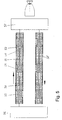
- piggable line 52 in a ring from the Transmitting station 56 to the destination station 57 and from there back to the Transmitting station.
- line 52 Through line 52, several can follow one another Newts 53, 54 are pushed, one between each Space with a predetermined volume for the coating powder to be conveyed 55 form.
- the space between neighboring ones Pigs can be connected, for example, by connecting elements 50, 51 fixed or adjustable length can be defined.
- the between the pig filled powder 55 can e.g. through an air permeable Wall of line 52 can be fluidized.
- each between the pigs Amounts of powder required for a coating process promoted the same or different color and in the Target station are taken from where the newts through the return section 52 'of line 52 is pushed back into the transmitting station in order to be able to take up redefined quantities of powder. It is also conceivable, through the annular pigged line 52, 52 'continuously between a certain coating powder to promote the sending and target stations and her the coating powder similar to the ring line of known liquid paint supply systems can only be removed if necessary.
Landscapes
- Engineering & Computer Science (AREA)
- Mechanical Engineering (AREA)
- Application Of Or Painting With Fluid Materials (AREA)
- Coating Apparatus (AREA)
- Nozzles (AREA)
- Electrostatic Spraying Apparatus (AREA)
Abstract
Description
Die Erfindung betrifft ein Verfahren und ein System zur Versorgung eines Pulverbeschichtungsgerätes gemäß dem Oberbegriff der unabhängigen Patentansprüche. Insbesondere handelt es sich um die Serienbeschichtung von Werkstücken wie beispielsweise Fahrzeugkarossen mit Pulverlack.The invention relates to a method and a system for supply a powder coating device according to the preamble of independent claims. In particular, it is about the serial coating of workpieces such as vehicle bodies with powder coating.
Pulverlacke werden bisher üblicherweise mit Hilfe eines nach dem Venturi-Prinzip arbeitenden Sauginjektors aus einem mit Luft fluidisierten Behälter angesaugt und über Kunststoffschläuche in einem Pulver-Luft-Gemisch zum Zerstäuber gefördert, wobei man geringes Pulvervolumen in einem großen Luftvolumen fördert, um den Druckabfall in den Förderschläuchen zu überwinden, was allerdings zu hohen Fließgeschwindigkeiten und der daraus resultierenden Neigung zu Anlagerungen im Förderschlauch führt. Anlagerungen mussten nach der Beschichtung mit beträchtlichem Aufwand u.a. durch Leerblasen des Schlauches entfernt werden, weil sich später wieder lösende Pulverreste die Beschichtung stören und bei einem Farbwechsel zu Farbfehlern führen. "Farbverschleppungen" lassen sich bisher wegen unvollkommener Schlauchreinigung nicht ganz vermeiden. Außerdem gehen die durch die Schlauchreinigung entfernten Pulverreste für die Beschichtung verloren und müssen entsorgt werden.Powder coatings have hitherto usually been produced using an after Venturi principle working suction injector from an air fluidized container sucked in and over plastic hoses conveyed a powder-air mixture to the atomizer, whereby one promotes small powder volume in a large volume of air to overcome the pressure drop in the delivery hoses, however too high flow velocities and the resulting Inclination leads to deposits in the delivery hose. accretions after coating had to be done with considerable effort et al be removed by blowing the hose empty because powder residues that dissolve later disrupt the coating and lead to color errors when changing colors. "Color disappearances" so far due to incomplete hose cleaning not avoid entirely. They also go through the Hose cleaning removed powder residue for the coating lost and must be disposed of.
Weitere unerwünschte Pulververluste ergeben sich durch hinsichtlich Menge und/oder Schaltzeiten ungenaue Dosierung des dem Zerstäuber zugeführten Beschichtungspulvers. Bei der Beschichtung als "Overspray" versprühtes, sich nicht auf dem Werkstück niederschlagendes Pulver kann zwar teilweise aufgefangen und zur erneuten Verwendung aufgearbeitet werden, doch ist es technologisch und ökologisch sinnvoll, die Overspraymenge so gering wie möglich zu halten. Dieses Problem wird auch durch spezielle, relativ aufwendige Dosiereinrichtungen bekannter Pulverbeschichtungsanlagen (EP 0 525 303, DE 199 37425) nicht befriedigend gelöst.Further undesirable powder losses result from Quantity and / or switching times inaccurate dosing of the atomizer supplied coating powder. When coating sprayed as "overspray" that does not deposit on the workpiece Powder can be partially collected and used reused, but it is technological and ecologically sensible, the overspray amount as low as to keep possible. This problem is also caused by special, relative complex metering devices of known powder coating systems (EP 0 525 303, DE 199 37425) unsatisfactory solved.
Die Schwierigkeiten bei der Reinigung der Pulverschläuche waren auch einer der Gründe dafür, dass es derzeit in der Praxis noch keine Pulverbeschichtungsanlagen für Fahrzeugkarossen gibt, die einen schnellen und häufigen Farbwechsel ermöglichen. Soweit in anderen Industriezweigen ein Pulverfarbwechsel vorgesehen war, musste man entweder entsprechend viele farbspezifische Lackierkabinen verwenden oder die Lackierkabine beim Farbwechsel jeweils vollständig reinigen und umrüsten (EP 0 200 681).The difficulties with cleaning the powder hoses were also one of the reasons that it is currently still in practice there are no powder coating systems for vehicle bodies that enable a quick and frequent color change. So far in other industrial sectors were intended to change powder colors, you either had to have as many color-specific paint booths use or the paint booth when changing colors completely clean and convert (EP 0 200 681).
Bei der Serienbeschichtung von Werkstücken wie Fahrzeugkarossen mit Flüssiglack häufig wechselnder Farbe werden schon seit einiger Zeit Molchsysteme u.a. zur Reduzierung von Lack- und Lösemittelverlusten eingesetzt (DE 197 09 988, DE 197 42 588, DE 100 33 986). Zur Förderung von Pulverlack konnten Molche aber bisher nicht ohne Weiteres verwendet werden, weil die übliche Fluidisierung durch die Luftströmung in Förderrichtung wegen der Sperrung der Leitung durch den Molch nicht möglich war, und wegen des hohen Reibungskoeffizienten, wegen der Neigung des Lackpulvers zu Ansinterungen unter Druck und zum Absetzen während der Förderung sowie wegen fehlender Kompressibilität.For the serial coating of workpieces such as vehicle bodies with liquid paint frequently changing color have been around for some Time pig systems etc. to reduce paint and solvent losses used (DE 197 09 988, DE 197 42 588, DE 100 33 986). But pigs were able to promote powder coating So far not easily used because the usual Fluidization due to the air flow in the direction of conveyance The line was not blocked by the newt, and because of of the high coefficient of friction due to the tendency of the paint powder for sintering under pressure and settling during funding and due to lack of compressibility.
Der Erfindung liegt die Aufgabe zugrunde, ein Verfahren und System zur Versorgung eines Pulverbeschichtungsgeräts anzugeben, die eine genau dosierte Förderung des Beschichtungspulvers ohne die bei bekannten Pulverbeschichtungsanlagen unvermeidbaren Pulverluste ermöglichen.The invention has for its object a method and system to supply a powder coating device, which is a precisely metered conveyance of the coating powder without the inevitable powder losses in known powder coating systems enable.
Diese Aufgabe wird durch die Merkmale der Patentansprüche gelöst. This object is solved by the features of the claims.
Durch die Erfindung wird ein praktisch verlustfreier Transport der jeweils exakt für einen Beschichtungsvorgang dosierten Pulvermenge ermöglicht. Zugleich wird der relativ empfindliche Pulverlack dank geringerer Transportgeschwindigkeit bei entsprechend hoher Packungsdichte wesentlich schonender transportiert als bei der bisher üblichen Venturi-Förderung. Vorteilhaft ist auch der geringere Luftbedarf zur Pulverlackförderung.The invention makes transport practically loss-free the amount of powder dosed exactly for a coating process allows. At the same time, the relatively sensitive powder coating thanks to the lower transport speed high packing density transported much more gently than with the usual Venturi funding. It is advantageous also the lower air requirement for powder coating delivery.
Eine genaue Dosierung, die u.a. die Oversprayverluste herabsetzt, wird auch durch die erfindungsgemäß möglichen kurzen Schaltzeiten beim Ein- und Ausschalten der Pulverförderung (erfindungsgemäß des Schiebemediums) erreicht.An exact dosage, which among other things reduces overspray losses, is also due to the short possible according to the invention Switching times when switching the powder feed on and off (according to the invention of the sliding medium) is reached.
Der erfindungsgemäß verwendete Molch ermöglicht aber nicht nur verlustfreien Pulvertransport, sondern zugleich in der an sich von Flüssiglacksystemen bekannten Weise eine sehr einfache Reinigung der Leitungen durch vollständiges Abstreifen aller anhaftenden Pulverreste. Durch die vollkommene Schlauchreinigung werden Farbverschleppungen vermieden.The pig used according to the invention not only enables lossless powder transport, but at the same time in the known from liquid paint systems a very simple cleaning of the lines by completely stripping off all adhering ones Powder residue. Through the complete hose cleaning Color spread avoided.
Besonders vorteilhaft ist die Erfindung im übrigen hinsichtlich der Farbwechselmöglichkeiten, etwa wegen kurzer Farbwechselzeiten und geringer Farbverluste.The invention is particularly advantageous in other respects the color change options, for example due to short color change times and less color loss.
Ein zusätzlicher Vorteil der Erfindung ist die bei den bisher üblichen Pulverlack-Beschichtungsanlagen nicht ohne Weiteres realisierbare Möglichkeit, durch Reflow und Push-Out in der an sich von Flüssiglacksystemen bekannten Weise Pulverluste zu reduzieren. Als Reflow wird das Zurückmolchen von nicht versprühten Beschichtungsmaterial aus dem zu dem Zerstäuber führenden Leitungssystem zurück in den der gemolchten Leitung vorgeschalteten Pulvervorrat bezeichnet. Das Zurückmolchen wird u.a. dadurch ermöglicht, dass der Molch bei dem hier beschriebenen System sowohl in Richtung zu dem Zerstäuber als auch in der Gegenrichtung durch die Leitung geschoben werden und fördern kann. An additional advantage of the invention is that in the previous usual powder coating systems not easily implemented Possibility of reflow and push-out in the known from liquid coating systems to reduce powder losses. As a reflow, the pigging back from non-sprayed Coating material from that leading to the atomizer Line system back into the upstream of the pigged line Called powder supply. The pigging back will include thereby allows the pig to work with the system described here both towards the atomizer and in the opposite direction can be pushed and promoted through the line.
Zweckmäßig kann hierbei zwischen die gemolchte Leitung und den Pulvervorrat eine in Richtung zu dem Pulvervorrat fördernde Pumpe geschaltet sein. Beim Push-Out wird dagegen nur die jeweils für einen Beschichtungsvorgang benötigte Pulvermenge in die gemolchte Leitung eingebracht und von dem Molch und zweckmäßigerweise eine der Leitung nachgeschaltete Pumpe in Richtung zu dem Zerstäuber gefördert.It can be useful between the pigged line and the Powder supply a pump that feeds towards the powder supply be switched. With push-out, on the other hand, only the quantity of powder required for a coating process into the pigged Line introduced and from the newt and expediently a downstream pump towards the Atomizers promoted.
An den in der Zeichnung dargestellten Ausführungsbeispielen wird die Erfindung näher erläutert. Es zeigen
- Fig. 1
- eine Leitung für Beschichtungspulver mit einem zur Fluidisierung luftdurchlässigen Molch;
- Fig. 2
- eine gemolchte Leitung für Beschichtungspulver mit einem zur Fluidisierung luftdurchlässigen Schlauch;
- Fig. 3
- eine Leitung für Beschichtungspulver mit einem Molch, der von einem mit ihm magnetisch gekuppelten Mitnehmermolch bewegt wird;
- Fig. 3A
- einen Schnitt durch Fig. 3 längs der Ebene A-A;
- Fig. 4
- eine Leitungsanordnung für Beschichtungspulver mit vier parallelen gemolchten Leitungen; und
- Fig. 5
- eine Ringleitung für Beschichtungspulver mit mehreren hintereinander durch die Leitung bewegten Molchen.
- Fig. 1
- a line for coating powder with an air-permeable pig for fluidization;
- Fig. 2
- a pigged line for coating powder with an air-permeable hose for fluidization;
- Fig. 3
- a line for coating powder with a pig which is moved by a driving pig magnetically coupled to it;
- Figure 3A
- a section through Figure 3 along the plane AA.
- Fig. 4
- a line arrangement for coating powder with four parallel pigged lines; and
- Fig. 5
- a ring line for coating powder with several pigs moved in succession through the line.
Gemäß Fig. 1 ist ein Zerstäuber 1 für Pulverlack wie z.B. ein
elektrostatischer Pulver-Rotationszerstäuber an eine durch einen
molchbaren Schlauch gebildete Leitung 2 angeschlossen, durch die
der Molch 3 das Beschichtungspulver 4 in Richtung zu dem Zerstäuber
fördert. Der Molch 3 wird von einem bei 5 angedeuteten
Schiebemedium angetrieben und aus einer Belade- oder Sendestation
6 in eine dem Zerstäuber 1 vorgeschaltete Entlade- oder
Zielstation 7 bewegt.1 is an
In der Sendestation 6 wird auf der Rückseite des Molches 3 das
Schiebemedium und auf seiner der Zielstation zugewandten Vorderseite
das Beschichtungspulver eingeleitet. Als Schiebemedium
kann bei dem betrachteten Beispiel Druckluft dienen.In the transmitting
Während seiner Förderung durch die Leitung 2 soll dem Beschichtungspulver
auf der der Zielstation zugewandten Seite des Molches
ein Fluidisierungsmedium beigemengt werden, in der Regel
Luft, um Absetzen und Ansinterungen des Pulvers zu verhindern.
Gemäß Fig. 1 wird als Fluidisierungsmedium für das Beschichtungspulver
das Schiebemedium 5 des Molches 3 verwendet, das
durch eine den Molch längs seiner Bewegungsrichtung durchsetzende
Öffnung wie z.B. die dargestellte zentrale Bohrung 9 in das
Beschichtungspulver 4 auf der Frontseite des Molches gelangt.During its promotion through
Der bei diesem Beispiel luftdurchlässige Molch soll an seinem
Umfang vorzugsweise vollständig und lückenlos an der Innenwand
der Leitung 2 anliegen, damit bei seiner Bewegung durch die Leitung
das Pulver vollständig abgestreift wird und keine Pulverreste
hinter dem Molch zurückbleiben. Seine Durchlassöffnung
soll sich deshalb nicht an seinem Umfang befinden, sondern wie
z.B. die Bohrung 9 radial von den an der Leitung anliegenden Umfangteilen
entfernt sein. Diese Umfangteile können darstellungsgemäß
an den axialen Enden des Molches radial über dem Mitteilteil
des Molches vorspringen und in an sich bekannter Weise als
Dichtlippen ausgebildet sein.The air-permeable pig in this example is said to be attached to its
Perimeter preferably completely and without gaps on the
Zum Dosieren des dem Zerstäuber 1 zugeführten Beschichtungspulvers
4 kann das Schiebemedium 5 des Molches 3 dosiert werden. Zu
diesem Zweck kann z.B. eine in der Sendestation 6 des Molches 3
enthaltene oder an diese angeschlossene Ventilanordnung (nicht
dargestellt) vorgesehen sein, mit der die Menge, also ein bestimmtes
Volumen pro Zeiteinheit, und/oder der Druck des Schiebemediums,
hier also der Druckluft, genau steuerbar oder regelbar
sind, so dass der Molch eine entsprechend genaue vorbestimmte
Pulvermenge fördert. Zur Einstellung der Luftmenge sind u.a.
Proportionalventile bekannt, auch solche, mit denen auch der
Luftdruck konstant gehalten werden kann (z.B. ähnlich wie bei
den in der DE 101 42 355 beschriebenen Farbregelkreisen).For dosing the coating powder supplied to the
Ein luftdurchlässiger Molch ist nicht die einzige Möglichkeit
der Fluidisierung des Beschichtungspulvers auf der Molchfrontseite.
Eine in manchen Fällen bessere Fluidisierung mit gleichmäßigerer
Luftverteilung lässt sich z.B. durch einen luftdurchlässigen
Förderschlauch erreichen, der zugleich den Reibungswiderstand
für den Molch herabsetzen kann. Bei dem in Fig. 2 dargestellten
Ausführungsbeispiel besteht die Leitung 12 des Beschichtungspulvers
aus einer luftdurchlässigen Innenhülle 20, in
der der Molch 13 zur Förderung des Beschichtungspulvers 14 von
seinem Schiebemedium ähnlich wie in Fig. 1 zwischen seiner Sendestation
16 und seiner Zielstation 17 bewegt wird, und einer
nach außen geschlossenen Außenhülle 21. Die Außenhülle 21 kann
die Innenhülle 20 vollständig umschließen und mit ihr einen
ringförmigen Luftkanal 22 für von außen eingeleitete Druckluft
bilden, die in die Innenhülle 20 eindringt und auf der Stirnseite
des Molches 13 das Beschichtungspulver fluidisiert, während
sie den Molch auf seiner der Zielstation 17 abgewandten Rückseite
in Antriebsrichtung beaufschlagt. Mit der Schiebeluft in der
Leitung 12 kann das Beschichtungspulver ähnlich wie bei dem Ausführungsbeispiel
nach Fig. 1 dosiert werden.An air-permeable newt is not the only option
the fluidization of the coating powder on the pig front.
In some cases, better fluidization with more uniform
Air distribution can e.g. through an air permeable
Reach delivery hose, which is also the frictional resistance
for the newt. The one shown in Fig. 2
Exemplary embodiment consists of the
Der Molch 13 kann hier luftundurchlässig sein. Die Fluidisierung
gemäß Fig. 2 hat auch den Vorteil besserer Einstellbarkeit der
Förder- und Fluidisierungs luftmengen und der Fördergeschwindigkeit. The
Eine Abwandlungsmöglichkeit besteht darin, den Molch zum Fördern des Beschichtungspulver mit einem zur Reinigung der Leitung dienenden Lösemittel als Schiebemedium anzutreiben, beispielsweise mit Reinigungsflüssigkeit, wenn für eine vollkommene Trennung zwischen dem Lösemittel und dem Beschichtungspulver gesorgt wird.A possible variation is to use the pig to convey it the coating powder with one for cleaning the pipe To drive solvents as a sliding medium, for example with cleaning fluid if for a complete separation between the solvent and the coating powder becomes.
In Fig. 3 und Fig. 3A ist ein Ausführungsbeispiel dargestellt,
bei dem der das Beschichtungspulver 34 durch die Leitung 32 fördernde
Molch 33 statt durch Luft oder ein sonstiges gasförmiges
Schiebemedium von einem flüssigen Dosiermedium 31 angetrieben
werden kann, das von einer Dosierpumpe 35 durch eine die Leitung
32 konzentrisch umgebende ringförmige Außenleitung. 36 gepumpt
wird. Geeignete Dosierpumpen sind beispielsweise aus Flüssiglacksystemen
an sich bekannt. Die Dosierflüssigkeit treibt den
Pulvermolch 33 indirekt über einen von ihr beaufschlagten, in
der Außenleitung 36 befindlichen ringförmigen Schiebe- oder Mitnehmermolch
37 an, der mit dem Pulvermolch 33 berührungslos
kraftschlüssig durch in den Molchen 33 und 37 befindliche stab-
bzw. ringförmige Magnetelemente 38 bzw. 39 gekuppelt ist, deren
Magnetfeld bei 30 angedeutet ist.An embodiment is shown in FIGS. 3 and 3A,
in which the conveying the
Zur Unterstützung des Antriebs des Pulvermolchs 33 kann dieser
zusätzlich durch Schiebeluft auf seiner Rückseite, beaufschlagt
werden. Wenn der Molch beispielsweise ähnlich wie in Fig. 1
luftdurchlässig ist, kann diese Schiebeluft zum Fluidisieren des
Beschichtungspulvers 34 dienen. Andernfalls könnte das Beschichtungspulver
von dem zerstäuberseitigen Ende der Leitung 32 her
fluidisiert werden, oder allgemeiner gesagt, entgegengesetzt zu
der Förderrichtung, wenn der Pulvermolch in beiden Richtungen
fördert (beispielsweise bei Reflow-Betrieb). Es ist auch denkbar,
das Beschichtungspulver durch eine von dem Dosierkanal für
den Mitnehmermolch getrennte Außenleitung mit luftdurchlässiger
Verbindung in die Leitung des Beschichtungspulvers zu fluidisieren. To support the drive of the
Bei dem Ausführungsbeispiel nach Fig. 3 besteht auch die Möglichkeit,
den Mitnehmermolch 37 statt mit der Dosierflüssigkeit
durch dosierende Luft oder ein sonstiges gasförmiges Medium als
Schiebemedium anzutreiben.3 there is also the possibility of
the
Zur Verbesserung der Dosiergenauigkeit kann es zweckmäßig sein,
gemäß Fig. 4 die Gesamtmenge des dem Zerstäuber 41 zuzuführenden
Beschichtungspulvers 45 in mehrere Teilmengen aufzuteilen, da
die Summe der Dosierfehler der Teilmengen in manchen Fällen
kleiner gehalten werden kann als der Fehler der in einer einzigen
Leitung geförderten Gesamtmenge. Das aus einem Behälter 40
kommende Beschichtungspulver wird zu diesem Zweck in der Beladeoder
Sendestation 46 beispielsweise in die dargestellten vier
parallel zu der Entlade- oder Zielstation 44 führenden Leitungen
42 geleitet und von je einem Molch 43 durch die jeweilige
Leitung zu der Sendestation gefördert, wo die Teilmengen dann
wieder zusammengeführt werden.To improve the dosing accuracy, it can be useful
4, the total amount of the
Mit einer Fig. 4 entsprechenden Anordnung ist es aber auch möglich,
die Leitungen 42 (oder jeweils mehrere Leitungen) jeweils
Beschichtungspulver bestimmter Farbe zuzuordnen und diese Leitungen
für unterschiedliche Farben in von Flüssiglacksystemen an
sich bekannter Weise an eine z.B. in der Zielstation 44 enthaltene
Farbwechseleinrichtung anzuschließen.With an arrangement corresponding to FIG. 4, however, it is also possible
the lines 42 (or several lines each)
Assign coating powder of a certain color and these lines
for different colors in liquid coating systems
known way to e.g. contained in the
Die Leitungen 42 und Molche 43 können einem der Ausführungsbeispiele
gemäß Fig. 1, Fig. 2 oder Fig. 3 entsprechen, wenn das
Pulver nicht auf andere Weise auf der Stirnseite des Molches
fluidisiert wird.The
Gemäß Fig. 5 führt eine molchbare Leitung 52 ringförmig von der
Sendestation 56 zu der Zielstation 57 und von dort zurück zu der
Sendestation. Durch die Leitung 52 können hintereinander mehrere
Molche 53, 54 geschoben werden, die zwischen sich jeweils einen
Raum mit vorbestimmten Volumen für das zu fördernde Beschichtungspulver
55 bilden. Der Zwischenraum zwischen benachbarten
Molchen kann beispielsweise durch Verbindungselemente 50, 51 mit
fester oder einstellbarer Länge definiert werden. Das zwischen
die Molche eingefüllte Pulver 55 kann z.B. durch eine luftdurchlässige
Wand der Leitung 52 fluidisiert werden.5 leads a
Mit einer derartigen Anordnung können zwischen den Molchen jeweils
für einen Beschichtungsvorgang benötigte Pulvermengen
gleicher oder ggf. unterschiedlicher Farbe gefördert und in der
Zielstation entnommen werden, von wo die Molche durch den Rücklaufteil
52' der Leitung 52 in die Sendestation zurückgeschoben
werden, um erneut definierte Pulvermengen aufnehmen zu können.
Es ist auch denkbar, durch die ringförmige gemolchte Leitung 52,
52' kontinuierlich ein bestimmtes Beschichtungspulver zwischen
den Sende- und Zielstationen zu fördern und ihr das Beschichtungspulver
ähnlich wie der Ringleitung bekannter Flüssiglackversorgungssysteme
nur bedarfsweise zu entnehmen.With such an arrangement can each between the pigs
Amounts of powder required for a coating process
promoted the same or different color and in the
Target station are taken from where the newts through the return section
52 'of
Claims (24)
dadurch gekennzeichnet, dass das Beschichtungspulver von einem Molch (3, 13, 33, 43, 53, 54) durch die Leitung gedrückt wird, wobei es auf der ihm zugewandten Seite des Molches fluidisiert wird.Method for supplying a powder coating device (1) with the coating powder (4), which is mixed with a fluidizing medium and conveyed through a line (2, 12, 20, 32, 42, 52) and metered to the coating device,
characterized in that the coating powder is pressed by a pig (3, 13, 33, 43, 53, 54) through the line, wherein it is fluidized on the side of the pig facing it.
durch mindestens eine durch den Molch (31) in seiner Bewegungsrichtung durchgehende Öffnung (9)
und/oder durch die für das Medium durchlässige Wand der Leitung (12) zugeführt wird.A method according to claim 1 or 2, characterized in that the fluidizing medium the coating powder
through at least one opening (9) passing through the pig (31) in its direction of movement
and / or is fed through the line (12) which is permeable to the medium.
mit einer Einrichtung zum Fluidisieren des durch die Leitung geförderten Beschichtungspulvers
und mit einer Dosiereinrichtung (6, 35) zum Dosieren des dem Beschichtungsgerät zugeführten Beschichtungspulvers,
dadurch gekennzeichnet, dass ein von einem Schiebemedium (5, 31) angetriebener Molch (3, 13, 33, 43, 53, 54) vorgesehen ist, der das Beschichtungspulver durch die Leitung fördert,
und dass das Fluidisierungsmedium auf der dem Beschichtungspulver zugewandten Seite des Molches zuführbar ist.Supply system for a powder coating device (1) which is connected to a line (2, 12, 20, 32, 42, 52) for the coating powder (4) mixed with a fluidizing medium,
with a device for fluidizing the coating powder conveyed through the line
and with a dosing device (6, 35) for dosing the coating powder supplied to the coating device,
characterized in that a pig (3, 13, 33, 43, 53, 54) driven by a pushing medium (5, 31) is provided which conveys the coating powder through the line,
and that the fluidization medium can be supplied on the side of the pig facing the coating powder.
Applications Claiming Priority (2)
| Application Number | Priority Date | Filing Date | Title |
|---|---|---|---|
| DE10231421A DE10231421A1 (en) | 2002-07-11 | 2002-07-11 | Method and system for supplying a powder coating device |
| DE10231421 | 2002-07-11 |
Publications (2)
| Publication Number | Publication Date |
|---|---|
| EP1380350A1 true EP1380350A1 (en) | 2004-01-14 |
| EP1380350B1 EP1380350B1 (en) | 2004-10-06 |
Family
ID=29723853
Family Applications (1)
| Application Number | Title | Priority Date | Filing Date |
|---|---|---|---|
| EP03015195A Expired - Lifetime EP1380350B1 (en) | 2002-07-11 | 2003-07-04 | Process and system with pig for the supply of a powder coating apparatus |
Country Status (5)
| Country | Link |
|---|---|
| US (1) | US7347649B2 (en) |
| EP (1) | EP1380350B1 (en) |
| AT (1) | ATE278474T1 (en) |
| DE (2) | DE10231421A1 (en) |
| ES (1) | ES2229187T3 (en) |
Cited By (4)
| Publication number | Priority date | Publication date | Assignee | Title |
|---|---|---|---|---|
| CN107138913A (en) * | 2017-05-11 | 2017-09-08 | 马富君 | A kind of minimizing technology of inner wall of steel pipe welding slag overlap |
| DE102018112690A1 (en) * | 2018-05-28 | 2019-11-28 | Deutsches Zentrum für Luft- und Raumfahrt e.V. | Device for deploying a mast |
| FR3098419A1 (en) * | 2019-07-12 | 2021-01-15 | Exel Industries | Fluid projection installation |
| WO2023156685A1 (en) | 2022-03-18 | 2023-08-24 | Dürr Systems Ag | Coating installation and associated operating method having a simulation of the amount of coating agent required |
Families Citing this family (13)
| Publication number | Priority date | Publication date | Assignee | Title |
|---|---|---|---|---|
| FR2870836B1 (en) * | 2004-05-27 | 2007-08-10 | F2 C2 System Sa | DEVICE ALLOWING THE MOVEMENT OF PARTS INSIDE A DRIVING |
| BRPI0613016A2 (en) * | 2005-07-15 | 2011-05-31 | Astrazeneca Ab | method and device for conveying particulate matter |
| MX2008014223A (en) * | 2006-05-12 | 2009-01-29 | Duerr Systems Gmbh | Coating plant and associated operating method. |
| US8040493B2 (en) * | 2007-10-11 | 2011-10-18 | Fresenius Medical Care Holdings, Inc. | Thermal flow meter |
| US9126754B2 (en) | 2008-12-18 | 2015-09-08 | Premium Patents Snd. Bhd | Method and system for pushing and moving solid waste |
| CN101769336B (en) * | 2009-01-05 | 2013-02-13 | 鸿富锦精密工业(深圳)有限公司 | Air guide rail |
| CN102811931A (en) * | 2010-02-07 | 2012-12-05 | 伊恩·多伊格 | Pipeline conveyor systems |
| CN102466104B (en) * | 2010-11-08 | 2015-08-26 | 通用电气公司 | Pipeline and delivery method |
| DE102014016109A1 (en) * | 2014-10-30 | 2016-05-04 | Eisenmann Se | Recovery system |
| CN105173744A (en) * | 2015-08-21 | 2015-12-23 | 天津宜诺医药工业设计有限公司 | Powder conveying pipeline and conveying method thereof |
| FR3087362B1 (en) * | 2018-10-19 | 2022-12-16 | Exel Ind | FLUID PROJECTION INSTALLATION AND METHOD FOR DISPLACEMENT OF AN ASSOCIATED FLUID |
| EP3785770A1 (en) | 2019-08-28 | 2021-03-03 | Technogym S.p.A. | Improved closed-circuit sliding-belt gymnastic machine and manufacturing method thereof |
| CN115716602A (en) * | 2022-12-15 | 2023-02-28 | 宝钢磁业(江苏)有限公司 | Automatic zinc stearate powder adding device and operation method thereof |
Citations (3)
| Publication number | Priority date | Publication date | Assignee | Title |
|---|---|---|---|---|
| DE19830029A1 (en) * | 1998-07-04 | 2000-01-05 | Audi Ag | Painting rig for vehicle bodywork |
| WO2000044504A1 (en) * | 1999-01-29 | 2000-08-03 | Kraemer Erich | Central powder supplying facility |
| EP1186349A1 (en) * | 2000-09-11 | 2002-03-13 | Abb Flexible Automation | Device for delivering one or more materials and delivery method using the same |
Family Cites Families (60)
| Publication number | Priority date | Publication date | Assignee | Title |
|---|---|---|---|---|
| US3480984A (en) * | 1968-06-17 | 1969-12-02 | Joseph V Kidd | Pig apparatus |
| US4249475A (en) * | 1978-10-10 | 1981-02-10 | Mustang Services Company | Pipeline treatment apparatus |
| US4294869A (en) * | 1979-09-26 | 1981-10-13 | Martech International, Inc. | Method for coating pipeline |
| US4376135A (en) | 1981-03-20 | 1983-03-08 | Binks Manufacturing Company | Apparatus for atomization in electrostatic coating and method |
| DE3214314A1 (en) | 1982-04-19 | 1983-10-20 | J. Wagner AG, 9450 Altstätten | ELECTROSTATIC SPRAYER |
| GB8320827D0 (en) | 1983-08-02 | 1983-09-01 | Sale Tilney Technology Ltd | Coating workpieces |
| US4589597A (en) | 1983-10-03 | 1986-05-20 | Graco Inc. | Rotary atomizer spray painting device |
| JPS60139991A (en) * | 1983-12-28 | 1985-07-24 | 東京瓦斯株式会社 | Repair system of pipe joint section of existing pipe |
| ES288858Y (en) | 1984-08-07 | 1986-10-01 | Hermann Behr & Sohn Gmbh & Co. | DEVICE FOR ELECTROSTATIC COATING OF OBJECTS |
| CH668008A5 (en) | 1985-04-30 | 1988-11-30 | H U Ramseier Fa | ELECTROSTATIC POWDER COATING SYSTEM. |
| US4684064A (en) | 1985-08-19 | 1987-08-04 | Graco Inc. | Centrifugal atomizer |
| DE3609240C2 (en) | 1986-03-19 | 1996-08-01 | Behr Industrieanlagen | Device for the electrostatic coating of objects |
| US4919333A (en) | 1986-06-26 | 1990-04-24 | The Devilbiss Company | Rotary paint atomizing device |
| JP2640812B2 (en) * | 1986-10-21 | 1997-08-13 | 協和醗酵工業株式会社 | High-concentration pneumatic transportation method and apparatus for granular material |
| ES2004334B3 (en) | 1987-03-23 | 1992-01-16 | Behr Ind Gmbh & Co | PROCEDURE FOR ELECTROSTATIC WORKPIECE COATING |
| DE3720201C1 (en) | 1987-06-16 | 1988-09-08 | Ransburg Gmbh | Spray coating device with a ring-shaped electrode arrangement for electrically conductive coating liquids |
| JPH0829825B2 (en) * | 1987-06-22 | 1996-03-27 | 協和醗酵工業株式会社 | High-concentration pneumatic transportation method and apparatus for granular material |
| JPH0195269U (en) | 1987-12-18 | 1989-06-23 | ||
| GB2215806B (en) * | 1988-02-15 | 1992-02-05 | Hakko Co | Method of applying a lining to a pipeline |
| US4927081A (en) | 1988-09-23 | 1990-05-22 | Graco Inc. | Rotary atomizer |
| JP3027837B2 (en) * | 1988-12-27 | 2000-04-04 | 協和醗酵工業株式会社 | Automatic solid sample extraction method and solid sample automatic extraction system |
| US5230842A (en) * | 1989-02-21 | 1993-07-27 | Munde Bruce A | Interior pipeline coating process |
| DE3920981A1 (en) | 1989-06-27 | 1991-01-10 | Ist Molchtechnik Gmbh | PIPING PIG |
| US4996940A (en) * | 1989-11-17 | 1991-03-05 | Cleary John J | Method and apparatus for internally coating and strengthening conduit |
| US5078321A (en) | 1990-06-22 | 1992-01-07 | Nordson Corporation | Rotary atomizer cup |
| JP2640873B2 (en) * | 1990-11-13 | 1997-08-13 | 協和醗酵工業株式会社 | Transport stopper for pneumatic transportation of solid material and method of pneumatic transportation of solid material using the same |
| DE4105116C2 (en) | 1991-02-19 | 2003-03-27 | Behr Industrieanlagen | Apparatus and method for the electrostatic coating of objects |
| DE4121455C2 (en) | 1991-06-28 | 1994-10-27 | Wagner Int | Device for feeding powder coating devices with a powder-air mixture |
| US5397063A (en) | 1992-04-01 | 1995-03-14 | Asahi Sunac Corporation | Rotary atomizer coater |
| US5633306A (en) | 1992-12-03 | 1997-05-27 | Ransburg Corporation | Nonincendive rotary atomizer |
| DE4306800C2 (en) | 1993-03-04 | 1998-07-02 | Duerr Gmbh & Co | Coating device with a rotary atomizer |
| JP3489035B2 (en) | 1993-04-07 | 2004-01-19 | ノードソン株式会社 | Powder coating equipment |
| US5300006A (en) | 1993-07-02 | 1994-04-05 | Okuma Machine Tools Inc. | Automatic tool changer |
| DE4342128A1 (en) | 1993-12-10 | 1995-06-14 | Abb Patent Gmbh | Paint sprayer |
| US5633038A (en) * | 1994-10-25 | 1997-05-27 | Atlantic Richfield Company | Method of treatment of pipelines and other steel surfaces for improved coating adhesion |
| ES2149325T3 (en) * | 1994-11-28 | 2000-11-01 | Tokyo Gas Co Ltd | PROCEDURES FOR COATING THE INTERNAL SURFACE OF A TUBE. |
| KR100204972B1 (en) | 1995-04-06 | 1999-06-15 | 스즈키 이사무 | Rotary atomizing head type painting device |
| US5683032A (en) | 1995-06-29 | 1997-11-04 | Ford Global Technologies, Inc. | Air measuring apparatus and method for paint rotary bell atomizers |
| JP3322100B2 (en) | 1995-11-09 | 2002-09-09 | 日産自動車株式会社 | Rotary atomizing electrostatic coating equipment |
| DE19610588B4 (en) | 1996-03-18 | 2010-08-05 | Dürr Systems GmbH | Coating machine with replaceable container |
| DE19611369A1 (en) | 1996-03-22 | 1997-09-25 | Duerr Gmbh & Co | Rotary atomizer for electrostatically assisted coating of objects with paints or varnishes |
| JPH09276750A (en) | 1996-04-16 | 1997-10-28 | Toyota Motor Corp | Rotary-atomization electrostatic coater |
| DE19709988C2 (en) | 1997-03-11 | 2002-01-24 | Inlac Ind Lackieranlagen Gmbh | Painting device with several circular color lines |
| DE19728155A1 (en) | 1997-07-03 | 1999-01-07 | Lactec Gmbh | Cleaning and preparation method for paint spray pipe |
| DE19742588B4 (en) | 1997-09-26 | 2009-02-19 | Dürr Systems GmbH | Method for serial coating of workpieces |
| CA2282591C (en) | 1998-01-13 | 2002-08-13 | Abb K.K. | Rotary atomizing head type coating system |
| DE19805938A1 (en) | 1998-02-13 | 1999-08-19 | Lactec Gmbh | Method and device for coating parts |
| DE19909369A1 (en) | 1999-03-03 | 2000-09-21 | Daimler Chrysler Ag | Electrostatic atomizer with housing has area of housing facing bell-shaped disc or part (air guidance ring) connected to housing with at least one earthed collection electrode |
| JP3648134B2 (en) | 1999-07-13 | 2005-05-18 | Abb株式会社 | Automatic painting equipment |
| DE19937425A1 (en) | 1999-08-07 | 2001-03-15 | Eisenmann Lacktechnik Kg | Painting device for powder coating |
| DE19959473A1 (en) | 1999-12-10 | 2001-06-13 | Frederic Dietrich | Device and method for the pneumatic conveying of powdery substances and use of the device |
| DE19961271A1 (en) | 1999-12-18 | 2001-07-05 | Duerr Systems Gmbh | Painting device |
| DE10001570A1 (en) | 2000-01-15 | 2001-07-19 | Lactec Gmbh | Electrostatic rotary atomizer |
| DE10033987A1 (en) | 2000-07-13 | 2002-01-24 | Duerr Systems Gmbh | Process for supplying a coating member for the electrostatic series coating of workpieces and supply system therefor |
| DE10033986A1 (en) | 2000-07-13 | 2002-01-24 | Duerr Systems Gmbh | Process for using a pig in a coating installation and pig therefor |
| DE10059041C2 (en) | 2000-11-28 | 2002-11-14 | Lactec Ges Fuer Moderne Lackte | Method and device for conveying electrically conductive paints between different voltage potentials |
| DE10063234C1 (en) | 2000-12-19 | 2002-07-04 | Duerr Systems Gmbh | Hose system, for coating vehicle bodywork, has an inner hose with a moving pig through it held without kinks in an outer hose by compressed air in the ring zone between them |
| DE10130173A1 (en) | 2001-06-22 | 2003-01-02 | Duerr Systems Gmbh | Powder coating plant |
| DE10142355A1 (en) | 2001-08-30 | 2003-03-20 | Duerr Systems Gmbh | Coating plant with a control loop |
| DE10301942A1 (en) * | 2003-01-20 | 2004-07-29 | Dürr Systems GmbH | Apparatus for conveying liquid paint from a cannister through a supply line to an electrostatic applicator, comprises first and second pigs, the movement of which from first station to second station delivers solvent to applicator |
-
2002
- 2002-07-11 DE DE10231421A patent/DE10231421A1/en not_active Withdrawn
-
2003
- 2003-07-04 DE DE50300100T patent/DE50300100D1/en not_active Expired - Lifetime
- 2003-07-04 ES ES03015195T patent/ES2229187T3/en not_active Expired - Lifetime
- 2003-07-04 AT AT03015195T patent/ATE278474T1/en not_active IP Right Cessation
- 2003-07-04 EP EP03015195A patent/EP1380350B1/en not_active Expired - Lifetime
- 2003-07-11 US US11/184,013 patent/US7347649B2/en not_active Expired - Fee Related
Patent Citations (3)
| Publication number | Priority date | Publication date | Assignee | Title |
|---|---|---|---|---|
| DE19830029A1 (en) * | 1998-07-04 | 2000-01-05 | Audi Ag | Painting rig for vehicle bodywork |
| WO2000044504A1 (en) * | 1999-01-29 | 2000-08-03 | Kraemer Erich | Central powder supplying facility |
| EP1186349A1 (en) * | 2000-09-11 | 2002-03-13 | Abb Flexible Automation | Device for delivering one or more materials and delivery method using the same |
Cited By (9)
| Publication number | Priority date | Publication date | Assignee | Title |
|---|---|---|---|---|
| CN107138913A (en) * | 2017-05-11 | 2017-09-08 | 马富君 | A kind of minimizing technology of inner wall of steel pipe welding slag overlap |
| DE102018112690A1 (en) * | 2018-05-28 | 2019-11-28 | Deutsches Zentrum für Luft- und Raumfahrt e.V. | Device for deploying a mast |
| US10717628B2 (en) | 2018-05-28 | 2020-07-21 | Deutsches Zentrum Fuer Luft-Und Raumfahrt E.V. | Apparatus for unfolding a mast |
| DE102018112690B4 (en) | 2018-05-28 | 2022-02-17 | Deutsches Zentrum für Luft- und Raumfahrt e.V. | Device for unfolding a rolled-up elongate hollow body |
| FR3098419A1 (en) * | 2019-07-12 | 2021-01-15 | Exel Industries | Fluid projection installation |
| WO2021009046A1 (en) * | 2019-07-12 | 2021-01-21 | Exel Industries | Apparatus for spraying a fluid |
| US11998936B2 (en) | 2019-07-12 | 2024-06-04 | Exel Industries | Apparatus for spraying a fluid |
| WO2023156685A1 (en) | 2022-03-18 | 2023-08-24 | Dürr Systems Ag | Coating installation and associated operating method having a simulation of the amount of coating agent required |
| DE102022106432A1 (en) | 2022-03-18 | 2023-09-21 | Dürr Systems Ag | Coating system and associated operating process with a simulation of the required amount of coating agent |
Also Published As
| Publication number | Publication date |
|---|---|
| DE50300100D1 (en) | 2004-11-11 |
| DE10231421A1 (en) | 2004-01-22 |
| ES2229187T3 (en) | 2005-04-16 |
| US7347649B2 (en) | 2008-03-25 |
| ATE278474T1 (en) | 2004-10-15 |
| EP1380350B1 (en) | 2004-10-06 |
| US20060000933A1 (en) | 2006-01-05 |
Similar Documents
| Publication | Publication Date | Title |
|---|---|---|
| EP1380350B1 (en) | Process and system with pig for the supply of a powder coating apparatus | |
| DE102012210439B4 (en) | Apparatus for conveying coating powder from a powder container and method for cleaning a powder conveying apparatus | |
| DE69109949T2 (en) | Improvements in or related to electrostatic insulation and pumping of electrically conductive coating materials. | |
| DE102011004352B4 (en) | Device for the pneumatic conveying of powder | |
| EP1270087B1 (en) | Powder coating installation | |
| DE69834306T2 (en) | Apparatus and method for applying a coating | |
| DE102010039473B4 (en) | Powder supply device for a powder coating system | |
| EP1314483B1 (en) | Method and system for metered delivery of coating material to a coating apparatus | |
| EP1858647A1 (en) | Device for guiding powdery fluidic media | |
| DE102007041551A1 (en) | Powder spray coating apparatus and coating powder conveying apparatus therefor | |
| DE2849269B1 (en) | Powder spraying method and pneumatic powder spraying device | |
| DE69414872T2 (en) | POWDER SPRAY COATING | |
| DE19748375A1 (en) | Method and device for powder spray coating | |
| DE69408318T2 (en) | FEEDING DEVICE AND METHOD OF A SPRAYING SYSTEM FOR A POWDERED MATERIAL | |
| DE19748376A1 (en) | Method and device for powder spray coating | |
| DE102007048520A1 (en) | Spray Coating Powder Conveyor and Powder Spray Coater | |
| DE102014223307B4 (en) | Powder container for supplying a spray coating system with coating powder | |
| DE69331148T2 (en) | POWDER APPLICATION SYSTEM FOR POWDERS HARD TO HANDLE | |
| DE19939375C2 (en) | Conveyor | |
| EP0396223A2 (en) | Method and apparatus for flushing residual paint from the internal flow passages in a paint distribution system | |
| DE102006005209A1 (en) | Vacuum lance for powder coating system has devices for feeding fluidizing air into suction head with air outlet openings on outer surface facing away from powder inlet opening | |
| DE212008000020U1 (en) | Dense-flow pump for fine-powdered material | |
| DE10003077C2 (en) | Device and method for electrostatic powder coating of workpieces with different powders | |
| DE20306234U1 (en) | Powder delivery device has rod-shaped housing, fluidizing air channel feeding fluidizing air to fluidizing unit and delivery air channel delivering delivery air to injector nozzle | |
| CH701956A1 (en) | Device for application of powder lacquer for coating e.g. three part canned body, has discharge line that sprays fluidization powder, and vacuum area directly connected with powder in container |
Legal Events
| Date | Code | Title | Description |
|---|---|---|---|
| PUAI | Public reference made under article 153(3) epc to a published international application that has entered the european phase |
Free format text: ORIGINAL CODE: 0009012 |
|
| AK | Designated contracting states |
Kind code of ref document: A1 Designated state(s): AT BE BG CH CY CZ DE DK EE ES FI FR GB GR HU IE IT LI LU MC NL PT RO SE SI SK TR |
|
| AX | Request for extension of the european patent |
Extension state: AL LT LV MK |
|
| 17P | Request for examination filed |
Effective date: 20040128 |
|
| GRAP | Despatch of communication of intention to grant a patent |
Free format text: ORIGINAL CODE: EPIDOSNIGR1 |
|
| GRAS | Grant fee paid |
Free format text: ORIGINAL CODE: EPIDOSNIGR3 |
|
| GRAA | (expected) grant |
Free format text: ORIGINAL CODE: 0009210 |
|
| AK | Designated contracting states |
Kind code of ref document: B1 Designated state(s): AT BE BG CH CY CZ DE DK EE ES FI FR GB GR HU IE IT LI LU MC NL PT RO SE SI SK TR |
|
| AKX | Designation fees paid |
Designated state(s): AT BE BG CH CY CZ DE DK EE ES FI FR GB GR HU IE IT LI LU MC NL PT RO SE SI SK TR |
|
| PG25 | Lapsed in a contracting state [announced via postgrant information from national office to epo] |
Ref country code: CZ Free format text: LAPSE BECAUSE OF FAILURE TO SUBMIT A TRANSLATION OF THE DESCRIPTION OR TO PAY THE FEE WITHIN THE PRESCRIBED TIME-LIMIT Effective date: 20041006 Ref country code: TR Free format text: LAPSE BECAUSE OF FAILURE TO SUBMIT A TRANSLATION OF THE DESCRIPTION OR TO PAY THE FEE WITHIN THE PRESCRIBED TIME-LIMIT Effective date: 20041006 Ref country code: SK Free format text: LAPSE BECAUSE OF FAILURE TO SUBMIT A TRANSLATION OF THE DESCRIPTION OR TO PAY THE FEE WITHIN THE PRESCRIBED TIME-LIMIT Effective date: 20041006 Ref country code: SI Free format text: LAPSE BECAUSE OF FAILURE TO SUBMIT A TRANSLATION OF THE DESCRIPTION OR TO PAY THE FEE WITHIN THE PRESCRIBED TIME-LIMIT Effective date: 20041006 Ref country code: RO Free format text: LAPSE BECAUSE OF FAILURE TO SUBMIT A TRANSLATION OF THE DESCRIPTION OR TO PAY THE FEE WITHIN THE PRESCRIBED TIME-LIMIT Effective date: 20041006 Ref country code: IE Free format text: LAPSE BECAUSE OF FAILURE TO SUBMIT A TRANSLATION OF THE DESCRIPTION OR TO PAY THE FEE WITHIN THE PRESCRIBED TIME-LIMIT Effective date: 20041006 Ref country code: BG Free format text: LAPSE BECAUSE OF FAILURE TO SUBMIT A TRANSLATION OF THE DESCRIPTION OR TO PAY THE FEE WITHIN THE PRESCRIBED TIME-LIMIT Effective date: 20041006 Ref country code: FI Free format text: LAPSE BECAUSE OF FAILURE TO SUBMIT A TRANSLATION OF THE DESCRIPTION OR TO PAY THE FEE WITHIN THE PRESCRIBED TIME-LIMIT Effective date: 20041006 Ref country code: EE Free format text: LAPSE BECAUSE OF FAILURE TO SUBMIT A TRANSLATION OF THE DESCRIPTION OR TO PAY THE FEE WITHIN THE PRESCRIBED TIME-LIMIT Effective date: 20041006 |
|
| REG | Reference to a national code |
Ref country code: GB Ref legal event code: FG4D Free format text: NOT ENGLISH |
|
| REG | Reference to a national code |
Ref country code: CH Ref legal event code: EP |
|
| GBT | Gb: translation of ep patent filed (gb section 77(6)(a)/1977) | ||
| REG | Reference to a national code |
Ref country code: IE Ref legal event code: FG4D Free format text: GERMAN |
|
| REF | Corresponds to: |
Ref document number: 50300100 Country of ref document: DE Date of ref document: 20041111 Kind code of ref document: P |
|
| PG25 | Lapsed in a contracting state [announced via postgrant information from national office to epo] |
Ref country code: DK Free format text: LAPSE BECAUSE OF FAILURE TO SUBMIT A TRANSLATION OF THE DESCRIPTION OR TO PAY THE FEE WITHIN THE PRESCRIBED TIME-LIMIT Effective date: 20050106 Ref country code: GR Free format text: LAPSE BECAUSE OF FAILURE TO SUBMIT A TRANSLATION OF THE DESCRIPTION OR TO PAY THE FEE WITHIN THE PRESCRIBED TIME-LIMIT Effective date: 20050106 |
|
| PG25 | Lapsed in a contracting state [announced via postgrant information from national office to epo] |
Ref country code: HU Free format text: LAPSE BECAUSE OF FAILURE TO SUBMIT A TRANSLATION OF THE DESCRIPTION OR TO PAY THE FEE WITHIN THE PRESCRIBED TIME-LIMIT Effective date: 20050107 |
|
| REG | Reference to a national code |
Ref country code: SE Ref legal event code: TRGR |
|
| REG | Reference to a national code |
Ref country code: ES Ref legal event code: FG2A Ref document number: 2229187 Country of ref document: ES Kind code of ref document: T3 |
|
| REG | Reference to a national code |
Ref country code: IE Ref legal event code: FD4D |
|
| ET | Fr: translation filed | ||
| PG25 | Lapsed in a contracting state [announced via postgrant information from national office to epo] |
Ref country code: LU Free format text: LAPSE BECAUSE OF NON-PAYMENT OF DUE FEES Effective date: 20050704 Ref country code: AT Free format text: LAPSE BECAUSE OF NON-PAYMENT OF DUE FEES Effective date: 20050704 Ref country code: CY Free format text: LAPSE BECAUSE OF FAILURE TO SUBMIT A TRANSLATION OF THE DESCRIPTION OR TO PAY THE FEE WITHIN THE PRESCRIBED TIME-LIMIT Effective date: 20050704 |
|
| PG25 | Lapsed in a contracting state [announced via postgrant information from national office to epo] |
Ref country code: MC Free format text: LAPSE BECAUSE OF NON-PAYMENT OF DUE FEES Effective date: 20050731 |
|
| PLBE | No opposition filed within time limit |
Free format text: ORIGINAL CODE: 0009261 |
|
| STAA | Information on the status of an ep patent application or granted ep patent |
Free format text: STATUS: NO OPPOSITION FILED WITHIN TIME LIMIT |
|
| 26N | No opposition filed |
Effective date: 20050707 |
|
| PG25 | Lapsed in a contracting state [announced via postgrant information from national office to epo] |
Ref country code: PT Free format text: LAPSE BECAUSE OF NON-PAYMENT OF DUE FEES Effective date: 20050306 |
|
| REG | Reference to a national code |
Ref country code: CH Ref legal event code: PL |
|
| PG25 | Lapsed in a contracting state [announced via postgrant information from national office to epo] |
Ref country code: LI Free format text: LAPSE BECAUSE OF NON-PAYMENT OF DUE FEES Effective date: 20070731 Ref country code: CH Free format text: LAPSE BECAUSE OF NON-PAYMENT OF DUE FEES Effective date: 20070731 |
|
| REG | Reference to a national code |
Ref country code: FR Ref legal event code: PLFP Year of fee payment: 13 |
|
| PGFP | Annual fee paid to national office [announced via postgrant information from national office to epo] |
Ref country code: FR Payment date: 20150626 Year of fee payment: 13 |
|
| PGFP | Annual fee paid to national office [announced via postgrant information from national office to epo] |
Ref country code: NL Payment date: 20150721 Year of fee payment: 13 |
|
| PGFP | Annual fee paid to national office [announced via postgrant information from national office to epo] |
Ref country code: ES Payment date: 20150728 Year of fee payment: 13 Ref country code: GB Payment date: 20150721 Year of fee payment: 13 Ref country code: DE Payment date: 20150721 Year of fee payment: 13 |
|
| PGFP | Annual fee paid to national office [announced via postgrant information from national office to epo] |
Ref country code: BE Payment date: 20150721 Year of fee payment: 13 Ref country code: SE Payment date: 20150721 Year of fee payment: 13 |
|
| PGFP | Annual fee paid to national office [announced via postgrant information from national office to epo] |
Ref country code: IT Payment date: 20150727 Year of fee payment: 13 |
|
| REG | Reference to a national code |
Ref country code: DE Ref legal event code: R082 Ref document number: 50300100 Country of ref document: DE Representative=s name: V. BEZOLD & PARTNER PATENTANWAELTE - PARTG MBB, DE Ref country code: DE Ref legal event code: R081 Ref document number: 50300100 Country of ref document: DE Owner name: DUERR SYSTEMS AG, DE Free format text: FORMER OWNER: DUERR SYSTEMS GMBH, 74321 BIETIGHEIM-BISSINGEN, DE |
|
| PG25 | Lapsed in a contracting state [announced via postgrant information from national office to epo] |
Ref country code: BE Free format text: LAPSE BECAUSE OF NON-PAYMENT OF DUE FEES Effective date: 20160731 |
|
| REG | Reference to a national code |
Ref country code: DE Ref legal event code: R119 Ref document number: 50300100 Country of ref document: DE |
|
| REG | Reference to a national code |
Ref country code: NL Ref legal event code: MM Effective date: 20160801 |
|
| REG | Reference to a national code |
Ref country code: SE Ref legal event code: EUG |
|
| REG | Reference to a national code |
Ref country code: DE Ref legal event code: R082 Ref document number: 50300100 Country of ref document: DE Representative=s name: V. BEZOLD & PARTNER PATENTANWAELTE - PARTG MBB, DE Ref country code: DE Ref legal event code: R081 Ref document number: 50300100 Country of ref document: DE Owner name: DUERR SYSTEMS AG, DE Free format text: FORMER OWNER: DUERR SYSTEMS AG, 74321 BIETIGHEIM-BISSINGEN, DE |
|
| GBPC | Gb: european patent ceased through non-payment of renewal fee |
Effective date: 20160704 |
|
| PG25 | Lapsed in a contracting state [announced via postgrant information from national office to epo] |
Ref country code: DE Free format text: LAPSE BECAUSE OF NON-PAYMENT OF DUE FEES Effective date: 20170201 Ref country code: SE Free format text: LAPSE BECAUSE OF NON-PAYMENT OF DUE FEES Effective date: 20160705 Ref country code: FR Free format text: LAPSE BECAUSE OF NON-PAYMENT OF DUE FEES Effective date: 20160801 Ref country code: NL Free format text: LAPSE BECAUSE OF NON-PAYMENT OF DUE FEES Effective date: 20160801 |
|
| REG | Reference to a national code |
Ref country code: FR Ref legal event code: ST Effective date: 20170331 |
|
| PG25 | Lapsed in a contracting state [announced via postgrant information from national office to epo] |
Ref country code: GB Free format text: LAPSE BECAUSE OF NON-PAYMENT OF DUE FEES Effective date: 20160704 |
|
| PG25 | Lapsed in a contracting state [announced via postgrant information from national office to epo] |
Ref country code: IT Free format text: LAPSE BECAUSE OF NON-PAYMENT OF DUE FEES Effective date: 20160704 |
|
| PG25 | Lapsed in a contracting state [announced via postgrant information from national office to epo] |
Ref country code: ES Free format text: LAPSE BECAUSE OF NON-PAYMENT OF DUE FEES Effective date: 20160705 |
|
| REG | Reference to a national code |
Ref country code: ES Ref legal event code: FD2A Effective date: 20181130 |
|
| P01 | Opt-out of the competence of the unified patent court (upc) registered |
Effective date: 20230512 |