EP1380104B1 - Tiefpassfilter mit ausschliesslich passiven elementen zur entkopplung der xdsl-übertrangungskanäle - Google Patents
Tiefpassfilter mit ausschliesslich passiven elementen zur entkopplung der xdsl-übertrangungskanäle Download PDFInfo
- Publication number
- EP1380104B1 EP1380104B1 EP02722394A EP02722394A EP1380104B1 EP 1380104 B1 EP1380104 B1 EP 1380104B1 EP 02722394 A EP02722394 A EP 02722394A EP 02722394 A EP02722394 A EP 02722394A EP 1380104 B1 EP1380104 B1 EP 1380104B1
- Authority
- EP
- European Patent Office
- Prior art keywords
- filter
- cell
- pots
- elliptic
- filter according
- Prior art date
- Legal status (The legal status is an assumption and is not a legal conclusion. Google has not performed a legal analysis and makes no representation as to the accuracy of the status listed.)
- Expired - Lifetime
Links
- 230000009977 dual effect Effects 0.000 claims abstract description 19
- 230000005540 biological transmission Effects 0.000 claims description 33
- 101150012579 ADSL gene Proteins 0.000 abstract description 6
- 102100020775 Adenylosuccinate lyase Human genes 0.000 abstract description 6
- 108700040193 Adenylosuccinate lyases Proteins 0.000 abstract description 6
- 238000001914 filtration Methods 0.000 abstract description 4
- 239000003990 capacitor Substances 0.000 description 11
- RYGMFSIKBFXOCR-UHFFFAOYSA-N Copper Chemical compound [Cu] RYGMFSIKBFXOCR-UHFFFAOYSA-N 0.000 description 5
- 229910052802 copper Inorganic materials 0.000 description 5
- 239000010949 copper Substances 0.000 description 5
- 238000009434 installation Methods 0.000 description 4
- 238000000034 method Methods 0.000 description 4
- 238000004804 winding Methods 0.000 description 3
- 230000008901 benefit Effects 0.000 description 2
- 230000008859 change Effects 0.000 description 2
- 238000003780 insertion Methods 0.000 description 2
- 230000037431 insertion Effects 0.000 description 2
- 240000008042 Zea mays Species 0.000 description 1
- 238000013461 design Methods 0.000 description 1
- 238000011161 development Methods 0.000 description 1
- 238000005516 engineering process Methods 0.000 description 1
- 230000006872 improvement Effects 0.000 description 1
- 230000006698 induction Effects 0.000 description 1
- 238000009413 insulation Methods 0.000 description 1
- 230000010354 integration Effects 0.000 description 1
- 108010072199 interleukin binding factor Proteins 0.000 description 1
- 238000005457 optimization Methods 0.000 description 1
- 230000008569 process Effects 0.000 description 1
- 238000000926 separation method Methods 0.000 description 1
- 230000011664 signaling Effects 0.000 description 1
- 230000007704 transition Effects 0.000 description 1
- 238000011144 upstream manufacturing Methods 0.000 description 1
Images


Classifications
-
- H—ELECTRICITY
- H03—ELECTRONIC CIRCUITRY
- H03H—IMPEDANCE NETWORKS, e.g. RESONANT CIRCUITS; RESONATORS
- H03H7/00—Multiple-port networks comprising only passive electrical elements as network components
- H03H7/42—Networks for transforming balanced signals into unbalanced signals and vice versa, e.g. baluns
- H03H7/425—Balance-balance networks
- H03H7/427—Common-mode filters
-
- H—ELECTRICITY
- H03—ELECTRONIC CIRCUITRY
- H03H—IMPEDANCE NETWORKS, e.g. RESONANT CIRCUITS; RESONATORS
- H03H7/00—Multiple-port networks comprising only passive electrical elements as network components
- H03H7/01—Frequency selective two-port networks
- H03H7/06—Frequency selective two-port networks including resistors
-
- H—ELECTRICITY
- H03—ELECTRONIC CIRCUITRY
- H03H—IMPEDANCE NETWORKS, e.g. RESONANT CIRCUITS; RESONATORS
- H03H7/00—Multiple-port networks comprising only passive electrical elements as network components
- H03H7/01—Frequency selective two-port networks
- H03H7/09—Filters comprising mutual inductance
Definitions
- the present invention relates to the so-called xDSL technique, typically ADSL Asynchronous Digital Subscriber Line - Asynchronous Digital Subscriber Line.
- xDSL so-called xDSL technique
- a pair of copper wires in particular twisted wires, to transmit at the same time, in baseband, unmodulated or digital analog signals modulated in baseband, and in high band. other modulated signals.
- Analog baseband signals are typically from 0 to 4000 Hz, up to 16 KHz with signaling. They are carried in analog networks called POTS (Plain Old Transmission System).
- Digital baseband signals are carried in so-called ISDN networks (or ISDN - Integrated Services Digital Network). They are modulated in baseband in frequencies from 0 to 94 KHz.
- the high band spreads from the top of the baseband to about 1 MHz.
- the high band ranges from 32 KHz to 1.1 MHz if the pair of copper wires is used as baseband for analogue transmission, and from 138 KHz to 1.1 MHz if it is used for digital transmission.
- the high band is used for digital transmission. It is normally intended for permanent transmission, in packet mode mainly, while the baseband is intended in practice for transmission in circuit mode. To simplify the explanation, it can be assumed that typically the baseband is used for the transmission of words and that typically the high band is used for data transmission, including the consultation of Internet sites. However, the bass band also serves, especially with modems (and in particular with digital modems), to transmit data, while the high band can be used to provide phonic communications. We are talking about telephone calls on the Internet.
- the baseband is only capable of a low bit rate (currently 56 Kbps for analog modems and 64 Kbits / s for digital modems) compared to a broadband (typically 10 Mbits / s) for the high band.
- ADSL a line called ADSL therefore requires, see figure 1 , from separating the baseband, low frequency - BF, from the high band, called high frequency - HF.
- An ADSL installation then has for this purpose, two pairs of filters connected in parallel on the two strands of the pair L of copper son, telephony operator side and subscriber side.
- a first filter of a pair is a BF filter the second is an HF filter.
- the first filter is connected upstream to a conventional telephony multiplexer-splitter, the second is connected to a high-speed digital transmission multiplexer-splitter.
- Subscriber side the first filter is connected to the phone, the second is connected to an ADSL modem.
- Each filter is used to isolate the installation that connects signals for the other installation.
- the subscriber-side BF filter serves to prevent a listener from hearing a permanent hiss.
- Zc is called such a characteristic impedance.
- Zc is a value imposed by a norm.
- the problem is somewhat complicated by the fact that there are five standards: the harmonized European standard, the English standard, the German standard, and two American standards known as 600 ohms and 900 ohms respectively. The differences between these standards depend on the diameter of the copper wires used, the insulation and the pitch of the twists. The common point of these standards is that only the purely resistive component of the characteristic impedance was taken into account. In addition, the impedances concerned have substantially comparable values.
- the figure 1 shows the necessary structure with either side of the L line, two low pass filters, BF to be connected to the low frequency channels, and two high pass parallel filters, HF, to be connected to the xDSL modems.
- Two other additional constraints imposed by the standards are then critical. These two constraints are the Insertion Loss - ILF insertion loss factor and the Return Loss - RLF reflection loss factor.
- the ILF loss factor measures the loss of transmission caused in the circuit by the establishment of a filter between a situation where the filter is not present and a situation where it is set up.
- RFL factor 10log 10 (Zin-Zc) / (Zin + Zc) requires a template that approximate the attenuation for the reflection 8F filter should be greater than about 18 dB in the useful baseband (300 - 3400 Hz in POTS network, and 300 - 94000 Hz in ISDN network).
- filters with active elements in particular diodes, in particular Zener diodes to separate the BF channel from the HF channel.
- active elements in particular diodes, in particular Zener diodes to separate the BF channel from the HF channel.
- the HF filter will naturally be directly incorporated into an xDSL modem, to be connected in parallel to an existing pair of copper wires (and thus will provide the HF separation filter)
- the embodiment described in the document cited above is from this point of view too expensive.
- the present applicant has also made a low pass filter for this purpose.
- a first low-pass filter with dissipative elements which, in theory, runs up against the requirements related to ILF factor.
- Such a first filter then has to solve this problem a negative resistive impedance.
- Such negative resistance can only be achieved on the basis of an active filter, with operational amplifiers.
- Such an embodiment therefore requires a power supply, which is not feasible because prohibited for conventional telephone systems (those for which the installed phone does not have its own power supply).
- Figures 2a and 2b the LC dipoles in parallel, possibly in parallel with a resistor.
- Figure 2c quadrupoles to insert in a line with filter cells whose poles are at infinity.
- the low pass cell is in Pi with inductances in a transmission branch and capacitors in parallel between the branches.
- this type of filter is not suitable.
- the filter of the figure 2d is made symmetrical, the components in a branch of transmission, the upper branch here, being of the same value and identical to the components in the other branch, the lower branch.
- the right pace of the figure 2e shows a cell, preferred, symmetrical and dual of a theoretical elliptical cell.
- This dual elliptical and symmetrical structure forms a basic structure of the filters of the invention.
- These filters Figures 2d and 2e have the advantage of having a steep transition band, in which the attenuation increases sharply between a last zero and a first pole of the filter. Such an elliptical filter therefore makes it possible to have a strong rejection of the xDSL signals.
- the subject of the invention is therefore a passive pass filter with only passive components, to be used for connecting a low frequency channel to a two-wire line, this two-wire line delivering signals in this low frequency channel and signals in a high frequency channel. , characterized in that it comprises at least one elliptical or dual elliptical type cell and a dissipative dipole interposed as a corrective structure in the transmission.
- the cells used will preferably be symmetrical cells, with LC resonant elements or inductors in both branches, because of the capacitor economy.
- inductances in principle of equal values in each branch.
- cells with elliptical dual structure will be selected. They are shown on the figure 2f .
- the elliptic dual character is in fact carried by the values of the various inductance and capacitor components.
- the invention schematically represented by the Figures 2d and 2e in one or the other of the transmission branches of these cells, or even in both, dissipative dipoles can be added. It will be shown later that the problem raised is solved.
- the solution of the figure 2e can have the disadvantage of having to perform a lot of inductances, two per cell branch.
- the four inductances of a cell (those which are connected to terminals of the same capacitor of the cell) are wound on one and the same core. We win even more in cost.
- the subject of the invention is a passive pass filter with only passive components, to be used in connection with a low frequency channel to a two-wire line, this two-wire line delivering signals in this low frequency channel and signals in a high frequency channel, characterized in that it comprises at least one elliptical and symmetrical dual type cell with four coils connected to the terminals of the same capacitor, the four coils being wound on the same core.
- the invention also relates to a low-pass filter with a structure and precisely determined component values. This solution is unique.
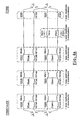
- FIGS. 3a to 3e show preferred embodiments of the low pass filter of the invention.
- the general quadrupole shown has a so-called POTS side, to be connected to a subscriber terminal, or to the operator's splitter multiplexer, and a LINE side to be connected on the line L side ( figure 1 ).
- three dual elliptical and symmetrical filtering cells (in accordance with the figure 2e right) are each cascaded.
- a dissipative element, also realized in a symmetrical form is inserted in various places of this cascade.
- the filter furthermore comprises two symmetrical inductances of connection on the LINE side, after the third cell.
- the dissipative element preferably comprises two sub-elements connected symmetrically in series in a branch.
- Each sub-element comprises a dipole RL with a resistor R5 in parallel with an inductance L5, and the same elements elided for the other branch.
- the figure 3e shows a variant of these Figures 3a to 3d in which the dissipative element is divided into two pairs of sub-elements, here a pair being placed as on the figure 3a , the other pair being placed as on the figure 3d .
- the dissipative element is divided into two pairs of sub-elements, here a pair being placed as on the figure 3a , the other pair being placed as on the figure 3d .
- Each cell comprises in a transmission branch a pair of inductors in series and mutually coupled, for example L1a pots and L1b pots, and in another branch another pair of inductors in series and also mutually coupled, for example L1a ' pots and L1b ' pots .
- a capacitor CT1 pots is connected between the intermediate nodes of the inductances in series.
- the pots index means that the filter is intended to be used to connect a two-wire line that can be used in analog. It will be seen later that a solution of the same type can be envisaged for a digital baseband line, of the ISDN type, for which the constraints are different. For this solution of the same type, the indices will be isdn.
- the Figures 4a and 4b show in particular a variant of this type, in which the filter comprises two filtered channels.
- a first channel thus concerns a use on ISDN type transmission, and the filter components are indexed isdn.
- Another way concerns a use for analog transmission, it is indexed pots.
- the filter represented is the preferred one of the figure 3d because it also gives the best results.
- a subscriber line that terminates at a customer's home is of one type or another, POTS or ISDN, not both. Indeed, the characteristics of the line change from one case to another, especially because the two-wire ISDN line is supposed to pass signals up to 94 KHz. The operator thus equips the user with one line or another as needed (and cost).
- the block proposed by the invention comprises, at the input and at the output of the two channels and also in the middle of the channels, switches enabling to put into service exclusively one or the other of these channels.
- the costs of two filters which in theory should double the cost of the block
- the figure 4a is a figure of principle, in which the two filtered channels are separated by means of four switches.
- the reels in the air of its branches transmission can, by mutual induction, unbalance the filter formed by the connected coils.
- Two switches of these four switches are used to connect the two transmission branches of one cell of a filtered channel (or the other filtered channel) to two link nodes.
- the other two switches of these four switches are used to connect the two connection nodes to the two transmission branches of the cascaded cell of the same filtered channel (or the other filtered channel respectively).
- An additional switch per cell makes it possible to connect a common midpoint to a first pair of two series inductors to a first terminal of a capacitor or to a first terminal of another capacitor, to serve for one filtered channel or the other respectively.
- the second terminals of the two capacitors are connected together and at a midpoint common to a second pair of two inductors in series.
- two symmetrical correctors and two link inductors are thus obtained a 23-switch assembly at each two positions only. These switches can be mechanical.
- the dissipative element is preferably formed by a pair of resistors and inductors.
- the inductors are preferably wound on the same core, so that the entire structure has only five cores, counting the core of the link inductances.
- L1a isdn , L1a ' isdn 52.9 ⁇ H L1b isdn , L1b ' isdn 1-6 ⁇ H L1a pots , L1a ' pots 250.0 ⁇ H L1b pots , L1b ' pots 10.0 ⁇ H CT1 isdn 13.6nF CT1 pots 6.8nF L2a isdn , L2a ' isdn 122.5 ⁇ H L2b isdn ; L2b ' isdn 3.6 ⁇ H L2a pots , L2a ' pots 211.6 ⁇ H L2b pots , L2b ' pots 6.4 ⁇ H CT2 isdn 13.6nF CT2 pots 6.8nF L3a isdn , L3a isdn 122.5 ⁇ H L3b isdn , L3b ' isdn 1.6 ⁇ H L3a pots , L3a ' pots 230.4 ⁇
Landscapes
- Filters And Equalizers (AREA)
- Coils Or Transformers For Communication (AREA)
- Telephonic Communication Services (AREA)
- Networks Using Active Elements (AREA)
- Compression, Expansion, Code Conversion, And Decoders (AREA)
Claims (13)
- Tiefpassfilter mit lediglich passiven Bauelementen, für den Anschluss eines Niederfrequenzkanals an eine Zweidrahtleitung, wobei diese Zweidrahtleitung Signale in diesen Niederfrequenzkanal und Signale in einen Hochfrequenzkanal sendet, dadurch gekennzeichnet, dass es zumindest eine elliptische Zelle (Abb. 2d) oder eine zweistufig elliptische Zelle (Abb. 2e) und einen dissipativen Dipol enthält, mit einer Induktanz (L5pots ; L5'pots) parallel zu einem Widerstand (R5pots ; R5'pots), die zwischen der Übertragungs-Zweidrahtleitung und der elliptischen oder zweistufig elliptischen Zelle geschaltet, oder zwischen einem Abonnenten-Endgerät, das mit dem Filter verbunden ist, und der elliptischen oder zweistufig elliptischen Zelle geschaltet ist.
- Filter nach Anspruch 1, dadurch gekennzeichnet, dass es zumindest drei elliptische Vierpolzellen enthält, die in zwei Übertragungskanälen zwischengeschaltet sind, wobei der dissipative Dipol zumindest in einem Kanal zwischen einer ersten und einer zweiten Zelle geschaltet ist.
- Filter nach Anspruch 2, dadurch gekennzeichnet, dass eine Zelle zwei Übertragungskanäle enthält, wobei zumindest einer dieser Kanäle eine in Reihe geschaltete Induktanz (L1apots ; L1bpots ; L1a'pots ; L1b'pots) und einen parallel geschalteten Kondensator (CT1pots) zwischen den beiden Kanälen enthält.
- Filter nach einem der Ansprüche 2 bis 3, dadurch gekennzeichnet, dass eine Zelle zwei Übertragungskanäle enthält, von denen zumindest einer eine Induktanz enthält, wobei diese Induktanz in Reihe mit einer Induktanz einer angrenzenden Zelle geschaltet ist, und ein Kondensator parallel zwischen einem Zwischenpunkt zwischen den beiden Induktanzen und dem anderen Kanal geschaltet ist.
- Filter nach Anspruch 4, dadurch gekennzeichnet, dass die beiden in Reihe geschalteten Induktanzen auf einen selben Kern gewickelt sind.
- Filter nach einem der Ansprüche 1 bis 5, dadurch gekennzeichnet, dass es symmetrisch ist.
- Filter nach Anspruch 5 und Anspruch 6, dadurch gekennzeichnet, dass zwei in einem Übertragungskanal in Reihe geschaltete Induktanzen auf einen selben Kern gewickelt sind, wie zwei in Reihe geschaltete Induktanzen des anderen Übertragungskanals.
- Filter nach einem der Ansprüche 1 bis 7, dadurch gekennzeichnet, dass der dissipative Dipol eine Induktanz enthält, die parallel zu einem Widerstand und parallel zu einem Kondensator geschaltet ist.
- Tiefpassfilter mit lediglich passiven Bauelementen, für den Anschluss eines Niederfrequenzkanals an eine Zweidrahtleitung, wobei diese Zweidrahtleitung Signale in diesen Niederfrequenzkanal und Signale in einen Hochfrequenzkanal sendet, wobei das besagte Filter einen dissipativen Dipol enthält, der in einem Übertragungskanal zwischengeschaltet ist, und zumindest eine zweistufig elliptische und symmetrische Zelle (Abb. 2e) mit vier Spulen, die an die Klemmen eines selben Kondensators angeschlossen sind, wobei die vier Spulen auf einen selben Kern gewickelt sind, dadurch gekennzeichnet, dass der dissipative Dipol eine Induktanz (L5pots ; L5'pots) parallel zu einem Widerstand (R5pots ; R5'pots) enthält.
- Filter nach Anspruch 9, dadurch gekennzeichnet, dass der dissipative Dipol eine Induktanz parallel zu einem Widerstand und parallel zu einem Kondensator enthält.
- Filter nach den Ansprüchen 9 bis 10, dadurch gekennzeichnet, dass es zumindest drei elliptische Vierpolzellen enthält, die in zwei Übertragungskanälen zwischengeschaltet sind, wobei der dissipative Dipol in zumindest einem Kanal zwischen einer ersten und einer zweiten Zelle geschaltet ist.
- Filter nach einem der Ansprüche 9 bis 11, dadurch gekennzeichnet, dass es zwei Niederfrequenz-Übertragungskanäle enthält, die durch einen Wahlschalter mit der Zweidrahtleitung verbunden sind, wobei die beiden Kanäle mit den Filtern mit zweistufig elliptischen und symmetrischen Zellen gefiltert werden, mit vier Spulen, die an die Klemmen eines selben Kondensators angeschlossen sind, wobei vier Spulen einer Zelle des Filters eines Kanals auf einen selben Kern gewickelt sind, und vier weitere Spulen einer Zelle des Filters des anderen Kanals auf denselben Kern gewickelt sind.
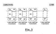
- Filter nach einem der Ansprüche 9 bis 12, dadurch gekennzeichnet, dass es drei zweistufig elliptische und symmetrische Zellen enthält, die nacheinander mit zwei Verbindungsinduktanzen montiert, und in der Schaltung der Abbildung 5 angeordnet sind, wobei die jeweiligen Bauteile die Werte der folgenden Tabelle mit einer Genauigkeit von mehr oder weniger 10% aufweisen:
L1a, Lia' 44,1 µH CT1 12 nF L1b, L1b' 1,6 µH L2a, L2a' 108,9 µH CT2 13,5 nF L2b, L2b' 3,6 µH L3a, L3a' 122,5 µH CT3 15,39 nF L3b, L3b' 2,5 µH L4, L4' 102,4 µH
Applications Claiming Priority (3)
| Application Number | Priority Date | Filing Date | Title |
|---|---|---|---|
| FR0105213 | 2001-04-17 | ||
| FR0105213A FR2823627B1 (fr) | 2001-04-17 | 2001-04-17 | Filtre passe bas a composants uniquement passifs destine au decouplage des voies xdsl |
| PCT/FR2002/001206 WO2002084867A1 (fr) | 2001-04-17 | 2002-04-05 | Filtre passe-bas à composants uniquement passifs destiné au découplage des voies xdsl |
Publications (2)
| Publication Number | Publication Date |
|---|---|
| EP1380104A1 EP1380104A1 (de) | 2004-01-14 |
| EP1380104B1 true EP1380104B1 (de) | 2008-10-08 |
Family
ID=8862404
Family Applications (1)
| Application Number | Title | Priority Date | Filing Date |
|---|---|---|---|
| EP02722394A Expired - Lifetime EP1380104B1 (de) | 2001-04-17 | 2002-04-05 | Tiefpassfilter mit ausschliesslich passiven elementen zur entkopplung der xdsl-übertrangungskanäle |
Country Status (5)
| Country | Link |
|---|---|
| EP (1) | EP1380104B1 (de) |
| AT (1) | ATE410824T1 (de) |
| DE (1) | DE60229226D1 (de) |
| FR (1) | FR2823627B1 (de) |
| WO (1) | WO2002084867A1 (de) |
Families Citing this family (2)
| Publication number | Priority date | Publication date | Assignee | Title |
|---|---|---|---|---|
| FR2857174B1 (fr) * | 2003-07-03 | 2005-09-23 | Europe Adsl Leacom Fastnet Lab | Filtre passe bas pour filtrage de signaux adsl sur des lignes telephoniques |
| FR2873874B1 (fr) * | 2004-07-27 | 2007-01-19 | Microspire Sa | Filtre passe-bas a composants uniquement passifs destine au decouplage de voies basse frequence et haute frequence |
Family Cites Families (3)
| Publication number | Priority date | Publication date | Assignee | Title |
|---|---|---|---|---|
| IL138199A0 (en) * | 1998-03-03 | 2001-10-31 | Vacuumschelze Gmbh | Low-pass filter for a diplexer |
| FR2793633B1 (fr) * | 1999-04-23 | 2002-09-06 | France Telecom | Dispositif de filtrage passe-bas avec isolateur integre et installation privative comportant un tel dispositif |
| WO2001006737A1 (en) * | 1999-07-14 | 2001-01-25 | 2Wire, Inc. | Odd-order low-pass pots device filter |
-
2001
- 2001-04-17 FR FR0105213A patent/FR2823627B1/fr not_active Expired - Fee Related
-
2002
- 2002-04-05 EP EP02722394A patent/EP1380104B1/de not_active Expired - Lifetime
- 2002-04-05 WO PCT/FR2002/001206 patent/WO2002084867A1/fr not_active Ceased
- 2002-04-05 AT AT02722394T patent/ATE410824T1/de not_active IP Right Cessation
- 2002-04-05 DE DE60229226T patent/DE60229226D1/de not_active Expired - Lifetime
Non-Patent Citations (1)
| Title |
|---|
| DIETER NÜHRMANN: "Das grosse Werkbuch Elektronik", 31 December 1994, FRANZIS-VERLAG GMBH, POING, ISBN: 3-7723-6546-9 * |
Also Published As
| Publication number | Publication date |
|---|---|
| DE60229226D1 (de) | 2008-11-20 |
| FR2823627A1 (fr) | 2002-10-18 |
| ATE410824T1 (de) | 2008-10-15 |
| WO2002084867A1 (fr) | 2002-10-24 |
| FR2823627B1 (fr) | 2003-08-22 |
| EP1380104A1 (de) | 2004-01-14 |
Similar Documents
| Publication | Publication Date | Title |
|---|---|---|
| US6963559B2 (en) | Arrangement of local area network | |
| EP1142291A2 (de) | Filterung von netzdaten | |
| EP1380104B1 (de) | Tiefpassfilter mit ausschliesslich passiven elementen zur entkopplung der xdsl-übertrangungskanäle | |
| CN101150303A (zh) | 用于电信系统中的xDSL分路器的多阶低通滤波器 | |
| EP1566050B1 (de) | Tiefpassfilter für telefonleitungen mit adsl-übertragung | |
| EP1470641B1 (de) | Tiefpassfilteranordnung zur entkopplung von xdsl kanälen | |
| EP1645031B1 (de) | Tiefpassfilter zur filterung von adsl-signalen auf telefonleitungen | |
| EP1632084B1 (de) | Impedanzadapter für einen übertragungskanal mit hoher bandbreite eines kupferverdrahteten terminal-systems | |
| WO2001008305A1 (en) | Filter arrangement and method for frequency filtering and impedance conversion | |
| EP1493228B1 (de) | Anwendungsspezifische integrierte schaltung für eine zum entkoppeln von xdsl-kanälen verwendete tiefpassfiltereinrichtung | |
| JP4362256B2 (ja) | Adsl周波数分離回路網 | |
| JP2000165553A (ja) | スプリッタ回路 | |
| TWI481249B (zh) | 用於分離語音訊號與數據訊號之分離器 | |
| US8558642B2 (en) | Splitter circuits for separating signals | |
| EP1260091B1 (de) | Abzweigfilter für datenübertragungsstrecke | |
| EP1339209A1 (de) | Tiefpassfilter für Telefonleitungen mit ADSL-Übertragung | |
| US20030190039A1 (en) | Saturable core POTS/DSL filter | |
| US10079645B2 (en) | Optical telecommunications devices, systems, and methods | |
| CN207425509U (zh) | 一种G.fast薄线圈结构 | |
| FR2855680A1 (fr) | Filtre passe bas pour filtrage de signaux adsl sur des lignes telephoniques modelisees par une impedance complexe | |
| JP2004007549A (ja) | 信号処理装置 | |
| FR2873874A1 (fr) | Filtre passe-bas a composants uniquement passifs destine au decouplage de voies basse frequence et haute frequence | |
| US20040135651A1 (en) | Filter arragement | |
| CN101427464A (zh) | 用于在开关应用中使用的电子滤波器和电路 | |
| FR2834856A1 (fr) | Dispositif de filtrage passe-bas avec dispositif d'isolation et circuit de derivation |
Legal Events
| Date | Code | Title | Description |
|---|---|---|---|
| PUAI | Public reference made under article 153(3) epc to a published international application that has entered the european phase |
Free format text: ORIGINAL CODE: 0009012 |
|
| 17P | Request for examination filed |
Effective date: 20031110 |
|
| AK | Designated contracting states |
Kind code of ref document: A1 Designated state(s): AT BE CH CY DE DK ES FI FR GB GR IE IT LI LU MC NL PT SE TR |
|
| AX | Request for extension of the european patent |
Extension state: AL LT LV MK RO SI |
|
| RAP1 | Party data changed (applicant data changed or rights of an application transferred) |
Owner name: LABORATOIRE EUROPEEN ADSL |
|
| 17Q | First examination report despatched |
Effective date: 20061109 |
|
| GRAP | Despatch of communication of intention to grant a patent |
Free format text: ORIGINAL CODE: EPIDOSNIGR1 |
|
| GRAS | Grant fee paid |
Free format text: ORIGINAL CODE: EPIDOSNIGR3 |
|
| GRAA | (expected) grant |
Free format text: ORIGINAL CODE: 0009210 |
|
| AK | Designated contracting states |
Kind code of ref document: B1 Designated state(s): AT BE CH CY DE DK ES FI FR GB GR IE IT LI LU MC NL PT SE TR |
|
| REG | Reference to a national code |
Ref country code: GB Ref legal event code: FG4D Free format text: NOT ENGLISH |
|
| REG | Reference to a national code |
Ref country code: CH Ref legal event code: EP |
|
| REG | Reference to a national code |
Ref country code: IE Ref legal event code: FG4D Free format text: LANGUAGE OF EP DOCUMENT: FRENCH |
|
| REF | Corresponds to: |
Ref document number: 60229226 Country of ref document: DE Date of ref document: 20081120 Kind code of ref document: P |
|
| NLV1 | Nl: lapsed or annulled due to failure to fulfill the requirements of art. 29p and 29m of the patents act | ||
| PG25 | Lapsed in a contracting state [announced via postgrant information from national office to epo] |
Ref country code: AT Free format text: LAPSE BECAUSE OF FAILURE TO SUBMIT A TRANSLATION OF THE DESCRIPTION OR TO PAY THE FEE WITHIN THE PRESCRIBED TIME-LIMIT Effective date: 20081008 Ref country code: ES Free format text: LAPSE BECAUSE OF FAILURE TO SUBMIT A TRANSLATION OF THE DESCRIPTION OR TO PAY THE FEE WITHIN THE PRESCRIBED TIME-LIMIT Effective date: 20090119 |
|
| PG25 | Lapsed in a contracting state [announced via postgrant information from national office to epo] |
Ref country code: PT Free format text: LAPSE BECAUSE OF FAILURE TO SUBMIT A TRANSLATION OF THE DESCRIPTION OR TO PAY THE FEE WITHIN THE PRESCRIBED TIME-LIMIT Effective date: 20090218 Ref country code: FI Free format text: LAPSE BECAUSE OF FAILURE TO SUBMIT A TRANSLATION OF THE DESCRIPTION OR TO PAY THE FEE WITHIN THE PRESCRIBED TIME-LIMIT Effective date: 20081008 Ref country code: NL Free format text: LAPSE BECAUSE OF FAILURE TO SUBMIT A TRANSLATION OF THE DESCRIPTION OR TO PAY THE FEE WITHIN THE PRESCRIBED TIME-LIMIT Effective date: 20081008 |
|
| REG | Reference to a national code |
Ref country code: IE Ref legal event code: FD4D |
|
| PG25 | Lapsed in a contracting state [announced via postgrant information from national office to epo] |
Ref country code: DK Free format text: LAPSE BECAUSE OF FAILURE TO SUBMIT A TRANSLATION OF THE DESCRIPTION OR TO PAY THE FEE WITHIN THE PRESCRIBED TIME-LIMIT Effective date: 20081008 Ref country code: IE Free format text: LAPSE BECAUSE OF FAILURE TO SUBMIT A TRANSLATION OF THE DESCRIPTION OR TO PAY THE FEE WITHIN THE PRESCRIBED TIME-LIMIT Effective date: 20081008 |
|
| PLBE | No opposition filed within time limit |
Free format text: ORIGINAL CODE: 0009261 |
|
| STAA | Information on the status of an ep patent application or granted ep patent |
Free format text: STATUS: NO OPPOSITION FILED WITHIN TIME LIMIT |
|
| PG25 | Lapsed in a contracting state [announced via postgrant information from national office to epo] |
Ref country code: SE Free format text: LAPSE BECAUSE OF FAILURE TO SUBMIT A TRANSLATION OF THE DESCRIPTION OR TO PAY THE FEE WITHIN THE PRESCRIBED TIME-LIMIT Effective date: 20090108 Ref country code: IT Free format text: LAPSE BECAUSE OF FAILURE TO SUBMIT A TRANSLATION OF THE DESCRIPTION OR TO PAY THE FEE WITHIN THE PRESCRIBED TIME-LIMIT Effective date: 20081008 |
|
| 26N | No opposition filed |
Effective date: 20090709 |
|
| REG | Reference to a national code |
Ref country code: CH Ref legal event code: PL |
|
| GBPC | Gb: european patent ceased through non-payment of renewal fee |
Effective date: 20090405 |
|
| PG25 | Lapsed in a contracting state [announced via postgrant information from national office to epo] |
Ref country code: CH Free format text: LAPSE BECAUSE OF NON-PAYMENT OF DUE FEES Effective date: 20090430 Ref country code: LI Free format text: LAPSE BECAUSE OF NON-PAYMENT OF DUE FEES Effective date: 20090430 |
|
| PG25 | Lapsed in a contracting state [announced via postgrant information from national office to epo] |
Ref country code: GB Free format text: LAPSE BECAUSE OF NON-PAYMENT OF DUE FEES Effective date: 20090405 Ref country code: MC Free format text: LAPSE BECAUSE OF NON-PAYMENT OF DUE FEES Effective date: 20090430 |
|
| PG25 | Lapsed in a contracting state [announced via postgrant information from national office to epo] |
Ref country code: GR Free format text: LAPSE BECAUSE OF FAILURE TO SUBMIT A TRANSLATION OF THE DESCRIPTION OR TO PAY THE FEE WITHIN THE PRESCRIBED TIME-LIMIT Effective date: 20090109 |
|
| PG25 | Lapsed in a contracting state [announced via postgrant information from national office to epo] |
Ref country code: LU Free format text: LAPSE BECAUSE OF NON-PAYMENT OF DUE FEES Effective date: 20090405 |
|
| PG25 | Lapsed in a contracting state [announced via postgrant information from national office to epo] |
Ref country code: TR Free format text: LAPSE BECAUSE OF FAILURE TO SUBMIT A TRANSLATION OF THE DESCRIPTION OR TO PAY THE FEE WITHIN THE PRESCRIBED TIME-LIMIT Effective date: 20081008 |
|
| PG25 | Lapsed in a contracting state [announced via postgrant information from national office to epo] |
Ref country code: CY Free format text: LAPSE BECAUSE OF FAILURE TO SUBMIT A TRANSLATION OF THE DESCRIPTION OR TO PAY THE FEE WITHIN THE PRESCRIBED TIME-LIMIT Effective date: 20081008 |
|
| PGFP | Annual fee paid to national office [announced via postgrant information from national office to epo] |
Ref country code: DE Payment date: 20120529 Year of fee payment: 11 |
|
| PGFP | Annual fee paid to national office [announced via postgrant information from national office to epo] |
Ref country code: BE Payment date: 20120529 Year of fee payment: 11 |
|
| BERE | Be: lapsed |
Owner name: LABORATOIRE EUROPEEN ADSL Effective date: 20130430 |
|
| PG25 | Lapsed in a contracting state [announced via postgrant information from national office to epo] |
Ref country code: DE Free format text: LAPSE BECAUSE OF NON-PAYMENT OF DUE FEES Effective date: 20131101 Ref country code: BE Free format text: LAPSE BECAUSE OF NON-PAYMENT OF DUE FEES Effective date: 20130430 |
|
| REG | Reference to a national code |
Ref country code: DE Ref legal event code: R119 Ref document number: 60229226 Country of ref document: DE Effective date: 20131101 |
|
| REG | Reference to a national code |
Ref country code: FR Ref legal event code: PLFP Year of fee payment: 15 |
|
| REG | Reference to a national code |
Ref country code: FR Ref legal event code: PLFP Year of fee payment: 16 |
|
| REG | Reference to a national code |
Ref country code: FR Ref legal event code: PLFP Year of fee payment: 17 |
|
| PGFP | Annual fee paid to national office [announced via postgrant information from national office to epo] |
Ref country code: FR Payment date: 20210323 Year of fee payment: 20 |