EP1379089A1 - Image encoding method and apparatus, image decoding method and apparatus, and image processing system - Google Patents
Image encoding method and apparatus, image decoding method and apparatus, and image processing system Download PDFInfo
- Publication number
- EP1379089A1 EP1379089A1 EP02714540A EP02714540A EP1379089A1 EP 1379089 A1 EP1379089 A1 EP 1379089A1 EP 02714540 A EP02714540 A EP 02714540A EP 02714540 A EP02714540 A EP 02714540A EP 1379089 A1 EP1379089 A1 EP 1379089A1
- Authority
- EP
- European Patent Office
- Prior art keywords
- image
- waveform
- information
- encoding
- signal
- Prior art date
- Legal status (The legal status is an assumption and is not a legal conclusion. Google has not performed a legal analysis and makes no representation as to the accuracy of the status listed.)
- Withdrawn
Links
Images





Classifications
-
- G—PHYSICS
- G06—COMPUTING OR CALCULATING; COUNTING
- G06T—IMAGE DATA PROCESSING OR GENERATION, IN GENERAL
- G06T9/00—Image coding
- G06T9/008—Vector quantisation
-
- H—ELECTRICITY
- H04—ELECTRIC COMMUNICATION TECHNIQUE
- H04N—PICTORIAL COMMUNICATION, e.g. TELEVISION
- H04N19/00—Methods or arrangements for coding, decoding, compressing or decompressing digital video signals
- H04N19/10—Methods or arrangements for coding, decoding, compressing or decompressing digital video signals using adaptive coding
- H04N19/102—Methods or arrangements for coding, decoding, compressing or decompressing digital video signals using adaptive coding characterised by the element, parameter or selection affected or controlled by the adaptive coding
- H04N19/103—Selection of coding mode or of prediction mode
- H04N19/107—Selection of coding mode or of prediction mode between spatial and temporal predictive coding, e.g. picture refresh
-
- H—ELECTRICITY
- H04—ELECTRIC COMMUNICATION TECHNIQUE
- H04N—PICTORIAL COMMUNICATION, e.g. TELEVISION
- H04N19/00—Methods or arrangements for coding, decoding, compressing or decompressing digital video signals
- H04N19/10—Methods or arrangements for coding, decoding, compressing or decompressing digital video signals using adaptive coding
- H04N19/134—Methods or arrangements for coding, decoding, compressing or decompressing digital video signals using adaptive coding characterised by the element, parameter or criterion affecting or controlling the adaptive coding
- H04N19/146—Data rate or code amount at the encoder output
- H04N19/152—Data rate or code amount at the encoder output by measuring the fullness of the transmission buffer
-
- H—ELECTRICITY
- H04—ELECTRIC COMMUNICATION TECHNIQUE
- H04N—PICTORIAL COMMUNICATION, e.g. TELEVISION
- H04N19/00—Methods or arrangements for coding, decoding, compressing or decompressing digital video signals
- H04N19/10—Methods or arrangements for coding, decoding, compressing or decompressing digital video signals using adaptive coding
- H04N19/169—Methods or arrangements for coding, decoding, compressing or decompressing digital video signals using adaptive coding characterised by the coding unit, i.e. the structural portion or semantic portion of the video signal being the object or the subject of the adaptive coding
- H04N19/17—Methods or arrangements for coding, decoding, compressing or decompressing digital video signals using adaptive coding characterised by the coding unit, i.e. the structural portion or semantic portion of the video signal being the object or the subject of the adaptive coding the unit being an image region, e.g. an object
- H04N19/172—Methods or arrangements for coding, decoding, compressing or decompressing digital video signals using adaptive coding characterised by the coding unit, i.e. the structural portion or semantic portion of the video signal being the object or the subject of the adaptive coding the unit being an image region, e.g. an object the region being a picture, frame or field
-
- H—ELECTRICITY
- H04—ELECTRIC COMMUNICATION TECHNIQUE
- H04N—PICTORIAL COMMUNICATION, e.g. TELEVISION
- H04N19/00—Methods or arrangements for coding, decoding, compressing or decompressing digital video signals
- H04N19/10—Methods or arrangements for coding, decoding, compressing or decompressing digital video signals using adaptive coding
- H04N19/169—Methods or arrangements for coding, decoding, compressing or decompressing digital video signals using adaptive coding characterised by the coding unit, i.e. the structural portion or semantic portion of the video signal being the object or the subject of the adaptive coding
- H04N19/1883—Methods or arrangements for coding, decoding, compressing or decompressing digital video signals using adaptive coding characterised by the coding unit, i.e. the structural portion or semantic portion of the video signal being the object or the subject of the adaptive coding the unit relating to sub-band structure, e.g. hierarchical level, directional tree, e.g. low-high [LH], high-low [HL], high-high [HH]
-
- H—ELECTRICITY
- H04—ELECTRIC COMMUNICATION TECHNIQUE
- H04N—PICTORIAL COMMUNICATION, e.g. TELEVISION
- H04N19/00—Methods or arrangements for coding, decoding, compressing or decompressing digital video signals
- H04N19/30—Methods or arrangements for coding, decoding, compressing or decompressing digital video signals using hierarchical techniques, e.g. scalability
-
- H—ELECTRICITY
- H04—ELECTRIC COMMUNICATION TECHNIQUE
- H04N—PICTORIAL COMMUNICATION, e.g. TELEVISION
- H04N19/00—Methods or arrangements for coding, decoding, compressing or decompressing digital video signals
- H04N19/60—Methods or arrangements for coding, decoding, compressing or decompressing digital video signals using transform coding
- H04N19/61—Methods or arrangements for coding, decoding, compressing or decompressing digital video signals using transform coding in combination with predictive coding
-
- H—ELECTRICITY
- H04—ELECTRIC COMMUNICATION TECHNIQUE
- H04N—PICTORIAL COMMUNICATION, e.g. TELEVISION
- H04N19/00—Methods or arrangements for coding, decoding, compressing or decompressing digital video signals
- H04N19/60—Methods or arrangements for coding, decoding, compressing or decompressing digital video signals using transform coding
- H04N19/63—Methods or arrangements for coding, decoding, compressing or decompressing digital video signals using transform coding using sub-band based transform, e.g. wavelets
-
- H—ELECTRICITY
- H04—ELECTRIC COMMUNICATION TECHNIQUE
- H04N—PICTORIAL COMMUNICATION, e.g. TELEVISION
- H04N19/00—Methods or arrangements for coding, decoding, compressing or decompressing digital video signals
- H04N19/60—Methods or arrangements for coding, decoding, compressing or decompressing digital video signals using transform coding
- H04N19/63—Methods or arrangements for coding, decoding, compressing or decompressing digital video signals using transform coding using sub-band based transform, e.g. wavelets
- H04N19/64—Methods or arrangements for coding, decoding, compressing or decompressing digital video signals using transform coding using sub-band based transform, e.g. wavelets characterised by ordering of coefficients or of bits for transmission
-
- H—ELECTRICITY
- H04—ELECTRIC COMMUNICATION TECHNIQUE
- H04N—PICTORIAL COMMUNICATION, e.g. TELEVISION
- H04N19/00—Methods or arrangements for coding, decoding, compressing or decompressing digital video signals
- H04N19/90—Methods or arrangements for coding, decoding, compressing or decompressing digital video signals using coding techniques not provided for in groups H04N19/10-H04N19/85, e.g. fractals
- H04N19/97—Matching pursuit coding
-
- H—ELECTRICITY
- H04—ELECTRIC COMMUNICATION TECHNIQUE
- H04N—PICTORIAL COMMUNICATION, e.g. TELEVISION
- H04N19/00—Methods or arrangements for coding, decoding, compressing or decompressing digital video signals
- H04N19/10—Methods or arrangements for coding, decoding, compressing or decompressing digital video signals using adaptive coding
- H04N19/102—Methods or arrangements for coding, decoding, compressing or decompressing digital video signals using adaptive coding characterised by the element, parameter or selection affected or controlled by the adaptive coding
- H04N19/115—Selection of the code volume for a coding unit prior to coding
-
- H—ELECTRICITY
- H04—ELECTRIC COMMUNICATION TECHNIQUE
- H04N—PICTORIAL COMMUNICATION, e.g. TELEVISION
- H04N19/00—Methods or arrangements for coding, decoding, compressing or decompressing digital video signals
- H04N19/10—Methods or arrangements for coding, decoding, compressing or decompressing digital video signals using adaptive coding
- H04N19/102—Methods or arrangements for coding, decoding, compressing or decompressing digital video signals using adaptive coding characterised by the element, parameter or selection affected or controlled by the adaptive coding
- H04N19/124—Quantisation
-
- H—ELECTRICITY
- H04—ELECTRIC COMMUNICATION TECHNIQUE
- H04N—PICTORIAL COMMUNICATION, e.g. TELEVISION
- H04N19/00—Methods or arrangements for coding, decoding, compressing or decompressing digital video signals
- H04N19/10—Methods or arrangements for coding, decoding, compressing or decompressing digital video signals using adaptive coding
- H04N19/134—Methods or arrangements for coding, decoding, compressing or decompressing digital video signals using adaptive coding characterised by the element, parameter or criterion affecting or controlling the adaptive coding
- H04N19/146—Data rate or code amount at the encoder output
Definitions
- the present invention relates to an image encoding and decoding method for encoding a source image such as a moving image and a still image and decoding the encoded image and, more particularly, to an image encoding method, an image encoder, an image decoding method and an image decoder that can encode an image and decode the encoded image with no use of DCT (discrete cosine transform) employed in standard algorithms of MPEG series and so on.
- DCT discrete cosine transform
- the present invention relates to an image processing system that encodes and decodes an image in accordance with such an image encoding method and an image decoding method.
- DCT discrete cosine transform
- ITU-T H.26x and MPEG series DCT (discrete cosine transform) is used as a means to decrease spatial redundancy.
- the DCT performs an orthogonal transform for a block formed of 8 ⁇ 8 pixels in an image signal space, decomposes an image signal of a source image into a predetermined combination of bases, and obtains coefficients of the bases.
- the DCT has a characteristic of increasing the coefficient values, that is, a degree of bias with respect to a frequency component. Since the DCT especially concentrates the bias on a low frequency level that plays an important role in vision, the DCT can enhance compression efficiency by performing an adaptive bit distribution.
- a large number of bases are required to faithfully reconstruct a steep luminance fluctuation such as a step edge and a portion of waveform having a random pattern.
- a code assignment for a coefficient corresponding to a high frequency level is weighted less than a low frequency level.
- the coefficient in the high frequency which plays an important role in reconstructing the waveform, is lost.
- the loss of the coefficient causes harmful noise peculiar to the DCT and results in image quality degradation.
- the quality hierarchical encoding technique is a technique such that an encoding distortion generated in an encoding picture in a base layer is separately encoded as an enhance layer and a decoding side sums signals obtained by decoding individual layers so as to enhance the quality of a decoded image.
- the quality hierarchical encoding technique the necessary number of transmission bits increases by an amount of encoding data in the enhance layer.
- the quality hierarchical encoding technique is favorable for a picture transmission required to accommodate flexibly to a network such as the Internet and a wireless network whose transmission condition (bit rate, packet loss probability, error rate and so on) varies over time.
- the DCT is further performed for an encoding error signal in the enhance layer and the resulting coefficients are transmitted per bit plane, it is possible to transmit a picture in a manner such that the picture quality is gradually improving in the decoding side as its name suggests.
- the enhance layer still depends on the DCT and the DCT block structure, and a distortion component depending upon the block structure, which shows up in an encoding distortion component in the base layer, generates high order DCT coefficients. As a result, if little information is used in the enhance layer, the encoding does not work efficiently.
- the present invention is an image encoding method, comprising: a pattern matching step searching for a waveform vector similar to a partial signal waveform of an image signal in a predetermined group of waveform vectors; and a waveform pattern encoding step performing a compression encoding for information to identify the waveform vector searched for, similarity information to represent similarity between the partial signal waveform and the waveform vector searched for, and a position in an image of the partial signal waveform in accordance with a predetermined encoding rule, wherein the image signal is encoded from a combination of the information to identify the waveform vector, the similarity information and the position in the image of the partial signal waveform, and wherein the position in the image of the partial signal waveform is encoded through replacement with position information in a predetermined partial domain of the image signal.
- the above-mentioned image signal may be a signal representing a moving image or a signal representing a still image. Also, the image signal may be any additional information that is helpful for a process to encode or decode the signals.
- the similarity information representing the similarity between the partial signal waveform and the waveform vector is not limited as long as the information is a parameter representing the similarity.
- the inner product of the partial signal waveform and the waveform vector may be used.
- the present invention is an image encoding method, comprising: a pattern matching step searching for a waveform vector in a predetermined group of waveform vectors based upon inner products of the waveform vectors and a partial signal waveform of an image signal; and a waveform pattern encoding step performing a compression encoding for information to identify the waveform vector searched for, an inner product value of the partial signal waveform and the waveform vector searched for, and a position in an image of the partial signal waveform in accordance with a predetermined encoding rule, wherein in a process in which the pattern matching step and the waveform pattern encoding step are iterated until a predetermined condition is satisfied, whenever encoding information is obtained at the waveform pattern encoding step, a reconstructed waveform of a partial signal waveform obtained from the encoding information is subtracted from the image signal so as to produce an image signal to be provided to the pattern matching step, and the image signal is encoded according to the encoding information obtained at the waveform pattern step
- pixels formed of a predetermined power of 2 ⁇ 2 of an image signal represented by a predetermined pixel unit may be set as a unit, and a position in an image of a partial signal waveform to be encoded may be identified.
- the predetermined partial domain may be divided into unit blocks to identify a position and may be stratified in a block domain formed of one unit block or a plurality of unit blocks based upon an inclusive relation, and the position in the image of the partial signal waveform may be encoded based upon a sequence of bits indicating whether or not each block domain of an individual layer includes a position of a partial signal waveform to obtain an inner product value of the partial signal waveform and a waveform pattern in a group of waveform patterns.
- the image signal to be processed may be information representing a source image to be encoded.
- the image signal to be processed may be information representing a prediction residual image obtained by performing a motion compensation prediction for a source image to be processed.
- the image signal to be processed may be an encoding distortion signal generated by encoding a source image in accordance with a predetermined encoding rule.
- the image signal to be processed may be information representing a prediction residual image obtained by performing a motion compensation prediction for an encoding distortion signal generated by encoding a source image in accordance with a predetermined encoding rule.
- an image encoder comprises: a pattern matching part searching for a waveform vector similar to a partial signal waveform of an image signal in a predetermined group of waveform vectors; and a waveform pattern encoding part performing a compression encoding for information to identify the waveform vector searched for, similarity information to represent similarity between the partial signal waveform and the waveform vector searched for, and a position in an image of the partial signal waveform in accordance with a predetermined encoding rule, wherein the image signal is encoded from a combination of the information to identify the waveform vector, the similarity information and the position in the image of the partial signal waveform, and wherein the waveform pattern encoding part encodes the position in the image of the partial signal waveform through replacement with information regarding position in a predetermined partial domain of the image signal.
- an image encoder comprises: a pattern matching part searching for a waveform vector in a predetermined group of waveform vectors based upon inner products of the waveform vectors and a partial signal waveform of an image signal; and a waveform pattern encoding part performing a compression encoding for information to identify the searched waveform vector, an inner product value of the partial signal waveform and the waveform vector searched for, and a position in an image of the partial signal waveform in accordance with a predetermined encoding rule, wherein in a process in which operations on the pattern matching part and the waveform pattern encoding part are iterated until a predetermined condition is satisfied, whenever encoding information is obtained at the waveform pattern encoding part, a reconstructed waveform of a partial signal waveform obtained from the encoding information is subtracted from the image signal so as to produce an image signal to be provided to the pattern matching part, and the image signal is encoded according to the encoding
- the present invention is an image encoding method, comprising: a first image encoding step performing a compression encoding for a first image signal per predetermined partial domain in accordance with a first encoding rule; and a second image encoding step performing a compression encoding for a second image signal per partial signal waveform of the second image signal in accordance with a second encoding rule, wherein a signal corresponding to an error signal between a first image signal provided to the first encoding step and a signal obtained by performing a local decoding process for encoding information obtained at the first image encoding step is set as a second image signal provided to the second image encoding step, and wherein the second image encoding step comprises: a pattern matching step searching for a waveform vector similar to a partial signal waveform of the second image signal in a predetermined group of waveform vectors; and a waveform pattern encoding step performing a compression encoding for information to identify
- a group of waveform vectors to be used is selected among a plurality of groups of waveform vectors based upon the parameter used for performing an encoding at the first image encoding step and the position in the second image of the partial waveform signal.
- the second image information is a signal corresponding to an error signal between a first image signal provided to the first encoding step and a signal obtained by performing a local decoding process for encoding information obtained at the first image encoding step.
- the first image information provided to the first image encoding step is assumed to be a source image
- the second image information corresponds to an encoding distortion signal generated by encoding the source image.
- the present invention is an image encoding method, comprising: a first image encoding step performing a compression encoding for a first image signal per predetermined partial domain in accordance with a first encoding rule; and a second image encoding step performing a compression encoding for a second image signal per partial signal waveform of the second image signal in accordance with a second encoding rule, wherein a signal corresponding to an error signal between a first image signal provided to the first encoding step and a signal obtained by performing a local decoding process for encoding information obtained at the first image encoding step is set as a second image signal provided to the second image encoding step, and wherein the second image encoding step comprises a pattern matching step searching for a waveform vector in a predetermined group of waveform vectors based upon inner products of the waveform vectors and a partial signal waveform of
- an image encoder that operates a process in accordance with the above-mentioned image encoding method, comprises: a first image encoding part performing a compression encoding for a first image signal per predetermined partial domain in accordance with a first encoding rule; and a second image encoding part performing a compression encoding for a second image signal per partial signal waveform of the second image signal in accordance with a second encoding rule, wherein a signal corresponding to an error signal between a first image signal provided to the first encoding part and a signal obtained by performing a local decoding process for encoding information obtained by the first image encoding part is set as a second image signal provided to the second image encoding part, and wherein the second image encoding part comprises: a pattern matching part searching for a waveform vector similar to a partial signal waveform of the second image signal in a predetermined group of waveform vectors; and a waveform pattern encoding part performing a compression encoding for information to identify
- the present invention is an image encoder, comprising: a first image encoding part performing a compression encoding for a first image signal per predetermined partial domain in accordance with a first encoding rule; and a second image encoding part performing a compression encoding for a second image signal per partial signal waveform of the second image signal in accordance with a second encoding rule, wherein a signal corresponding to an error signal between a first image signal provided to the first encoding part and a signal obtained by performing a local decoding process for encoding information obtained by the first image encoding part is set as a second image signal provided to the second image encoding part, and wherein the second image encoding part comprises a pattern matching part searching for a waveform vector in a predetermined group of waveform vectors based upon inner products of the waveform vectors and a partial signal waveform of the second image signal; and a waveform pattern encoding part performing a compression encoding for information to identify the waveform vector
- the present invention is an image decoding method for receiving compressed image information and reconstructing image information by decompressing the compressed image information per predetermined partial domain
- the image decoding method comprising the steps of: decoding compressed image information regarding a predetermined partial domain in accordance with a predetermined decoding rule and obtaining information to identify a waveform vector, similarity information to represent similarity between a partial signal waveform and the waveform vector, and a position in an image of the partial signal waveform; reconstructing image information based upon the waveform vector identified from a predetermined group of waveform vectors by the information to identify a waveform vector, the similarity information, and the position in the image of the partial signal waveform; and decoding the position in the image of the partial signal waveform included in the compressed image information as information per predetermined partial image domain when the compressed image information is decoded.
- the present invention is an image decoding method for receiving compressed image information and reconstructing image information by decompressing the compressed image information per predetermined partial domain
- the image decoding method comprising the steps of: decoding compressed image information regarding a predetermined partial domain in accordance with a predetermined decoding rule and obtaining information to identify a waveform vector, an inner product value of the waveform vector and a partial signal waveform, and a position in an image of the partial signal waveform; reconstructing image information based upon the waveform vector identified from a predetermined group of waveform vectors by the information to identify a waveform vector, the inner product value, and the position in the image of the partial signal waveform; and decoding the position in the image of the partial signal waveform included in the compressed image information as information per predetermined partial image domain when the compressed image information is decoded.
- an image decoder that operates a process in accordance with the above-mentioned image decoding method, for receiving compressed image information and reconstructing image information by decompressing the compressed image information per predetermined partial domain, comprises: a first part decoding compressed image information regarding a predetermined partial domain in accordance with a predetermined decoding rule and obtaining information to identify a waveform vector, similarity information to represent similarity between a partial signal waveform and the waveform vector, and a position in an image of the partial signal waveform; and a second part reconstructing image information based upon the waveform vector identified from a predetermined group of waveform vectors by the information to identify a waveform vector, the similarity information, and the position in the image of the partial signal waveform, wherein the first part decodes the position in the image of the partial signal waveform included in the compressed image information as information per predetermined partial image domain when the compressed image information is decoded.
- the present invention is an image decoder for receiving compressed image information and reconstructing image information by decompressing the compressed image information per predetermined partial domain, comprising: a first part decoding compressed image information regarding a predetermined partial domain in accordance with a predetermined decoding rule and obtaining information to identify a waveform vector, an inner product value of the waveform vector and a partial signal waveform, and a position in an image of the partial signal waveform; and a second part reconstructing image information based upon the waveform vector identified by the information to identify the waveform vector from a predetermined group of waveform vectors, the inner product value, and the position in the image of the partial signal waveform, wherein the first part decodes the position in the image of the partial signal waveform included in the compressed image information as information per predetermined partial image domain when the compressed image information is decoded.
- the present invention is an image decoding method, comprising: a first image decoding step receiving a first compressed image and reconstructing a first image information by decompressing the first compressed image information per predetermined partial domain; a second image decoding step receiving a second compressed image and reconstructing a second image information by decompressing the second compressed image information per predetermined partial signal waveform; and an image synthesizing step obtaining output image information by synthesizing the first image information and the second image information, wherein in the second image decoding step, by decoding the second compressed image information in accordance with a predetermined decoding rule, information to identify a waveform vector, similarity information to represent similarity between a partial signal waveform and the waveform vector, and a position in an image of the partial signal waveform are obtained, and a group of waveform vectors to be used is selected among a plurality of predetermined groups of waveform vectors based upon a code parameter included in the first compressed image information provided to the first image decoding step and the position in the
- the present invention is an image decoding method, comprising: a first image decoding step receiving a first compressed image and reconstructing a first image information by decompressing the first compressed image information per predetermined partial domain; a second image decoding step receiving a second compressed image and reconstructing a second image information by decompressing the second compressed image information per predetermined partial signal waveform; and an image synthesizing step obtaining output image information by synthesizing the first image information and the second image information, wherein in the second image decoding step, by decoding the second compressed image information in accordance with a predetermined decoding rule, information to identify a waveform vector, an inner product value of the waveform vector and a partial signal waveform, and a position in an image of the partial signal waveform are obtained, and a group of waveform vectors to be used is selected among a plurality of predetermined groups of waveform vectors based upon a code parameter included in the first compressed image information provided to the first image decoding step and the position in the image of the
- an image decoder that operates a process in accordance with the above-mentioned image decoding method, comprises: a first image decoding part receiving a first compressed image and reconstructing a first image information by decompressing the first compressed image information per predetermined partial domain; a second image decoding part receiving a second compressed image and reconstructing a second image information by decompressing the second compressed image information per predetermined partial signal waveform; and an image synthesizing part obtaining output image information by synthesizing the first image information and the second image information, wherein the second image decoding part comprises a plurality of predetermined groups of waveform vectors; a first part decoding the second compressed image information in accordance with a predetermined decoding rule and obtaining information to identify a waveform vector, similarity information to represent similarity between a partial signal waveform and the waveform vector, and a position in an image of the partial signal waveform; a second part selecting a group of waveform vectors to be used among a plurality of predetermined groups of
- the present invention is an image decoder, comprising: a first image decoding part receiving a first compressed image and reconstructing a first image information by decompressing the first compressed image information per predetermined partial domain; a second image decoding part receiving a second compressed image and reconstructing a second image information by decompressing the second compressed image information per predetermined partial signal waveform; and an image synthesizing part obtaining output image information by synthesizing the first image information and the second image information, wherein the second image decoding part comprises a plurality of predetermined groups of waveform vectors; a first part decoding the second compressed image information in accordance with a predetermined decoding rule and obtaining information to identify a waveform vector, an inner product value of a partial signal waveform and the waveform vector, and a position in an image of the partial signal waveform; a second part selecting a group of waveform vectors to be used among a plurality of predetermined groups of waveform vectors based upon a code parameter included in the first compressed image information
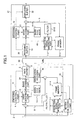
- an image encoder and an image decoder according to the first embodiment of the present invention are constructed as is shown in FIG. 1.
- the "Matching Pursuits" (pattern matching) technique is used to perform a single layer picture encoding and decoding.
- an image encoder 2 comprises an encoding control part 4, a rate buffer 5, a prediction signal generating part 7-1, a frame memory 11-1, a motion detecting part 12, a basis searching part 13, a basis code book 14-1, a basis encoding part 15, a basis local decoding part 16 and a filter 23-1.
- an image decoder 17, which is connected with the image encoder 2 via a predetermined line 30, comprises a decoding control part 18, a receiving buffer 19, a basis decoding part 21, a displaying buffer 22, a filter 23-2, a frame memory 11-2, a prediction signal generating part 7-2 and a basis code book 14-2.
- the image encoder 2 performs a compression encoding for an individual frame of a picture signal 1, which is considered to be a unit. Furthermore, each frame is encoded per macroblock formed of 16 pixels ⁇ 16 lines of a luminance signal. The encoded information is multiplexed to a bitstream 3 and is transmitted to the image decoder 17 via the line 30.
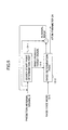
- the encoding process is performed in accordance with a procedure shown in FIG. 2.
- the encoding control part 4 sets initial parameters necessary for performing an encoding together with an acceptable code amount of the frame of interest (initialization: step S1).
- the code parameters include an initial quantization parameter and encoding mode information indicating whether or not the frame is encoded exclusively in the frame or whether or not the frame is encoded by using an inter frame prediction.
- a code amount in the frame mainly depends on the number of pieces of basis information to be encoded (hereinafter, referred to as an atom). The reason will be mentioned later.
- the acceptable code amount in the next frame is set by receiving a feedback of an occupied amount 6 to the encoding control part 4 so that the rate buffer 5 cannot overflow.
- the prediction signal generating part 7-1 generates a prediction image 9 to obtain a prediction residual signal 8 to be encoded (generate prediction image: step S2).
- the prediction image 9 is generated in accordance with a procedure shown in FIG. 4.
- the prediction image 9 is defined per macroblock.
- a macroblock counter n is reset (step S2-1).
- the intra frame prediction is performed for the macroblock n (step S2-2).
- a variety of intra frame prediction methods is assumed. For example, a pixel average of an input macroblock (DC component) may be used as a prediction image. Also, values of marginal pixels of the macroblock that have already been encoded are buffered, and the values may be used to generate a prediction image through a plane prediction.
- a prediction cost incurred by the prediction image data (P_intra) and the intra frame prediction is computed.
- intra frame prediction mode information is also produced to indicate what type of intra frame prediction method has been used.
- a sum of absolute difference (SAD) and a mean square error (MSE) may be used to represent residual power.
- SAD sum of absolute difference
- MSE mean square error
- a code amount-distortion cost representation including additional information required for an adopted prediction method such as above-mentioned intra frame prediction mode information may be used.
- an inter frame prediction is performed by a motion compensation prediction (step S2-3).
- the inter frame prediction identifies a similar image in reference images in the frame memory 11 by predicting a motion between frames and sets the identified similar image as a prediction image.
- the motion detecting part 12 detects a motion vector as information to identify the similar image in the reference images.
- the motion vector may be represented in any form such as a parallel shift vector by block matching often used in existing picture encoding methods, a vector representing an affine model, or a vector representing a perspective transform model. In general, the more complicated a model is and the larger are the number of motions that can be represented, the smaller the prediction residual is.
- any representation is available in this embodiment of the present invention as long as it can be represented as motion information representation having a macroblock as a unit.
- a macroblock may be further divided into smaller blocks and a motion vector may be found for each divided block.
- a plurality of frames may be referred to in order to perform a prediction.
- inter frame prediction mode information is produced to indicate what type of prediction method has been used.
- the inter frame prediction mode may be such a mode that "Matching Pursuits" encoding data of an encoded frame is saved (for the storage, it is required to prepare a memory space to save an atom parameter 24 corresponding to the frame memory 11) and atom information encoded in a reference frame is inherited without change.
- prediction image data (P_inter) a motion vector
- inter frame prediction mode information a prediction cost incurred by a motion compensation prediction
- a prediction cost incurred by a motion compensation prediction the SAD, the MSE and the code amount-distortion cost may be used like the intra frame prediction.
- a code amount which should be considered in the inter frame prediction there are a code amount of the motion vector itself, switch information of a motion vector model, and inter frame prediction mode information and so on.
- step S2-4 it is determined which type of prediction is performed for the macroblock of interest, the intra frame prediction (INTRA) or the inter frame prediction (INTER).
- the two above-mentioned prediction costs are used as an evaluation value with respect to the prediction and the prediction type incurring the smaller prediction cost is chosen.
- a prediction image Pred(n) for the macroblock n is set to a P_intra and the intra frame prediction mode information is output as output information 10 (step S2-5).
- the inter frame prediction (INTER) is chosen, a prediction image Pred(n) is set to a P_inter and the inter frame prediction mode information together with a motion vector is output as the output information 10 (step S2-6).
- the macroblock counter n is incremented (S2-7). If the above-mentioned process is completed for every macroblock in the frame, the prediction image generating process is completed.
- the filter 23-1 suppresses discontinuity in a boundary between blocks caused by the motion detection per macroblock. After that, a difference between the resulting prediction image and the input picture frame 1 is computed and becomes the prediction residual signal 8 to be encoded (generate prediction residual signal: step S3).
- the process on the filter 23-1 prevents any component unnecessary in the "Matching Pursuits" encoding process from being encoded.
- the prediction residual signal 8 generated in the above-mentioned manner is input to the basis searching part 13 and is transformed in the form of a linear combination of basis vectors based upon the "Matching Pursuits” technique (step S4).
- the detailed description of a moving image encoding based upon the "Matching Pursuits” is referred to in "Very Low Bit-rate Video Coding Based on Matching Pursuits” (R.Neff et.al, IEEE Trans. on CSVT, vol.7, pp.158-171, Feb.1997).
- this embodiment of the present invention follows a process mentioned in the above reference.
- the embodiment of the present invention has a characteristic in that the embodiment is designed to efficiently represent the extracted encoding data by using a small amount of code.
- a signal f is represented in the form of a linear combination of a set g k of predetermined over-complete basis functions (waveform patterns) searches for a basis g k such that an inner product of the g k and a signal Rnf (a signal to be represented as a basis at the n searching step: a partial signal waveform) is maximized.
- the signal f is represented as a linear combination such that the linear combination has as its coefficients the inner values where n is the number of basis searching steps, gk is the basis found at the n-th searching step such that the inner product is maximized, and Rmf is a residual component to be searched for at the m-th searching step.
- the representation accuracy of the signal f is enhanced. That means that the larger the number of bases used to represent the signal f, the more accurately the signal f can be represented. Therefore, the larger the number of bases is, that is, the more times of searching steps there are, the more the code amount is and the smaller the distortion is.
- An ideal basis search corresponds to a process for searching for a basis such that for every pixel in a frame, the above inner product is maximized among all predetermined bases (waveform patterns) with respect to a signal waveform whose center is the pixel. For that search, it is necessary to compute enormous arithmetic operations (the number of pixels in a frame) ⁇ (the number of bases) of the inner product.
- the above-mentioned reference proposes a method to detect a domain with high electric power and search for a basis in an area adjacent to the domain.
- FIG. 5 shows a diagram illustrating a detailed structure of the basis searching part 13 according to the embodiment of the present invention.
- the basis searching part 13 comprises a search start point determination part 13-1 and a basis determination part 13-3.
- the search start point determination part 13-1 receives the prediction residual signal 8 as its input and searches for a domain with the maximal electric power in the prediction residual signal 8.
- a position in the searched domain is considered as a start point of the basis search, and image data (partial signal waveform) of an area adjacent to the start point (for example, S pixels ⁇ S lines) is supplied to the basis determination part 13-3 as an inner product arithmetic target signal (Rnf) 13-2.
- the basis determination part 13-3 retrieves individual basis code words 13-4 from the basis code book 14, performs inner product operations of the inner product arithmetic target signal 13-2 and the individual basis code words 13-4, and determines a pair of signal and basis such that the inner product is maximized.
- the basis gk is determined among basis vectors in the basis code book 14.
- the pixel position pn corresponds to a position of the center pixel of Rnf.
- a triple of the code parameters is referred to as an atom.
- the basis determination part 13-3 supplies a signal reconstructed from the atom in accordance with the above formula (1).
- the reconstructed signal is subtracted from the prediction residual signal 8, and then the prediction residual signal is updated for the next searching step.
- the searching step is incremented until the acceptable code amount is reached.
- the atom is determined for each of the searching steps.
- the basis encoding part 15 serves for this encoding operation (step S5).
- a basis index of the atom undergoes a compression encoding operation by means of a variable-length encoding corresponding to emergence frequency of the basis index, and a basis coefficient of the atom undergoes a compression encoding operation by means of a scalar quantization.
- the basis coefficient is quantized in the basis determination part 13-3 in FIG.
- feasable values to the position pn are restricted to multiplicative values of a 2 ⁇ 2 block.
- the center of an atom is always located at a vertex of the 2 ⁇ 2 block, it can be determined per 2 ⁇ 2 block whether or not there is an atom to be encoded.
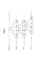
- the image encoder 2 and the image decoder 17 according to the embodiment of the present invention have a bitstream formed of a macroblock with 16 ⁇ 16 pixels as a unit, the information regarding whether or not the atom exists can be described as a four-layer quadrival tree structure whose root is a macroblock as shown in FIG. 6.
- FIG. 7 shows an example of a code representation of the quadrival tree structure.
- the level of the macroblock (16 ⁇ 16) represents by 1 bit just whether there is an atom in an interior of the macroblock (1) or not (0).
- the level of block (8 ⁇ 8) represents by at most 4 bits how atoms are distributed in four 8 ⁇ 8 blocks included in the macroblock.
- the level of block (4 ⁇ 4) and the level of block (2 ⁇ 2) have code representations by at most 16 bits and 64 bits, respectively.
- a vertex having a code "0” not any code has to be assigned for successors of the vertex.
- the quadrival tree may have only one vertex information item.
- atoms often tend to concentrate spatially.
- an optimal variable-length code is designed based upon a conditional probability and an arithmetic code or the like is employed, it is possible to shorten an average code length by assigning a short code length for a tree having many 1s.
- the above-mentioned method By applying the above-mentioned method, it is possible to decrease the number of basis searching points and the arithmetic operations thereof rather than the method to perform a search operation per pixel. Also, the above-mentioned method represents a position of the basis searching point pn as the position in the macroblock by using a tree structure whose root is the macroblock. As a result, whatever display size the image information has, it is possible to fix a maximal code amount required to identify the position of the basis searching point.
- the tree structure makes it possible to represent the position pn of a basis searching point by a lesser code amount and decrease the code amount from a whole frame required to represent the position p n of each basis searching point, if general characteristics of an image are considered.
- step S8 Whenever atoms are encoded for each of the above-mentioned search steps, it is determined at step S8 whether or not the code amount reaches the acceptable code amount. If the code amount reaches the acceptable code amount, the basis searching process is stopped and the encoding of the prediction residual signal of the frame of interest is terminated. Then, if there remain some frames (step S9), the process for the next frame is performed back to step S1. If there is no remaining frame, the process is terminated.
- the bitstream 3 including encoding information generated by the image encoder 2 is supplied to the image decoder 17 via the line 30.
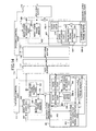
- the image decoder 17 receives the bitstream 3 including the above encoding information and performs the same process as the basis local decoding part 16. In a case in which an image is decoded and displayed in real time, the decoding process is performed in accordance with steps that will be mentioned with respect to FIG. 3.
- a time management function of the decoding control part 18 determines a decoding start time of a frame being at the time t and runs a basis decoding part 21 at the time (step S10).
- the basis decoding part 21 detects a frame synchronous word and analyzes atom data of the bitstream in accordance with a predetermined syntax rule (step S11).
- the prediction signal generating part 7-2 (which performs a process corresponding to the prediction signal generating part 7-1 in the image encoder 2) receives prediction result output information 10 including information regarding a motion vector and a prediction mode in the analyzed data, and then generates a prediction image 9 (step S12).
- An atom decoding process identifies a basis with reference to a basis index and a basis code book 14-2 equivalent to the basis code book 14-1 in the image encoder 2 and reconstructs a prediction residual signal f(x, y) based upon the formula (1) (step S13).
- the position information (ref. FIG 6 and FIG. 7) regarding a macroblock where the basis is applied is transformed into a position in a frame of the prediction residual signal.
- the prediction residual signal f(x, y) is generated by the prediction signal generating part 7-2, is processed by a filter 23-2 and is added as the prediction image 9. Then, a final frame decoding image is generated by using the above position in the frame.
- the decoded image is saved in a displaying buffer 22 (step S14) and is written in the frame memory 11 for the decoding process of the next frame.
- the displaying buffer 22 may be provided to use a portion of a frame memory 11-2.
- the decoding control part 18 runs the displaying buffer 22 and displays the frame image being at the time t on the screen (steps S15 and S16).
- the line 30 may be a network such as the Internet or a data reading circuit for reading and decoding a bitstream from a medium in which an output result of the image encoder 2 is recorded.
- the "Matching Pursuits” provides a basis representation of an encoding distortion signal, which is transmitted as additional information. As a result, when a line in use has a good condition, it becomes possible to transmit a high quality picture.
- FIG. 8 shows a structure of the image encoder and the image decoder according to the embodiment of the present invention.
- the image encoder comprises an encoding control part 111, a base-layer encoding part 102, a base-layer local decoding part 103, a base-layer frame memory 104-1, an enhance-layer encoding part 106 and a rate buffer 112.
- the enhance-layer encoding part 106 for producing and encoding the basis representation of an encoding distortion signal comprises a basis code book 108-1, a basis searching part 109 and a basis encoding part 110.
- the image decoder which is connected with the image encoder via the line 30, comprises a decoding control part 114, a receiving buffer 115, a base-layer decoding part 117, a base-layer frame memory 104-2, an enhance-layer decoding part 118 and a displaying buffer 122.
- the enhance-layer decoding part 118 for decoding an encoding distortion signal transmitted from the image encoder as enhance-layer information comprises a basis decoding part 119 and a basis code book 108-2.
- the image encoder performs a compression encoding for a picture signal (a source image) per frame.
- the image encoder represents a signal underlying a picture through a base layer encoding and encodes an encoding distortion signal, which is represented as a difference between the source image and the encoded image, in the enhance layer.
- individual frames are encoded per macroblock formed of 16 pixels ⁇ 16 lines of a luminance signal. After a base-layer bitstream and an enhance-layer bitstream are generated separately, an eventual bitstream is formed.
- the image decoder is formed so as to perform an inter layer synthesis (in which a decoded image in the enhance layer, that is, an encoding distortion component, is added to a decoded image in the base layer) by using a time stamp of an individual frame. Since the bitstream in the base layer and the bitstream in the enhance layer are separated, it is possible to perform transmission control such that at a sending process, only the bitstream in the base layer is sent to the image decoder that can receive only the base layer.
- an inter layer synthesis in which a decoded image in the enhance layer, that is, an encoding distortion component, is added to a decoded image in the base layer
- the image encoder performs an encoding process, for example, in accordance with a procedure as shown in FIG. 9.
- the encoding control part 111 sets initial code parameters necessary to perform an encoding together with an acceptable code amount of the frame of interest (step S1).
- the code parameters includes an initial quantization parameter and encoding mode information indicating whether or not a frame is encoded exclusively in the frame and whether or not the frame is encoded by using an inter frame prediction.
- the enhance layer has no inter frame prediction.
- the code parameters are determined separately for the based layer and the enhance layer based upon an inter layer code amount allocation rule according to the use of an encoding and decoding system.
- an adjusting factor of the code amount in the enhance layer is mainly the number of atoms.
- the acceptable code amount of the next frame is set by receiving a feedback of occupied amount 113 to the encoding control part 111 so that the rate buffer 112 cannot overflow.
- the base-layer encoding part 102 encodes the picture signal 1 (the source image) in accordance with an arbitrary picture encoding method such as MPEG-4 video encoding method (ISO/IEC 14496-2) and ITU-T H.263 (step S102).
- the picture signal 1 may be encoded in accordance with the "Matching Pursuits" method mentioned in the first embodiment of the present invention.
- Encoded data of an individual frame is decoded into a decoded image 105 by the base-layer local decoding part 103 and is saved in the frame memory 104-1 so as to perform a motion compensation prediction after the next frame.
- a base-layer encoding distortion signal 107 is generated by computing a difference between the input picture signal 1 and the decoded image 105 in the base layer (step S103).
- the enhance-layer encoding part 106 encodes the encoding distortion signal 107 based upon the "Matching Pursuits".
- a procedure of the "Matching Pursuits" encoding according to this embodiment (steps S104 through S109) is identical to the procedure mentioned in steps S4 through S9 (ref. FIG. 2) according to the first embodiment. It is noted that the enhance-layer encoding part 106 has no processing part serving to execute an inter frame motion compensation prediction process, because the enhance-layer encoding part 106 performs an intra frame encoding for the encoding distortion signal 107.
- the basis searching part 109 and the basis encoding part 110 perform processes corresponding to the basis searching part 13 and the basis encoding part 15 shown in FIG. 1, respectively.
- the basis code book 108-1 has the same constitution as the basis code book 14-1 shown in FIG. 1, a basis pattern, that is, a code word, may be redesigned to adapt a characteristic of the encoding distortion signal 107.
- a basis pattern that is, a code word
- the DCT is used to encode the base layer
- there appears a visually noticeable pattern in the base layer such as a block distortion peculiar to the DCT.
- the use of the basis code book aiming at such a pattern makes it possible to efficiently encode the enhance layer.
- the image decoder receives a bitstream transmitted from the image encoder and synchronously performs each decoding process of the base layer and the enhance layer.
- the decoding process for example, follows the procedure shown in FIG. 10.
- a time management function of the decoding control part 114 determines a decoding start time of a' frame being at the time t.
- the time management function of the decoding control part 114 runs the base-layer decoding part 117 and the basis decoding part 119 of the enhance-layer decoding part 118 (steps S111 through S113).
- the basis-layer decoding part 117 uses the frame memory 104 to generate a decoded image 120 in the base layer (step S112).
- the basis decoding part 119 analyzes atom data in the bitstream in accordance with a predetermined syntax rule (step S113).
- a basis is identified by the basis code book 108-2 similar to that of the image encoder based upon a basis index, and an encoding distortion decoded image 121 is generated based upon the formula (1) (step S114).
- the base-layer decoded image 120 is added to the encoding distortion decoded image 121 and the resulting image is written in the displaying buffer 122 (step S115).
- the enhance layer is not properly sent to the image decoder depending on a line condition. In such a case, only the base-layer decoded image 120 is written in the displaying buffer 122 and is displayed.
- the displaying buffer 122 may is provided to use a portion of the base-layer frame memory 104-2.
- the decoding control part 114 runs the displaying buffer 122 and displays the frame being at the time t on the screen (steps S116 and S117).
- the encoded data by the "Matching Pursuits" is used in the enhance layer to form a quality hierarchical code.
- a visually noticeable pattern such as a block distortion generated by the base-layer encoding by means of the DCT.
- a line 123 may be a network such as the Internet or a data reading circuit for reading and decoding a bitstream from a medium in which an output result of the image encoder is recorded.
- an encoding distortion signal to be encoded is divided into a plurality of classes of signal patterns, and a signal pattern is classified without the use of additional information with reference to code parameters in the base layer.
- a control part is designed to use a code book aiming at an individual pattern. As a result, it is possible to perform the "Matching Pursuits" encoding more efficiently.
- FIG. 11 shows a structure of the image encoder and the image decoder according to the embodiment of the present invention, wherein those parts in FIG. 11 corresponding to the parts described in FIG. 8 are designated by the same reference numerals.
- the image encoder uses an enhance-layer encoding part 201 whose structure is different from that of the enhance-layer encoding part 106 shown in FIG. 8.
- the enhance-layer encoding part 201 comprises a basis searching part 202, basis code books 203a-1 and 203b-1, a switch SW 204-1 and a basis encoding part 110.
- the image decoder uses an enhance-layer decoding part 207 whose structure is different from that of the enhance-layer decoding part 118 shown in FIG. 8.
- the enhance-layer decoding part 207 comprises a basis decoding part 208, basis code books 203a-2 and 203b-2, and a switch SW 204-2.
- An encoding process of the above image encoder basically follows the process mentioned with respect to the second embodiment of the present invention. Namely, after completing the initialization process (ref. S101 in FIG. 9) and the base-layer encoding process (ref. S102 in FIG. 9), the encoding process is performed for the encoding distortion signal, which is to become enhance information.
- the enhance-layer encoding process is performed as follows.
- a base-layer encoding distortion signal 107 is generated.
- An enhance-layer encoding part 201 encodes the base-layer encoding distortion signal 107 based upon the "Matching Pursuits".
- the enhance-layer encoding part 201 of the embodiment has two kinds of basis code books A and B (referred to as 203a-1 and 203b-1, respectively). It is supposed that the basis code book A 203a-1 specifically aims at a block distortion arising when the DCT is performed for the base layer and the basis code book B 203b-1 aims at an application to a signal pattern other than the block distortion.
- the component corresponding to the distortion also arises in the encoding distortion signal 107.
- the switch SW 204-1 for switching the basis code books A/B is used.
- the switch SW 204-1 determines which to use the basis code book A or B in accordance with a predetermined criterion so as to employ a basis vector thereof.
- the switch SW 204-2 in the image decoder uses an existing value as determination information, it is unnecessary to transmit some additional information for the determination and it is possible to efficiently perform the "Matching Pursuits" encoding process dynamically adaptable to the signal pattern.
- the basis searching part 202 operates similarly to the basis searching part 109 mentioned in the second embodiment except that the basis searching part 202 supplies the signal position in which a basis is being searched for to the switch SW204-1.
- the above image decoder uses the enhance-layer decoding part 207 only whose structure is different from that of the enhance-layer decoding part 118 (ref. FIG. 8) in the second embodiment.
- the basis decoding part 208 operates similarly to the basis decoding part 119 mentioned in the second embodiment except that the basis decoding part 208 outputs atom position information 205 to the switch SW 204-2.
- the switch SW 204-2 receives the quantization step value 206 at the corresponding position in the base layer from the base-layer decoding part 117. With reference to the atom position information 205 and the quantization step value 206, the switch SW 204-2 determines which basis code book A or B should be used in accordance with the same criterion as the enhance-layer encoding part 201.
- the embodiment introduces a motion compensation prediction so as to remove the redundancy in the time direction of the encoding distortion signal to be encoded.
- the use of the motion compensation prediction makes it possible to more efficiently encode the enhance layer.
- a description will be given of another example of the image encoder and the image decoder to perform a quality hierarchical encoding and a transmission by using the "Matching Pursuits".
- the embodiment introduces motion compensation prediction so as to remove the redundancy in the time direction of the encoding distortion signal to be encoded.
- the use of the motion compensation prediction makes it possible to more efficiently encode the enhance layer.
- FIG. 12 shows a structure of the image encoder and the image decoder according to the fourth embodiment of the present invention, wherein those parts in FIG. 12 corresponding to the parts described in FIG. 8 are designated by the same reference numerals.
- the image encoder uses an enhance-layer encoding part 301 whose structure is different from that of the enhance-layer encoding part 106 shown in FIG. 8.
- the enhance-layer encoding part 301 comprises a basis searching part 109, a basis encoding part 110, a basis local decoding part 302, a motion detection and prediction signal generating part 303, an enhance-layer frame memory 304-1 and a basis code book 308-1.
- the image decoder uses an enhance-layer decoding part 309 whose structure is different from that of the enhance-layer decoding part 118 shown in FIG. 8.
- the enhance-layer decoding part 309 comprises an enhance-layer frame memory 304-2, a basis code book 308-2, a basis decoding part 310 and a prediction signal generating part 311.
- An encoding process of the above image encoder basically follows the process mentioned with respect to the second embodiment of the present invention. Namely, after completing the initialization process (ref. S101 in FIG. 9) and a base-layer encoding process (ref. S102 in FIG. 9), the encoding process is performed for the encoding distortion signal which is to become enhance information.
- the enhance-layer encoding process is performed as follows.
- an inter frame motion compensation prediction is performed for the encoding distortion signal 107, and the prediction residual signal 307 is encoded.
- the encoding distortion signal 107 depends upon an image pattern in the base layer. Since correlation between frames with respect to the encoding distortion signal can be also considered to be high, the execution of the motion compensation prediction makes it possible to decrease the redundancy in the time direction and perform an efficient encoding.
- the enhance-layer encoding part 301 encodes the encoding distortion signal 107 based upon the "Matching Pursuits" with the motion compensation.
- FIG. 13 shows a procedure of the motion compensation prediction.
- a prediction signal 305 is generated.
- the prediction signal 305 is determined per macroblock.
- the macroblock counter n is reset (step S301).
- the intra frame prediction is performed for the macroblock n (step S302).
- a variety of intra frame prediction methods is assumed. For example, a pixel average of an input macroblock (DC component) may be used as a prediction image. Also, values of marginal pixels of the macroblock that have already been encoded may be buffered, and the values may be used to generate a prediction image through a plane prediction.
- a prediction cost incurred by the prediction image data (P_intra) and the inter frame prediction is computed.
- intra frame prediction mode information is also produced to indicate what type of intra frame prediction method has been used.
- a sum of absolute difference (SAD) and a mean square error (MSE) may be used to represent a residual power.
- SAD sum of absolute difference
- MSE mean square error
- a code amount-distortion cost representation including additional information required for a prediction method (such as above-mentioned intra frame prediction mode information) may be used.
- the inter frame prediction is performed through a motion compensation prediction (step S303).
- the inter frame prediction predicts a motion between frames and identifies a similar image in reference images in the enhance-layer frame memory 304-1.
- a motion vector is detected as information to identify the similar image in the reference images.
- the motion vector may be represented in any form such as a parallel shift vector by block matching often used in existing picture encoding methods, a vector representing an affine model, or a vector representing a perspective transform model. In general, the more complicated a model is and the larger the number of motions that can be represented, the smaller the prediction residual is.
- any representation is available in this embodiment of the present invention as long as it can be represented as motion information representation having a macroblock as a unit.
- a macroblock may be further divided into smaller blocks and a motion vector is found for each divided block.
- a plurality of frames may be referred to in order to perform a prediction.
- inter frame prediction mode information is produced to indicate what type of prediction method has been used.
- the inter frame prediction mode may be such a mode that "Matching Pursuits" encoding data of an encoded frame is saved (for the storage, it is required to prepare a memory space to save an atom parameter 24 corresponding to the frame memory 11) and atom information encoded in a reference frame is inherited without change.
- prediction image data (P_inter) a motion vector
- inter frame prediction mode information a prediction cost incurred by a motion compensation prediction are computed.
- the SAD, the MSE and the code amount-distortion cost may be used like the intra frame prediction.
- As a code amount which should be considered in the inter frame prediction there are a code amount of a motion vector itself, switch information of a motion vector model, inter frame prediction mode information and so on.
- step S304 it is determined which type of prediction is performed for the macroblock of interest, the intra frame prediction (INTRA) or the inter frame prediction (INTER).
- the two above-mentioned prediction costs are used as an evaluation value with respect to the predictions and the prediction incurring the smaller prediction cost is chosen.
- a prediction image Pred(n) for the macroblock n is set to a P_intra and the intra frame prediction mode information is output as output information 306.
- the inter frame prediction (INTER) is chosen, a prediction image Pred(n) is set to a P_inter and the inter frame prediction mode information together with a motion vector are output as the output information 306 (steps S305 and S306).
- the macroblock counter n is incremented (S307). If the above-mentioned process is completed for every macroblock in the frame (step S308), the prediction image generating process is completed.
- a difference between the generated prediction image 305 and the encoding distortion signal 107 is computed. Then, the computed residual signal 307 is supplied to the basis searching part 109. Since the operations of the basis searching part 109 and the basis encoding part 110 are the same as that of the first embodiment of the present invention, the description thereof will be omitted.
- the basis code book 308-1 is designed to reflect the prediction residual pattern of the encoding distortion signal in the time direction.
- a plurality of prepared basis code books may be switched according to the quantization step value in the base layer or atom position information similarly to the third embodiment.
- a discontinuous portion between macroblocks may arise in a prediction image because the motion detection by the enhance-layer encoding part 301 has a macroblock as a unit.
- Motion vector and prediction mode information 306 together with an atom parameter 313 are multiplexed to a bitstream and are transmitted to the image decoder.
- the encoded atom parameter 313 is sent to the basis local decoding part 302 and a decoded image of the prediction residual signal 307 is generated.
- the decoded image is saved in the enhance-layer frame memory 304-1 for encoding the next frame.
- the basis decoding part 310 performs the same operations as the basis local decoding part 302 with reference to the basis code book 308-2.
- the prediction signal generating part 311 generates a prediction image 305 according to the motion vector and prediction mode information 306.
- the decoding control part 114 controls operations of each decoding part so that frames of the base layer and the enhance layer can be decoded synchronously. Other operations such as the displaying control follow the operation mentioned in the second embodiment.
- the motion compensation prediction is introduced for the encoding distortion signal to be encoded on the "Matching Pursuits"
- the above-mentioned enhance-layer encoding part 301 and the enhance-layer decoding part 309 may be substituted for an enhance-layer encoding part 410 and an enhance-layer decoding part 405, respectively.
- the enhance-layer encoding part 401 uses the motion vector of the macroblock located at the same position as the enhance layer which has been detected in the base layer to generate an inter frame prediction signal.
- motion information detected in the base layer is often directly used in the enhance layer efficiently.
- motion detection may use the base-layer motion information 402 as an initial value to be performed for an infinitesimal domain around the base-layer motion information 402. Since initial value regarding a motion searching point is given, it is sufficient to search a motion only in the neighborhood of the initial value and it is possible to reduce the number of arithmetic operations.
- a detection result in the enhance layer is sent to the image decoder as additional information, which is set as difference information 404 based upon the base-layer motion information 402. If the base-layer motion information 402 is directly used as the motion difference information 404, it is unnecessary to transmit the motion difference information 404.
- the enhance-layer decoding part 405 receives the base-layer motion information 402 from the base-layer decoding part 117 and uses the motion difference information 404 included in a bitstream in the enhance layer to generate the prediction image 305 in a prediction signal generating part 406.
- the claims 1 through 62 it is possible to realize the image encoding method and the image encoder and the corresponding image decoding method and the corresponding image decoder capable of improving the total coding efficiency by representing encoded data more compactly by means of the pattern matching technique. Also, according to the claims 63 and 64, it is possible to realize the image processing system that performs an image encoding and decoding in accordance with such a method mentioned in the previous claims.
Landscapes
- Engineering & Computer Science (AREA)
- Multimedia (AREA)
- Signal Processing (AREA)
- Physics & Mathematics (AREA)
- General Physics & Mathematics (AREA)
- Theoretical Computer Science (AREA)
- Compression Or Coding Systems Of Tv Signals (AREA)
- Compression, Expansion, Code Conversion, And Decoders (AREA)
- Compression Of Band Width Or Redundancy In Fax (AREA)
- Image Processing (AREA)
Abstract
A method and an apparatus improving the coding
efficiency by representing encoded data in a compact form
by means of a pattern matching technique. A waveform
vector similar to a partial signal waveform of an image
signal in a predetermined group of waveform vectors is
searched for. When a compression encoding is performed
for information to identify the waveform vector searched
for, similarity information, and a position in an image
signal of the partial signal waveform in accordance with a
predetermined encoding rule, the position in the image
signal of the partial signal waveform is encoded through
replacement with position information in a predetermined
partial domain of the image signal. As a result, since
the position in the image of the partial signal waveform
that is the most similar to the waveform vector is encoded
through replacement with the position information in the
predetermined partial domain of the image signal, it is
possible to represent the position more compactly.
Description
The present invention relates to an image
encoding and decoding method for encoding a source image
such as a moving image and a still image and decoding the
encoded image and, more particularly, to an image encoding
method, an image encoder, an image decoding method and an
image decoder that can encode an image and decode the
encoded image with no use of DCT (discrete cosine
transform) employed in standard algorithms of MPEG series
and so on.
Furthermore, the present invention relates to an
image processing system that encodes and decodes an image
in accordance with such an image encoding method and an
image decoding method.
In a conventional standard moving image encoding
method such as ITU-T H.26x and MPEG series, DCT (discrete
cosine transform) is used as a means to decrease spatial
redundancy. Generally, when an image signal is
represented in a spatial frequency domain, electric power
has a tendency to concentrate at a low frequency level.
The DCT performs an orthogonal transform for a block
formed of 8×8 pixels in an image signal space, decomposes
an image signal of a source image into a predetermined
combination of bases, and obtains coefficients of the
bases. The DCT has a characteristic of increasing the
coefficient values, that is, a degree of bias with respect
to a frequency component. Since the DCT especially
concentrates the bias on a low frequency level that plays
an important role in vision, the DCT can enhance
compression efficiency by performing an adaptive bit
distribution.
On the other hand, when encoding is performed at
an extremely low bit rate, a resulting coarse quantization
degrades a reconstruction of the coefficients.
Consequently, there arise some problems in that it is
impossible to reconstruct important bases to an intrinsic
signal representation. Also, since the DCT operates a
closed process on an 8×8 image block, the DCT has the
tendency that a distortion caused by quantization
noticeably appears in a boundary of blocks. That
generates a block distortion and exhibits in the image an
element that the original signal does not contain visually,
whereby the element is recognized as a seriously
noticeable noise.
A large number of bases are required to
faithfully reconstruct a steep luminance fluctuation such
as a step edge and a portion of waveform having a random
pattern. In general, when a weight with respect to vision
is considered, a code assignment for a coefficient
corresponding to a high frequency level is weighted less
than a low frequency level. As a result, the coefficient
in the high frequency, which plays an important role in
reconstructing the waveform, is lost. The loss of the
coefficient causes harmful noise peculiar to the DCT and
results in image quality degradation.
In order to overcome such a problem that the DCT
entails in a high compression, a method such that a code
representation thereof is free from a block structure is
proposed. For example, the paper "Very Low Bit-rate Video
Coding Based on Matching Pursuits" (R.Neff et.al, IEEE
Trans. on CSVT, vol.7, pp.158-171, Feb.1997) discloses
that a technique "Matching Pursuits" (pattern matching) is
used to expand an inter frame prediction error signal in a
linear combination of an over-complete basis set. In such
a technique, since the larger number of bases (basic
signal patterns) is available than the DCT and a unit of
basis representation is not limited to a block, it is
possible to obtain superior image quality with respect to
vision at a low rate of encoding compared to the DCT
encoding.
In order to take advantage of the "Matching
Pursuits" encoding technique, however, the problem that
there is a burden on implementation such as the number of
operations necessary for the encoding side to perform the
basis search is pointed out. Also, it is necessary to
efficiently represent position information because the
searched basis may be located at an arbitrary pixel
position on an image plane.
On the other hand, there is an approach that an
encoding distortion is eliminated by using hierarchical
encoding. SNR Scalability mode (ISO/IEC 13818-2) in MGEG-2
and MPEG-4 Fine Granularity Scalability (FGS) mode
(ISO/IEC JTC1/SC29/WG11/N3908) follow this approach.
Hereinafter, the hierarchical encoding aiming at
compensating such an encoding distortion factor is called
"quality hierarchical encoding". The quality hierarchical
encoding technique is a technique such that an encoding
distortion generated in an encoding picture in a base
layer is separately encoded as an enhance layer and a
decoding side sums signals obtained by decoding individual
layers so as to enhance the quality of a decoded image.
Regarding the quality hierarchical encoding technique, the
necessary number of transmission bits increases by an
amount of encoding data in the enhance layer. However,
since it is possible to transmit the semantic content of a
picture only in the base layer, the quality hierarchical
encoding technique is favorable for a picture transmission
required to accommodate flexibly to a network such as the
Internet and a wireless network whose transmission
condition (bit rate, packet loss probability, error rate
and so on) varies over time.
In the MPEG-4 FGS, since the DCT is further
performed for an encoding error signal in the enhance
layer and the resulting coefficients are transmitted per
bit plane, it is possible to transmit a picture in a
manner such that the picture quality is gradually
improving in the decoding side as its name suggests.
However, the enhance layer still depends on the DCT and
the DCT block structure, and a distortion component
depending upon the block structure, which shows up in an
encoding distortion component in the base layer, generates
high order DCT coefficients. As a result, if little
information is used in the enhance layer, the encoding
does not work efficiently.
It is a first object of the present invention to
provide a method and an apparatus that improve total
coding efficiency by compactly representing encoded data
by means of the pattern matching technique.
It is a second object of the present invention
to provide an image processing system that encodes and
decodes an image in accordance with such a method.
In order to achieve the above-mentioned first
object, as claimed in claim 1, the present invention is an
image encoding method, comprising: a pattern matching step
searching for a waveform vector similar to a partial
signal waveform of an image signal in a predetermined
group of waveform vectors; and a waveform pattern encoding
step performing a compression encoding for information to
identify the waveform vector searched for, similarity
information to represent similarity between the partial
signal waveform and the waveform vector searched for, and
a position in an image of the partial signal waveform in
accordance with a predetermined encoding rule, wherein the
image signal is encoded from a combination of the
information to identify the waveform vector, the
similarity information and the position in the image of
the partial signal waveform, and wherein the position in
the image of the partial signal waveform is encoded
through replacement with position information in a
predetermined partial domain of the image signal.
In such an image encoding method, since the
position in the image of the partial signal waveform that
is the most similar to the waveform vector is encoded
through the replacement with the position information in
the predetermined partial domain of the image signal, it
is possible to represent the position more compactly. In
an image encoding process and an image decoding process
according to the method, when an order in which each
predetermined partial domain of the image signal is
processed is determined, it is possible to identify a
position in the image signal with respect to such a
position representation.
The above-mentioned image signal may be a signal
representing a moving image or a signal representing a
still image. Also, the image signal may be any additional
information that is helpful for a process to encode or
decode the signals.
The similarity information representing the
similarity between the partial signal waveform and the
waveform vector is not limited as long as the information
is a parameter representing the similarity. For example,
as described in claim 2, the inner product of the partial
signal waveform and the waveform vector may be used.
Additionally, as claimed in claim 2, the present
invention is an image encoding method, comprising: a
pattern matching step searching for a waveform vector in a
predetermined group of waveform vectors based upon inner
products of the waveform vectors and a partial signal
waveform of an image signal; and a waveform pattern
encoding step performing a compression encoding for
information to identify the waveform vector searched for,
an inner product value of the partial signal waveform and
the waveform vector searched for, and a position in an
image of the partial signal waveform in accordance with a
predetermined encoding rule, wherein in a process in which
the pattern matching step and the waveform pattern
encoding step are iterated until a predetermined condition
is satisfied, whenever encoding information is obtained at
the waveform pattern encoding step, a reconstructed
waveform of a partial signal waveform obtained from the
encoding information is subtracted from the image signal
so as to produce an image signal to be provided to the
pattern matching step, and the image signal is encoded
according to the encoding information obtained at the
waveform pattern step until the predetermined condition is
satisfied, and wherein the position in the image of the
partial signal waveform is encoded through replacement
with position information in a predetermined partial
domain of the image signal.
When the number of points at which it is
determined whether or not the partial waveform signal and
the waveform vector match are decreased, it becomes
possible to reduce the number of operations. From the
viewpoint, as claimed in claim 3, in the above-mentioned
pattern matching step, pixels formed of a predetermined
power of 2×2 of an image signal represented by a
predetermined pixel unit may be set as a unit, and a
position in an image of a partial signal waveform to be
encoded may be identified.
When a normal image characteristic is
considered, it becomes possible to encode a position in a
comparatively compact form. From the viewpoint, as
claimed in claim 4, the predetermined partial domain may
be divided into unit blocks to identify a position and may
be stratified in a block domain formed of one unit block
or a plurality of unit blocks based upon an inclusive
relation, and the position in the image of the partial
signal waveform may be encoded based upon a sequence of
bits indicating whether or not each block domain of an
individual layer includes a position of a partial signal
waveform to obtain an inner product value of the partial
signal waveform and a waveform pattern in a group of
waveform patterns.
As claimed in claim 5, the image signal to be
processed may be information representing a source image
to be encoded. As claimed in claim 6, the image signal to
be processed may be information representing a prediction
residual image obtained by performing a motion
compensation prediction for a source image to be processed.
As claimed in claim 7, the image signal to be processed
may be an encoding distortion signal generated by encoding
a source image in accordance with a predetermined encoding
rule. As claimed in claim 8, the image signal to be
processed may be information representing a prediction
residual image obtained by performing a motion
compensation prediction for an encoding distortion signal
generated by encoding a source image in accordance with a
predetermined encoding rule.
As claimed in claim 11, an image encoder
according to the above-mentioned image encoding method,
comprises: a pattern matching part searching for a
waveform vector similar to a partial signal waveform of an
image signal in a predetermined group of waveform vectors;
and a waveform pattern encoding part performing a
compression encoding for information to identify the
waveform vector searched for, similarity information to
represent similarity between the partial signal waveform
and the waveform vector searched for, and a position in an
image of the partial signal waveform in accordance with a
predetermined encoding rule, wherein the image signal is
encoded from a combination of the information to identify
the waveform vector, the similarity information and the
position in the image of the partial signal waveform, and
wherein the waveform pattern encoding part encodes the
position in the image of the partial signal waveform
through replacement with information regarding position in
a predetermined partial domain of the image signal.
Similarly as claimed in claim 12, an image
encoder according to the above-mentioned image encoding
method, comprises: a pattern matching part searching for a
waveform vector in a predetermined group of waveform
vectors based upon inner products of the waveform vectors
and a partial signal waveform of an image signal; and a
waveform pattern encoding part performing a compression
encoding for information to identify the searched waveform
vector, an inner product value of the partial signal
waveform and the waveform vector searched for, and a
position in an image of the partial signal waveform in
accordance with a predetermined encoding rule, wherein in
a process in which operations on the pattern matching part
and the waveform pattern encoding part are iterated until
a predetermined condition is satisfied, whenever encoding
information is obtained at the waveform pattern encoding
part, a reconstructed waveform of a partial signal
waveform obtained from the encoding information is
subtracted from the image signal so as to produce an image
signal to be provided to the pattern matching part, and
the image signal is encoded according to the encoding
information obtained by the waveform pattern part until
the predetermined condition is satisfied, and wherein the
position in the image of the partial signal waveform is
encoded through replacement with position information in a
predetermined partial domain of the image signal.
In order to achieve the above-mentioned first
object, as claimed in claim 15, the present invention is
an image encoding method, comprising: a first image
encoding step performing a compression encoding for a
first image signal per predetermined partial domain in
accordance with a first encoding rule; and a second image
encoding step performing a compression encoding for a
second image signal per partial signal waveform of the
second image signal in accordance with a second encoding
rule, wherein a signal corresponding to an error signal
between a first image signal provided to the first
encoding step and a signal obtained by performing a local
decoding process for encoding information obtained at the
first image encoding step is set as a second image signal
provided to the second image encoding step, and wherein
the second image encoding step comprises: a pattern
matching step searching for a waveform vector similar to a
partial signal waveform of the second image signal in a
predetermined group of waveform vectors; and a waveform
pattern encoding step performing a compression encoding
for information to identify the waveform vector searched
for, similarity information to represent similarity
between the partial signal waveform and the waveform
vector searched for, and a position in the second image of
the partial signal waveform in accordance with the second
encoding rule, and wherein in the pattern matching step, a
group of waveform vectors to be used is selected among a
plurality of groups of waveform vectors based on a
parameter used to perform the compression encoding at the
first image encoding step and the position in the second
image of the partial waveform signal.
According to such an image encoding method, a
group of waveform vectors to be used is selected among a
plurality of groups of waveform vectors based upon the
parameter used for performing an encoding at the first
image encoding step and the position in the second image
of the partial waveform signal. As a result, it is
possible to select a group of waveform vectors
corresponding to a characteristic of each image to be
encoded and to encode the image signal more appropriately.
The second image information is a signal
corresponding to an error signal between a first image
signal provided to the first encoding step and a signal
obtained by performing a local decoding process for
encoding information obtained at the first image encoding
step. As a result, when the first image information
provided to the first image encoding step is assumed to be
a source image, the second image information corresponds
to an encoding distortion signal generated by encoding the
source image. In such a case, according to the image
encoding method, it is possible to efficiently encode a
signal corresponding to the error signal ending up with
unnecessary additional information when the source image
is encoded.
Also, the similarity information between the
partial signal waveform and the waveform vector may be
replaced with an inner product between them. In this case,
as claimed in claim 16, the present invention is an image
encoding method, comprising: a first image encoding step
performing a compression encoding for a first image signal
per predetermined partial domain in accordance with a
first encoding rule; and a second image encoding step
performing a compression encoding for a second image
signal per partial signal waveform of the second image
signal in accordance with a second encoding rule, wherein
a signal corresponding to an error signal between a first
image signal provided to the first encoding step and a
signal obtained by performing a local decoding process for
encoding information obtained at the first image encoding
step is set as a second image signal provided to the
second image encoding step, and wherein the second image
encoding step comprises a pattern matching step searching
for a waveform vector in a predetermined group of waveform
vectors based upon inner products of the waveform vectors
and a partial signal waveform of the second image signal;
and a waveform pattern encoding step performing a
compression encoding for information to identify the
waveform vector searched for, an inner product value of
the partial signal waveform and the waveform vector
searched for, and a position in the second image of the
partial signal waveform in accordance with the second
encoding rule, wherein in a process in which the pattern
matching step and the waveform pattern encoding step are
iterated until a predetermined condition is satisfied,
whenever encoding information is obtained at the waveform
pattern encoding step, a reconstructed waveform of a
partial signal waveform obtained from the encoding
information is subtracted from the second image signal so
as to produce a second image signal to be provided to the
pattern matching step, and the second image signal is
encoded according to the encoding information obtained at
the waveform pattern step until the predetermined
condition is satisfied, and wherein the position in the
image of the partial signal waveform is encoded through
replacement with position information in a predetermined
partial domain of the image signal and in the pattern
matching step, a group of waveform vectors to be used is
selected among a plurality of groups of waveform vectors
based on a parameter used to perform the compression
encoding at the first image encoding step and the position
in the second image of the partial waveform signal.
As claimed in claim 23, an image encoder that
operates a process in accordance with the above-mentioned
image encoding method, comprises: a first image encoding
part performing a compression encoding for a first image
signal per predetermined partial domain in accordance with
a first encoding rule; and a second image encoding part
performing a compression encoding for a second image
signal per partial signal waveform of the second image
signal in accordance with a second encoding rule, wherein
a signal corresponding to an error signal between a first
image signal provided to the first encoding part and a
signal obtained by performing a local decoding process for
encoding information obtained by the first image encoding
part is set as a second image signal provided to the
second image encoding part, and wherein the second image
encoding part comprises: a pattern matching part searching
for a waveform vector similar to a partial signal waveform
of the second image signal in a predetermined group of
waveform vectors; and a waveform pattern encoding part
performing a compression encoding for information to
identify the waveform vector searched for, similarity
information to represent similarity between the partial
signal waveform and the waveform vector searched for, and
a position in the second image of the partial signal
waveform in accordance with the second encoding rule, and
wherein a second image signal is encoded based upon a
combination of the information to identify the waveform
vector, the similarity information and the position in the
second image of the partial signal waveform, and wherein
the pattern matching part comprises a plurality of groups
of waveform vectors; and a waveform vector group selection
part selecting a group of waveform vectors to be used
among the groups of waveform vectors based upon a
parameter used by the first image encoding part to perform
the compression encoding and the position in the second
image of the partial waveform signal.
Similarly, as claimed in claim 24, the present
invention is an image encoder, comprising: a first image
encoding part performing a compression encoding for a
first image signal per predetermined partial domain in
accordance with a first encoding rule; and a second image
encoding part performing a compression encoding for a
second image signal per partial signal waveform of the
second image signal in accordance with a second encoding
rule, wherein a signal corresponding to an error signal
between a first image signal provided to the first
encoding part and a signal obtained by performing a local
decoding process for encoding information obtained by the
first image encoding part is set as a second image signal
provided to the second image encoding part, and wherein
the second image encoding part comprises a pattern
matching part searching for a waveform vector in a
predetermined group of waveform vectors based upon inner
products of the waveform vectors and a partial signal
waveform of the second image signal; and a waveform
pattern encoding part performing a compression encoding
for information to identify the waveform vector searched
for, an inner product value of the partial signal waveform
and the waveform vector searched for, and a position in
the second image of the partial signal waveform in
accordance with the second encoding rule, wherein in a
process in which operations on the pattern matching part
and the waveform pattern encoding part are iterated until
a predetermined condition is satisfied, whenever encoding
information is obtained by the waveform pattern encoding
part, a reconstructed waveform of a partial signal
waveform obtained from the encoding information is
subtracted from the second image signal so as to produce a
second image signal to be provided to the pattern matching
part, and the second image signal is encoded according to
the encoding information obtained by the waveform pattern
part until the predetermined condition is satisfied, and
wherein the pattern matching part comprises a plurality of
groups of waveform vectors; and a waveform vector group
selection part selecting a group of waveform vectors to be
used among the groups of waveform vectors based upon a
parameter used by the first image encoding part to perform
the compression encoding and the position in the second
image of the partial waveform signal.
In order to achieve the above-mentioned first
object, as claimed in claim 29, the present invention is
an image decoding method for receiving compressed image
information and reconstructing image information by
decompressing the compressed image information per
predetermined partial domain, the image decoding method
comprising the steps of: decoding compressed image
information regarding a predetermined partial domain in
accordance with a predetermined decoding rule and
obtaining information to identify a waveform vector,
similarity information to represent similarity between a
partial signal waveform and the waveform vector, and a
position in an image of the partial signal waveform;
reconstructing image information based upon the waveform
vector identified from a predetermined group of waveform
vectors by the information to identify a waveform vector,
the similarity information, and the position in the image
of the partial signal waveform; and decoding the position
in the image of the partial signal waveform included in
the compressed image information as information per
predetermined partial image domain when the compressed
image information is decoded.
Additionally, as claimed in claim 30, the
present invention is an image decoding method for
receiving compressed image information and reconstructing
image information by decompressing the compressed image
information per predetermined partial domain, the image
decoding method comprising the steps of: decoding
compressed image information regarding a predetermined
partial domain in accordance with a predetermined decoding
rule and obtaining information to identify a waveform
vector, an inner product value of the waveform vector and
a partial signal waveform, and a position in an image of
the partial signal waveform; reconstructing image
information based upon the waveform vector identified from
a predetermined group of waveform vectors by the
information to identify a waveform vector, the inner
product value, and the position in the image of the
partial signal waveform; and decoding the position in the
image of the partial signal waveform included in the
compressed image information as information per
predetermined partial image domain when the compressed
image information is decoded.
According to the above-mentioned image decoding
methods, when a position in an image of a partial signal
waveform is decoded through replacement with position
information in a predetermined partial domain of the image
signal, it is possible to reconstruct the position in the
image of the partial signal waveform.
As claimed in claim 38, an image decoder that
operates a process in accordance with the above-mentioned
image decoding method, for receiving compressed image
information and reconstructing image information by
decompressing the compressed image information per
predetermined partial domain, comprises: a first part
decoding compressed image information regarding a
predetermined partial domain in accordance with a
predetermined decoding rule and obtaining information to
identify a waveform vector, similarity information to
represent similarity between a partial signal waveform and
the waveform vector, and a position in an image of the
partial signal waveform; and a second part reconstructing
image information based upon the waveform vector
identified from a predetermined group of waveform vectors
by the information to identify a waveform vector, the
similarity information, and the position in the image of
the partial signal waveform, wherein the first part
decodes the position in the image of the partial signal
waveform included in the compressed image information as
information per predetermined partial image domain when
the compressed image information is decoded.
Additionally, as claimed in claim 39, the
present invention is an image decoder for receiving
compressed image information and reconstructing image
information by decompressing the compressed image
information per predetermined partial domain, comprising:
a first part decoding compressed image information
regarding a predetermined partial domain in accordance
with a predetermined decoding rule and obtaining
information to identify a waveform vector, an inner
product value of the waveform vector and a partial signal
waveform, and a position in an image of the partial signal
waveform; and a second part reconstructing image
information based upon the waveform vector identified by
the information to identify the waveform vector from a
predetermined group of waveform vectors, the inner product
value, and the position in the image of the partial signal
waveform, wherein the first part decodes the position in
the image of the partial signal waveform included in the
compressed image information as information per
predetermined partial image domain when the compressed
image information is decoded.
Additionally, as claimed in claim 47, the
present invention is an image decoding method, comprising:
a first image decoding step receiving a first compressed
image and reconstructing a first image information by
decompressing the first compressed image information per
predetermined partial domain; a second image decoding step
receiving a second compressed image and reconstructing a
second image information by decompressing the second
compressed image information per predetermined partial
signal waveform; and an image synthesizing step obtaining
output image information by synthesizing the first image
information and the second image information, wherein in
the second image decoding step, by decoding the second
compressed image information in accordance with a
predetermined decoding rule, information to identify a
waveform vector, similarity information to represent
similarity between a partial signal waveform and the
waveform vector, and a position in an image of the partial
signal waveform are obtained, and a group of waveform
vectors to be used is selected among a plurality of
predetermined groups of waveform vectors based upon a code
parameter included in the first compressed image
information provided to the first image decoding step and
the position in the image of the partial waveform signal,
and wherein the second image information is generated
based upon the waveform vector identified by the
information to identify the waveform vector in the
selected group of waveform vectors, the similarity
information and the position in the image of the partial
signal waveform.
Additionally, as claimed in claim 48, the
present invention is an image decoding method, comprising:
a first image decoding step receiving a first compressed
image and reconstructing a first image information by
decompressing the first compressed image information per
predetermined partial domain; a second image decoding step
receiving a second compressed image and reconstructing a
second image information by decompressing the second
compressed image information per predetermined partial
signal waveform; and an image synthesizing step obtaining
output image information by synthesizing the first image
information and the second image information, wherein in
the second image decoding step, by decoding the second
compressed image information in accordance with a
predetermined decoding rule, information to identify a
waveform vector, an inner product value of the waveform
vector and a partial signal waveform, and a position in an
image of the partial signal waveform are obtained, and a
group of waveform vectors to be used is selected among a
plurality of predetermined groups of waveform vectors
based upon a code parameter included in the first
compressed image information provided to the first image
decoding step and the position in the image of the partial
waveform signal, and wherein the second image information
is generated based upon the waveform vector identified by
the information to identify the waveform vector in the
selected group of waveform vectors, the inner product
value and the position in the image of the partial signal
waveform.
As claimed in claim 55, an image decoder that
operates a process in accordance with the above-mentioned
image decoding method, comprises: a first image decoding
part receiving a first compressed image and reconstructing
a first image information by decompressing the first
compressed image information per predetermined partial
domain; a second image decoding part receiving a second
compressed image and reconstructing a second image
information by decompressing the second compressed image
information per predetermined partial signal waveform; and
an image synthesizing part obtaining output image
information by synthesizing the first image information
and the second image information, wherein the second image
decoding part comprises a plurality of predetermined
groups of waveform vectors; a first part decoding the
second compressed image information in accordance with a
predetermined decoding rule and obtaining information to
identify a waveform vector, similarity information to
represent similarity between a partial signal waveform and
the waveform vector, and a position in an image of the
partial signal waveform; a second part selecting a group
of waveform vectors to be used among a plurality of
predetermined groups of waveform vectors based upon a code
parameter included in the first compressed image
information provided to the first image decoding part and
the position in the image of the partial waveform signal;
and a third part generating the second image information
based upon the waveform vector identified by the
information to identify the waveform vector from the
selected group of waveform vectors, the similarity
information and the position in the image of the partial
signal waveform.
As claimed in claim 56, the present invention is
an image decoder, comprising: a first image decoding part
receiving a first compressed image and reconstructing a
first image information by decompressing the first
compressed image information per predetermined partial
domain; a second image decoding part receiving a second
compressed image and reconstructing a second image
information by decompressing the second compressed image
information per predetermined partial signal waveform; and
an image synthesizing part obtaining output image
information by synthesizing the first image information
and the second image information, wherein the second image
decoding part comprises a plurality of predetermined
groups of waveform vectors; a first part decoding the
second compressed image information in accordance with a
predetermined decoding rule and obtaining information to
identify a waveform vector, an inner product value of a
partial signal waveform and the waveform vector, and a
position in an image of the partial signal waveform; a
second part selecting a group of waveform vectors to be
used among a plurality of predetermined groups of waveform
vectors based upon a code parameter included in the first
compressed image information provided to the first image
decoding part and the position in the image of the partial
waveform signal; and a third part generating the second
image information based upon the waveform vector
identified by the information to identify the waveform
vector from the selected group of waveform vectors, the
inner product value, and the position in the image of the
partial signal waveform.
In order to achieve the above-mentioned second
object, as claimed in claims 63 and 64, there is provided
an image processing systems comprising combinations of the
above-mentioned image encoder and image decoder.
In the following, embodiments of the present
invention will be described with reference to the
accompanying drawings.
For example, an image encoder and an image
decoder according to the first embodiment of the present
invention are constructed as is shown in FIG. 1. In the
example, the "Matching Pursuits" (pattern matching)
technique is used to perform a single layer picture
encoding and decoding.
In FIG. 1, an image encoder 2 comprises an
encoding control part 4, a rate buffer 5, a prediction
signal generating part 7-1, a frame memory 11-1, a motion
detecting part 12, a basis searching part 13, a basis code
book 14-1, a basis encoding part 15, a basis local
decoding part 16 and a filter 23-1. Also, an image
decoder 17, which is connected with the image encoder 2
via a predetermined line 30, comprises a decoding control
part 18, a receiving buffer 19, a basis decoding part 21,
a displaying buffer 22, a filter 23-2, a frame memory 11-2,
a prediction signal generating part 7-2 and a basis code
book 14-2.
In the following, a description will be given of
an operation on the image decoder 2 (encoding procedure).
The image encoder 2 performs a compression
encoding for an individual frame of a picture signal 1,
which is considered to be a unit. Furthermore, each frame
is encoded per macroblock formed of 16 pixels × 16 lines
of a luminance signal. The encoded information is
multiplexed to a bitstream 3 and is transmitted to the
image decoder 17 via the line 30.
For example, the encoding process is performed
in accordance with a procedure shown in FIG. 2.
In FIG. 2, the encoding control part 4 sets
initial parameters necessary for performing an encoding
together with an acceptable code amount of the frame of
interest (initialization: step S1). The code parameters
include an initial quantization parameter and encoding
mode information indicating whether or not the frame is
encoded exclusively in the frame or whether or not the
frame is encoded by using an inter frame prediction. In
this embodiment of the present invention, a code amount in
the frame mainly depends on the number of pieces of basis
information to be encoded (hereinafter, referred to as an
atom). The reason will be mentioned later. After the
second frame, the acceptable code amount in the next frame
is set by receiving a feedback of an occupied amount 6 to
the encoding control part 4 so that the rate buffer 5
cannot overflow.
Next, the prediction signal generating part 7-1
generates a prediction image 9 to obtain a prediction
residual signal 8 to be encoded (generate prediction
image: step S2). The prediction image 9 is generated in
accordance with a procedure shown in FIG. 4. The
prediction image 9 is defined per macroblock.
In FIG. 4, a macroblock counter n is reset (step
S2-1). Next, the intra frame prediction is performed for
the macroblock n (step S2-2). A variety of intra frame
prediction methods is assumed. For example, a pixel
average of an input macroblock (DC component) may be used
as a prediction image. Also, values of marginal pixels of
the macroblock that have already been encoded are buffered,
and the values may be used to generate a prediction image
through a plane prediction. In step S2-2, a prediction
cost incurred by the prediction image data (P_intra) and
the intra frame prediction is computed. When a plurality
of prediction methods are used, intra frame prediction
mode information is also produced to indicate what type of
intra frame prediction method has been used. Regarding
the prediction cost, a sum of absolute difference (SAD)
and a mean square error (MSE) may be used to represent
residual power. Besides, a code amount-distortion cost
representation including additional information required
for an adopted prediction method (such as above-mentioned
intra frame prediction mode information) may be used.
Then, an inter frame prediction is performed by
a motion compensation prediction (step S2-3). The inter
frame prediction identifies a similar image in reference
images in the frame memory 11 by predicting a motion
between frames and sets the identified similar image as a
prediction image. The motion detecting part 12 detects a
motion vector as information to identify the similar image
in the reference images. The motion vector may be
represented in any form such as a parallel shift vector by
block matching often used in existing picture encoding
methods, a vector representing an affine model, or a
vector representing a perspective transform model. In
general, the more complicated a model is and the larger
are the number of motions that can be represented, the
smaller the prediction residual is. On the other hand,
since arithmetic operations for the motion detection and
the number of parameters for the model representation
increase corresponding to the above benefit, it is
necessary to make a selection from the viewpoint of a
balance between implementation burden and performance.
Regarding motion vector search and representation method,
any representation is available in this embodiment of the
present invention as long as it can be represented as
motion information representation having a macroblock as a
unit.
Also, like an 8×8 pixel unit prediction mode of
MPEG-4, a macroblock may be further divided into smaller
blocks and a motion vector may be found for each divided
block. Like a B frame prediction of MPEG-1/2, a plurality
of frames may be referred to in order to perform a
prediction. In a case in which a plurality of prediction
methods are switched, inter frame prediction mode
information is produced to indicate what type of
prediction method has been used. The inter frame
prediction mode may be such a mode that "Matching
Pursuits" encoding data of an encoded frame is saved (for
the storage, it is required to prepare a memory space to
save an atom parameter 24 corresponding to the frame
memory 11) and atom information encoded in a reference
frame is inherited without change.
At step S2-3, prediction image data (P_inter), a
motion vector, inter frame prediction mode information,
and a prediction cost incurred by a motion compensation
prediction are computed. Regarding the prediction cost,
the SAD, the MSE and the code amount-distortion cost may
be used like the intra frame prediction. As a code amount
which should be considered in the inter frame prediction,
there are a code amount of the motion vector itself,
switch information of a motion vector model, and inter
frame prediction mode information and so on.
At step S2-4, it is determined which type of
prediction is performed for the macroblock of interest,
the intra frame prediction (INTRA) or the inter frame
prediction (INTER). The two above-mentioned prediction
costs are used as an evaluation value with respect to the
prediction and the prediction type incurring the smaller
prediction cost is chosen. If the intra frame prediction
(INTRA) is chosen, a prediction image Pred(n) for the
macroblock n is set to a P_intra and the intra frame
prediction mode information is output as output
information 10 (step S2-5). If the inter frame prediction
(INTER) is chosen, a prediction image Pred(n) is set to a
P_inter and the inter frame prediction mode information
together with a motion vector is output as the output
information 10 (step S2-6). After that, the macroblock
counter n is incremented (S2-7). If the above-mentioned
process is completed for every macroblock in the frame,
the prediction image generating process is completed.
Back to FIG. 2, after completing the above-mentioned
prediction image generating process, regarding
the generated prediction image,9, the filter 23-1
suppresses discontinuity in a boundary between blocks
caused by the motion detection per macroblock. After that,
a difference between the resulting prediction image and
the input picture frame 1 is computed and becomes the
prediction residual signal 8 to be encoded (generate
prediction residual signal: step S3). The process on the
filter 23-1 prevents any component unnecessary in the
"Matching Pursuits" encoding process from being encoded.
The prediction residual signal 8 generated in
the above-mentioned manner is input to the basis searching
part 13 and is transformed in the form of a linear
combination of basis vectors based upon the "Matching
Pursuits" technique (step S4). The detailed description
of a moving image encoding based upon the "Matching
Pursuits" is referred to in "Very Low Bit-rate Video
Coding Based on Matching Pursuits" (R.Neff et.al, IEEE
Trans. on CSVT, vol.7, pp.158-171, Feb.1997). Regarding
an extraction process of encoded data, this embodiment of
the present invention follows a process mentioned in the
above reference. The embodiment of the present invention
has a characteristic in that the embodiment is designed to
efficiently represent the extracted encoding data by using
a small amount of code.
The "Matching Pursuits" technique in which a
signal f is represented in the form of a linear
combination of a set gk of predetermined over-complete
basis functions (waveform patterns) searches for a basis
gk such that an inner product of the gk and a signal Rnf
(a signal to be represented as a basis at the n searching
step: a partial signal waveform) is maximized. As is
shown in the formula (1), the signal f is represented as a
linear combination such that the linear combination has
as its coefficients the inner values
 where n is the number of basis searching steps, gk is the
basis found at the n-th searching step such that the inner
product
where n is the number of basis searching steps, gk is the
basis found at the n-th searching step such that the inner
product
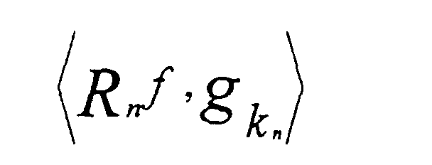 is maximized, and Rmf is a residual component to be
searched for at the m-th searching step. Thus, as the
number of steps n increases, the representation accuracy
of the signal f is enhanced. That means that the larger
the number of bases used to represent the signal f, the
more accurately the signal f can be represented.
Therefore, the larger the number of bases is, that is, the
more times of searching steps there are, the more the code
amount is and the smaller the distortion is.
is maximized, and Rmf is a residual component to be
searched for at the m-th searching step. Thus, as the
number of steps n increases, the representation accuracy
of the signal f is enhanced. That means that the larger
the number of bases used to represent the signal f, the
more accurately the signal f can be represented.
Therefore, the larger the number of bases is, that is, the
more times of searching steps there are, the more the code
amount is and the smaller the distortion is.
An ideal basis search corresponds to a process
for searching for a basis such that for every pixel in a
frame, the above inner product is maximized among all
predetermined bases (waveform patterns) with respect to a
signal waveform whose center is the pixel. For that
search, it is necessary to compute enormous arithmetic
operations (the number of pixels in a frame) × (the number
of bases) of the inner product. In order to decrease the
number of arithmetic operations without the loss of
optimality as much as possible, the above-mentioned
reference proposes a method to detect a domain with high
electric power and search for a basis in an area adjacent
to the domain.
FIG. 5 shows a diagram illustrating a detailed
structure of the basis searching part 13 according to the
embodiment of the present invention.
In FIG. 5, the basis searching part 13 comprises
a search start point determination part 13-1 and a basis
determination part 13-3. The search start point
determination part 13-1 receives the prediction residual
signal 8 as its input and searches for a domain with the
maximal electric power in the prediction residual signal 8.
A position in the searched domain is considered as a start
point of the basis search, and image data (partial signal
waveform) of an area adjacent to the start point (for
example, S pixels × S lines) is supplied to the basis
determination part 13-3 as an inner product arithmetic
target signal (Rnf) 13-2. The basis determination part
13-3 retrieves individual basis code words 13-4 from the
basis code book 14, performs inner product operations of
the inner product arithmetic target signal 13-2 and the
individual basis code words 13-4, and determines a pair of
signal and basis such that the inner product is maximized.
Regarding the prediction residual signal 8, the basis gk
is determined among basis vectors in the basis code book
14. Then, the basis determination part 13-3 outputs as a
code parameter 24 a code number (an index) of the basis gk,
the inner product (basis coefficient) and a pixel position
pk = (xk, yk) where the basis gk is applied. Here, the
pixel position pn corresponds to a position of the center
pixel of Rnf. A triple of the code parameters is referred
to as an atom.
The basis determination part 13-3 supplies a
signal reconstructed from the atom in accordance with the
above formula (1). The reconstructed signal is subtracted
from the prediction residual signal 8, and then the
prediction residual signal is updated for the next
searching step. Hereinafter, the searching step is
incremented until the acceptable code amount is reached.
The atom is determined for each of the searching steps.
In order to reconstruct the signal f by the
image decoder 17, it is necessary to encode and transmit
the atom parameter 24 extracted for each searching step.
Back to FIG. 2, the basis encoding part 15 serves for this
encoding operation (step S5). A basis index of the atom
undergoes a compression encoding operation by means of a
variable-length encoding corresponding to emergence
frequency of the basis index, and a basis coefficient of
the atom undergoes a compression encoding operation by
means of a scalar quantization. (It is noted that the
basis coefficient is quantized in the basis determination
part 13-3 in FIG. 5 because the basis coefficient is
required to represent a signal for each searching step and
gives an influence to the basis searching process.)
Furthermore, it is necessary to encode the position
information pn of the atom. If the atom is supposed to be
located at an arbitrary pixel position in the frame, there
arises a problem in that a code amount required to
represent the position increases.
Thus, in the embodiment of the present invention,
feasable values to the position pn are restricted to
multiplicative values of a 2×2 block. As a result, since
the center of an atom is always located at a vertex of the
2×2 block, it can be determined per 2×2 block whether or
not there is an atom to be encoded. Since the image
encoder 2 and the image decoder 17 according to the
embodiment of the present invention have a bitstream
formed of a macroblock with 16×16 pixels as a unit, the
information regarding whether or not the atom exists can
be described as a four-layer quadrival tree structure
whose root is a macroblock as shown in FIG. 6. FIG. 7
shows an example of a code representation of the quadrival
tree structure.
In FIG. 7, the level of the macroblock (16×16)
represents by 1 bit just whether there is an atom in an
interior of the macroblock (1) or not (0). The level of
block (8×8) represents by at most 4 bits how atoms are
distributed in four 8×8 blocks included in the macroblock.
Similarly, the level of block (4×4) and the level of
block (2×2) have code representations by at most 16 bits
and 64 bits, respectively. Here, if there appears a
vertex having a code "0", not any code has to be assigned
for successors of the vertex. For example, in a case in
which there is no atom in a macroblock, the quadrival tree
may have only one vertex information item. Also,
according to a property of the prediction residual signal,
atoms often tend to concentrate spatially. Thus, when an
optimal variable-length code is designed based upon a
conditional probability and an arithmetic code or the like
is employed, it is possible to shorten an average code
length by assigning a short code length for a tree having
many 1s.
By applying the above-mentioned method, it is
possible to decrease the number of basis searching points
and the arithmetic operations thereof rather than the
method to perform a search operation per pixel. Also, the
above-mentioned method represents a position of the basis
searching point pn as the position in the macroblock by
using a tree structure whose root is the macroblock. As a
result, whatever display size the image information has,
it is possible to fix a maximal code amount required to
identify the position of the basis searching point.
Furthermore, in a domain where atoms do not concentrate,
the tree structure makes it possible to represent the
position pn of a basis searching point by a lesser code
amount and decrease the code amount from a whole frame
required to represent the position pn of each basis
searching point, if general characteristics of an image
are considered.
Whenever atoms are encoded for each of the
above-mentioned search steps, it is determined at step S8
whether or not the code amount reaches the acceptable code
amount. If the code amount reaches the acceptable code
amount, the basis searching process is stopped and the
encoding of the prediction residual signal of the frame of
interest is terminated. Then, if there remain some frames
(step S9), the process for the next frame is performed
back to step S1. If there is no remaining frame, the
process is terminated.
When the encoding process for atoms
corresponding to one frame is completed, a local decoding
process is performed and the frame memory 11 is updated so
as to obtain a reference image for the motion compensation
prediction after the next frame (the basis local decoding
part 16, steps S6 and S7).
In the above-mentioned manner, the bitstream 3
including encoding information generated by the image
encoder 2 is supplied to the image decoder 17 via the line
30.
On the other hand, the image decoder 17 receives
the bitstream 3 including the above encoding information
and performs the same process as the basis local decoding
part 16. In a case in which an image is decoded and
displayed in real time, the decoding process is performed
in accordance with steps that will be mentioned with
respect to FIG. 3.
In FIG. 3, based upon occupied information 20 of
bitstream data saved in the receiving buffer 19, a time
management function of the decoding control part 18
determines a decoding start time of a frame being at the
time t and runs a basis decoding part 21 at the time (step
S10). The basis decoding part 21 detects a frame
synchronous word and analyzes atom data of the bitstream
in accordance with a predetermined syntax rule (step S11).
The prediction signal generating part 7-2 (which performs
a process corresponding to the prediction signal
generating part 7-1 in the image encoder 2) receives
prediction result output information 10 including
information regarding a motion vector and a prediction
mode in the analyzed data, and then generates a prediction
image 9 (step S12). An atom decoding process identifies a
basis with reference to a basis index and a basis code
book 14-2 equivalent to the basis code book 14-1 in the
image encoder 2 and reconstructs a prediction residual
signal f(x, y) based upon the formula (1) (step S13). The
position information (ref. FIG 6 and FIG. 7) regarding a
macroblock where the basis is applied is transformed into
a position in a frame of the prediction residual signal.
The prediction residual signal f(x, y) is
generated by the prediction signal generating part 7-2, is
processed by a filter 23-2 and is added as the prediction
image 9. Then, a final frame decoding image is generated
by using the above position in the frame. The decoded
image is saved in a displaying buffer 22 (step S14) and is
written in the frame memory 11 for the decoding process of
the next frame. The displaying buffer 22 may be provided
to use a portion of a frame memory 11-2.
At the displaying time that is prescribed in the
bitstream or is determined according to a rule prescribed
in the image decoder 2, the decoding control part 18 runs
the displaying buffer 22 and displays the frame image
being at the time t on the screen (steps S15 and S16).
In this embodiment of the present invention,
when an atom, which is formed of code parameters, is
encoded in accordance with the "Matching Pursuits" method,
it is possible to efficiently encode per macroblock the
atom that may be at an arbitrary position in a frame.
That improves the overall coding efficiency.
Regarding FIG. 1, the line 30 may be a network
such as the Internet or a data reading circuit for reading
and decoding a bitstream from a medium in which an output
result of the image encoder 2 is recorded.
A description will now be given of an image
encoder and an image decoder according to a second
embodiment of the present invention. Especially in this
embodiment, a description will be given of an example of
an image encoder and an image decoder to perform a quality
hierarchical encoding and a transmission by using the
"Matching Pursuits". In the image encoder and the image
decoder according to the embodiment, the "Matching
Pursuits" provides a basis representation of an encoding
distortion signal, which is transmitted as additional
information. As a result, when a line in use has a good
condition, it becomes possible to transmit a high quality
picture.
FIG. 8 shows a structure of the image encoder
and the image decoder according to the embodiment of the
present invention.
In FIG. 8, the image encoder comprises an
encoding control part 111, a base-layer encoding part 102,
a base-layer local decoding part 103, a base-layer frame
memory 104-1, an enhance-layer encoding part 106 and a
rate buffer 112. The enhance-layer encoding part 106 for
producing and encoding the basis representation of an
encoding distortion signal comprises a basis code book
108-1, a basis searching part 109 and a basis encoding
part 110.
On the other hand, the image decoder, which is
connected with the image encoder via the line 30,
comprises a decoding control part 114, a receiving buffer
115, a base-layer decoding part 117, a base-layer frame
memory 104-2, an enhance-layer decoding part 118 and a
displaying buffer 122. The enhance-layer decoding part
118 for decoding an encoding distortion signal transmitted
from the image encoder as enhance-layer information
comprises a basis decoding part 119 and a basis code book
108-2.
The image encoder performs a compression
encoding for a picture signal (a source image) per frame.
The image encoder represents a signal underlying a picture
through a base layer encoding and encodes an encoding
distortion signal, which is represented as a difference
between the source image and the encoded image, in the
enhance layer. For each layer, individual frames are
encoded per macroblock formed of 16 pixels × 16 lines of
a luminance signal. After a base-layer bitstream and an
enhance-layer bitstream are generated separately, an
eventual bitstream is formed. In general, the image
decoder is formed so as to perform an inter layer
synthesis (in which a decoded image in the enhance layer,
that is, an encoding distortion component, is added to a
decoded image in the base layer) by using a time stamp of
an individual frame. Since the bitstream in the base
layer and the bitstream in the enhance layer are separated,
it is possible to perform transmission control such that
at a sending process, only the bitstream in the base layer
is sent to the image decoder that can receive only the
base layer.
The image encoder performs an encoding process,
for example, in accordance with a procedure as shown in
FIG. 9.
In FIG. 9, the encoding control part 111 sets
initial code parameters necessary to perform an encoding
together with an acceptable code amount of the frame of
interest (step S1). The code parameters includes an
initial quantization parameter and encoding mode
information indicating whether or not a frame is encoded
exclusively in the frame and whether or not the frame is
encoded by using an inter frame prediction. (It is noted
that in this embodiment of the present invention, the
enhance layer has no inter frame prediction.) The code
parameters are determined separately for the based layer
and the enhance layer based upon an inter layer code
amount allocation rule according to the use of an encoding
and decoding system. As mentioned in the first embodiment
of the present invention, an adjusting factor of the code
amount in the enhance layer is mainly the number of atoms.
After the second frame, the acceptable code
amount of the next frame is set by receiving a feedback of
occupied amount 113 to the encoding control part 111 so
that the rate buffer 112 cannot overflow.
The base-layer encoding part 102 encodes the
picture signal 1 (the source image) in accordance with an
arbitrary picture encoding method such as MPEG-4 video
encoding method (ISO/IEC 14496-2) and ITU-T H.263 (step
S102). Here, the picture signal 1 may be encoded in
accordance with the "Matching Pursuits" method mentioned
in the first embodiment of the present invention. Encoded
data of an individual frame is decoded into a decoded
image 105 by the base-layer local decoding part 103 and is
saved in the frame memory 104-1 so as to perform a motion
compensation prediction after the next frame.
A base-layer encoding distortion signal 107 is
generated by computing a difference between the input
picture signal 1 and the decoded image 105 in the base
layer (step S103). The enhance-layer encoding part 106
encodes the encoding distortion signal 107 based upon the
"Matching Pursuits". A procedure of the "Matching
Pursuits" encoding according to this embodiment (steps
S104 through S109) is identical to the procedure mentioned
in steps S4 through S9 (ref. FIG. 2) according to the
first embodiment. It is noted that the enhance-layer
encoding part 106 has no processing part serving to
execute an inter frame motion compensation prediction
process, because the enhance-layer encoding part 106
performs an intra frame encoding for the encoding
distortion signal 107. The basis searching part 109 and
the basis encoding part 110 perform processes
corresponding to the basis searching part 13 and the basis
encoding part 15 shown in FIG. 1, respectively.
It is noted that although the basis code book
108-1 has the same constitution as the basis code book 14-1
shown in FIG. 1, a basis pattern, that is, a code word,
may be redesigned to adapt a characteristic of the
encoding distortion signal 107. Especially, when
employing a conventional picture encoding method in which
the DCT is used to encode the base layer, there appears a
visually noticeable pattern in the base layer such as a
block distortion peculiar to the DCT. The use of the
basis code book aiming at such a pattern makes it possible
to efficiently encode the enhance layer.
The image decoder receives a bitstream
transmitted from the image encoder and synchronously
performs each decoding process of the base layer and the
enhance layer. When an image is decoded and displayed in
real time, the decoding process, for example, follows the
procedure shown in FIG. 10.
In FIG. 10, based upon occupied amount
information 116 of a bitstream data saved in the receiving
buffer 115, a time management function of the decoding
control part 114 determines a decoding start time of a'
frame being at the time t. When the time comes (step
S110), the time management function of the decoding
control part 114 runs the base-layer decoding part 117 and
the basis decoding part 119 of the enhance-layer decoding
part 118 (steps S111 through S113). While performing a
motion compensation process, the basis-layer decoding part
117 uses the frame memory 104 to generate a decoded image
120 in the base layer (step S112). The basis decoding
part 119 analyzes atom data in the bitstream in accordance
with a predetermined syntax rule (step S113). In an atom
decoding process, a basis is identified by the basis code
book 108-2 similar to that of the image encoder based upon
a basis index, and an encoding distortion decoded image
121 is generated based upon the formula (1) (step S114).
In order to generate a high quality image including the
enhance layer, the base-layer decoded image 120 is added
to the encoding distortion decoded image 121 and the
resulting image is written in the displaying buffer 122
(step S115). There is a case in which the enhance layer
is not properly sent to the image decoder depending on a
line condition. In such a case, only the base-layer
decoded image 120 is written in the displaying buffer 122
and is displayed. The displaying buffer 122 may is
provided to use a portion of the base-layer frame memory
104-2. At the displaying time that is prescribed by the
bitstream or is determined according to a rule prescribed
in the image decoder the decoding control part 114 runs
the displaying buffer 122 and displays the frame being at
the time t on the screen (steps S116 and S117).
In this embodiment of the present invention, the
encoded data by the "Matching Pursuits" is used in the
enhance layer to form a quality hierarchical code. As a
result, it is possible to efficiently represent without
distortion a visually noticeable pattern such as a block
distortion generated by the base-layer encoding by means
of the DCT.
Regarding FIG. 8, a line 123 may be a network
such as the Internet or a data reading circuit for reading
and decoding a bitstream from a medium in which an output
result of the image encoder is recorded.
A description will now be given of an image
encoder and an image decoder according to a third
embodiment of the present invention.
In this embodiment, a description will be given
of another example of an image encoder and an image
decoder to perform a quality hierarchical encoding and a
transmission by using the "Matching Pursuits". In the
image encoder and the image decoder according to the
embodiment, unlike the second embodiment of the present
invention, an encoding distortion signal to be encoded is
divided into a plurality of classes of signal patterns,
and a signal pattern is classified without the use of
additional information with reference to code parameters
in the base layer. A control part is designed to use a
code book aiming at an individual pattern. As a result,
it is possible to perform the "Matching Pursuits" encoding
more efficiently.
FIG. 11 shows a structure of the image encoder
and the image decoder according to the embodiment of the
present invention, wherein those parts in FIG. 11
corresponding to the parts described in FIG. 8 are
designated by the same reference numerals.
In FIG. 11, the image encoder uses an enhance-layer
encoding part 201 whose structure is different from
that of the enhance-layer encoding part 106 shown in FIG.
8. The enhance-layer encoding part 201 comprises a basis
searching part 202, basis code books 203a-1 and 203b-1, a
switch SW 204-1 and a basis encoding part 110. Also, the
image decoder uses an enhance-layer decoding part 207
whose structure is different from that of the enhance-layer
decoding part 118 shown in FIG. 8. The enhance-layer
decoding part 207 comprises a basis decoding part
208, basis code books 203a-2 and 203b-2, and a switch SW
204-2.
An encoding process of the above image encoder
basically follows the process mentioned with respect to
the second embodiment of the present invention. Namely,
after completing the initialization process (ref. S101 in
FIG. 9) and the base-layer encoding process (ref. S102 in
FIG. 9), the encoding process is performed for the
encoding distortion signal, which is to become enhance
information. The enhance-layer encoding process is
performed as follows.
From a difference between an input picture
signal 101 and a decoded image 105 in the base layer, a
base-layer encoding distortion signal 107 is generated.
An enhance-layer encoding part 201 encodes the base-layer
encoding distortion signal 107 based upon the "Matching
Pursuits". The enhance-layer encoding part 201 of the
embodiment has two kinds of basis code books A and B
(referred to as 203a-1 and 203b-1, respectively). It is
supposed that the basis code book A 203a-1 specifically
aims at a block distortion arising when the DCT is
performed for the base layer and the basis code book B
203b-1 aims at an application to a signal pattern other
than the block distortion. When the block distortion
caused by a DCT quantization noticeably arises in a
decoding image in the base layer, the component
corresponding to the distortion also arises in the
encoding distortion signal 107. The coarser the
quantization is, the more noticeably the component arises.
In addition, since a position of the boundary between
blocks is fixed, it can be determined whether or not to
use the code book aiming at the block distortion based
upon a quantization step value in the base layer and a
signal position in which a basis is being searched. For
the implementation, the switch SW 204-1 for switching the
basis code books A/B is used. When receiving a
quantization step value 206 in the base-layer and a signal
position 205 in which a basis is being searched, the
switch SW 204-1 determines which to use the basis code
book A or B in accordance with a predetermined criterion
so as to employ a basis vector thereof.
In this case, since the switch SW 204-2 in the
image decoder uses an existing value as determination
information, it is unnecessary to transmit some additional
information for the determination and it is possible to
efficiently perform the "Matching Pursuits" encoding
process dynamically adaptable to the signal pattern.
The basis searching part 202 operates similarly
to the basis searching part 109 mentioned in the second
embodiment except that the basis searching part 202
supplies the signal position in which a basis is being
searched for to the switch SW204-1.
The above image decoder uses the enhance-layer
decoding part 207 only whose structure is different from
that of the enhance-layer decoding part 118 (ref. FIG. 8)
in the second embodiment. The basis decoding part 208
operates similarly to the basis decoding part 119
mentioned in the second embodiment except that the basis
decoding part 208 outputs atom position information 205 to
the switch SW 204-2. Also, the switch SW 204-2 receives
the quantization step value 206 at the corresponding
position in the base layer from the base-layer decoding
part 117. With reference to the atom position information
205 and the quantization step value 206, the switch SW
204-2 determines which basis code book A or B should be
used in accordance with the same criterion as the enhance-layer
encoding part 201.
In the above system structure, it is possible
to classify an encoding distortion signal to be encoded by
the "Matching Pursuits" into either a class of visually
noticeable signal patterns such as a block distortion
caused by encoding the base-layer with the use of the DCT
or a class of other signal patterns with respect to the
quality hierarchical encoding using the "Matching
Pursuits" encoding. In addition, it is possible to use
selectively the basis code book suitably for each class.
At the same time, since the basis code book is segmented
before the search, it is possible to decrease the number
of arithmetic operations for searching an atom and shorten
the code length of the basis index. When the base-layer
encoding parameter is used to choose the basis code book,
particular information is not required. More than or
equal to two basis code books may be prepared. One basis
code book may be divided into some classes.
In the embodiment, the description has been
given of another example of the image encoder and the
image decoder to perform a quality hierarchical encoding
and a transmission by using the "Matching Pursuits".
Unlike the structure of the second embodiment mentioned
above, the embodiment introduces a motion compensation
prediction so as to remove the redundancy in the time
direction of the encoding distortion signal to be encoded.
The use of the motion compensation prediction makes it
possible to more efficiently encode the enhance layer.
A description will now be given of an image
encoder and an image decoder according to a fourth
embodiment of the present invention. In this embodiment,
a description will be given of another example of the
image encoder and the image decoder to perform a quality
hierarchical encoding and a transmission by using the
"Matching Pursuits". Unlike the structure of the second
embodiment mentioned above, the embodiment introduces
motion compensation prediction so as to remove the
redundancy in the time direction of the encoding
distortion signal to be encoded. The use of the motion
compensation prediction makes it possible to more
efficiently encode the enhance layer.
FIG. 12 shows a structure of the image encoder
and the image decoder according to the fourth embodiment
of the present invention, wherein those parts in FIG. 12
corresponding to the parts described in FIG. 8 are
designated by the same reference numerals.
In FIG. 12, the image encoder uses an enhance-layer
encoding part 301 whose structure is different from
that of the enhance-layer encoding part 106 shown in FIG.
8. The enhance-layer encoding part 301 comprises a basis
searching part 109, a basis encoding part 110, a basis
local decoding part 302, a motion detection and prediction
signal generating part 303, an enhance-layer frame memory
304-1 and a basis code book 308-1. Also, the image
decoder uses an enhance-layer decoding part 309 whose
structure is different from that of the enhance-layer
decoding part 118 shown in FIG. 8. The enhance-layer
decoding part 309 comprises an enhance-layer frame memory
304-2, a basis code book 308-2, a basis decoding part 310
and a prediction signal generating part 311.
An encoding process of the above image encoder
basically follows the process mentioned with respect to
the second embodiment of the present invention. Namely,
after completing the initialization process (ref. S101 in
FIG. 9) and a base-layer encoding process (ref. S102 in
FIG. 9), the encoding process is performed for the
encoding distortion signal which is to become enhance
information. The enhance-layer encoding process is
performed as follows.
In the enhance-layer encoding part 301, an inter
frame motion compensation prediction is performed for the
encoding distortion signal 107, and the prediction
residual signal 307 is encoded. The encoding distortion
signal 107 depends upon an image pattern in the base layer.
Since correlation between frames with respect to the
encoding distortion signal can be also considered to be
high, the execution of the motion compensation prediction
makes it possible to decrease the redundancy in the time
direction and perform an efficient encoding.
The enhance-layer encoding part 301 encodes the
encoding distortion signal 107 based upon the "Matching
Pursuits" with the motion compensation. FIG. 13 shows a
procedure of the motion compensation prediction.
When the encoding distortion signal 107 is
delivered to the motion detection and prediction signal
generating part 303, a prediction signal 305 is generated.
The prediction signal 305 is determined per macroblock.
The macroblock counter n is reset (step S301). Then, the
intra frame prediction is performed for the macroblock n
(step S302). A variety of intra frame prediction methods
is assumed. For example, a pixel average of an input
macroblock (DC component) may be used as a prediction
image. Also, values of marginal pixels of the macroblock
that have already been encoded may be buffered, and the
values may be used to generate a prediction image through
a plane prediction.
In step S302, a prediction cost incurred by the
prediction image data (P_intra) and the inter frame
prediction is computed. When a plurality of prediction
methods are used, intra frame prediction mode information
is also produced to indicate what type of intra frame
prediction method has been used. Regarding the prediction
cost, a sum of absolute difference (SAD) and a mean square
error (MSE) may be used to represent a residual power.
Besides, a code amount-distortion cost representation
including additional information required for a prediction
method (such as above-mentioned intra frame prediction
mode information) may be used.
Then, the inter frame prediction is performed
through a motion compensation prediction (step S303). The
inter frame prediction predicts a motion between frames
and identifies a similar image in reference images in the
enhance-layer frame memory 304-1. In motion detection, a
motion vector is detected as information to identify the
similar image in the reference images. The motion vector
may be represented in any form such as a parallel shift
vector by block matching often used in existing picture
encoding methods, a vector representing an affine model,
or a vector representing a perspective transform model.
In general, the more complicated a model is and the larger
the number of motions that can be represented, the smaller
the prediction residual is. On the other hand, since
arithmetic operations for the motion detection and the
number of parameters for the model representation increase
corresponding to the above benefit, it is necessary to
make a selection from the viewpoint of a balance between
implementation burden and performance. Regarding motion
vector search and representation method, any
representation is available in this embodiment of the
present invention as long as it can be represented as
motion information representation having a macroblock as a
unit. Also, like an 8×8 pixel unit prediction mode of
MPEG-4, a macroblock may be further divided into smaller
blocks and a motion vector is found for each divided block.
Like a B frame prediction of MPEG-1/2, a plurality of
frames may be referred to in order to perform a prediction.
In a case in which a plurality of prediction methods are
switched, inter frame prediction mode information is
produced to indicate what type of prediction method has
been used. The inter frame prediction mode may be such a
mode that "Matching Pursuits" encoding data of an encoded
frame is saved (for the storage, it is required to prepare
a memory space to save an atom parameter 24 corresponding
to the frame memory 11) and atom information encoded in a
reference frame is inherited without change. At step S303,
prediction image data (P_inter), a motion vector, inter
frame prediction mode information, and a prediction cost
incurred by a motion compensation prediction are computed.
Regarding the prediction cost, the SAD, the MSE and the
code amount-distortion cost may be used like the intra
frame prediction. As a code amount which should be
considered in the inter frame prediction, there are a code
amount of a motion vector itself, switch information of a
motion vector model, inter frame prediction mode
information and so on.
At step S304, it is determined which type of
prediction is performed for the macroblock of interest,
the intra frame prediction (INTRA) or the inter frame
prediction (INTER). The two above-mentioned prediction
costs are used as an evaluation value with respect to the
predictions and the prediction incurring the smaller
prediction cost is chosen. If the intra frame prediction
(INTRA) is chosen, a prediction image Pred(n) for the
macroblock n is set to a P_intra and the intra frame
prediction mode information is output as output
information 306. If the inter frame prediction (INTER) is
chosen, a prediction image Pred(n) is set to a P_inter and
the inter frame prediction mode information together with
a motion vector are output as the output information 306
(steps S305 and S306). After that, the macroblock counter
n is incremented (S307). If the above-mentioned process
is completed for every macroblock in the frame (step S308),
the prediction image generating process is completed.
A difference between the generated prediction
image 305 and the encoding distortion signal 107 is
computed. Then, the computed residual signal 307 is
supplied to the basis searching part 109. Since the
operations of the basis searching part 109 and the basis
encoding part 110 are the same as that of the first
embodiment of the present invention, the description
thereof will be omitted. The basis code book 308-1 is
designed to reflect the prediction residual pattern of the
encoding distortion signal in the time direction.
Although not shown in the diagram, a plurality
of prepared basis code books may be switched according to
the quantization step value in the base layer or atom
position information similarly to the third embodiment.
Especially regarding the atom position information, a
discontinuous portion between macroblocks may arise in a
prediction image because the motion detection by the
enhance-layer encoding part 301 has a macroblock as a unit.
Thus, it is possible to efficiently perform the "Matching
Pursuits" if the code book suitable for the discontinuous
signal pattern is prepared.
Motion vector and prediction mode information
306 together with an atom parameter 313 are multiplexed to
a bitstream and are transmitted to the image decoder. The
encoded atom parameter 313 is sent to the basis local
decoding part 302 and a decoded image of the prediction
residual signal 307 is generated. The decoded image is
saved in the enhance-layer frame memory 304-1 for encoding
the next frame.
In the above image decoder, only the structure
of the enhance-layer decoding part 309 is different from
that of the enhance-layer decoding part 118 in the second
embodiment (ref. FIG. 8). In the enhance-layer decoding
part 309, the basis decoding part 310 performs the same
operations as the basis local decoding part 302 with
reference to the basis code book 308-2. The prediction
signal generating part 311 generates a prediction image
305 according to the motion vector and prediction mode
information 306. The decoding control part 114 controls
operations of each decoding part so that frames of the
base layer and the enhance layer can be decoded
synchronously. Other operations such as the displaying
control follow the operation mentioned in the second
embodiment.
According to the structure of the embodiment, in
a quality hierarchical encoding using the "Matching
Pursuits", if the motion compensation prediction is
introduced for the encoding distortion signal to be
encoded on the "Matching Pursuits", it is possible to more
efficiently encode the enhance layer. The above-mentioned
enhance-layer encoding part 301 and the enhance-layer
decoding part 309 may be substituted for an enhance-layer
encoding part 410 and an enhance-layer decoding part 405,
respectively.
In this case, in the enhance-layer encoding part
motion vector information obtained as an encoding result
of the base layer is used as a motion vector of the
macroblock which is located at the same position as the
enhance layer. In order to simplify a process of a motion
detection and prediction signal generating part 403 and
decrease additional information to be transmitted, the
enhance-layer encoding part 401 uses the motion vector of
the macroblock located at the same position as the enhance
layer which has been detected in the base layer to
generate an inter frame prediction signal. In general,
since a correlation of the image pattern between the base
layer and the enhance layer is high in the quality
hierarchical encoding, motion information detected in the
base layer is often directly used in the enhance layer
efficiently. Also, in order to increase the coding
efficiency in the enhance layer, motion detection may use
the base-layer motion information 402 as an initial value
to be performed for an infinitesimal domain around the
base-layer motion information 402. Since initial value
regarding a motion searching point is given, it is
sufficient to search a motion only in the neighborhood of
the initial value and it is possible to reduce the number
of arithmetic operations. In this case, a detection
result in the enhance layer is sent to the image decoder
as additional information, which is set as difference
information 404 based upon the base-layer motion
information 402. If the base-layer motion information 402
is directly used as the motion difference information 404,
it is unnecessary to transmit the motion difference
information 404.
In such a case in which the base-layer motion
vector information is used to perform the enhance-layer
motion compensation prediction in the enhance-layer
encoding part 401, the enhance-layer decoding part 405
receives the base-layer motion information 402 from the
base-layer decoding part 117 and uses the motion
difference information 404 included in a bitstream in the
enhance layer to generate the prediction image 305 in a
prediction signal generating part 406.
As mentioned above, according to the claims 1
through 62, it is possible to realize the image encoding
method and the image encoder and the corresponding image
decoding method and the corresponding image decoder
capable of improving the total coding efficiency by
representing encoded data more compactly by means of the
pattern matching technique. Also, according to the claims
63 and 64, it is possible to realize the image processing
system that performs an image encoding and decoding in
accordance with such a method mentioned in the previous
claims.
Claims (64)
- An image encoding method, comprising:wherein the image signal is encoded from a combination of the information to identify the waveform vector, the similarity information and the position in the image of the partial signal waveform, and wherein the position in the image of the partial signal waveform is encoded through replacement with position information in a predetermined partial domain of the image signal.a pattern matching step searching for a waveform vector similar to a partial signal waveform of an image signal in a predetermined group of waveform vectors; anda waveform pattern encoding step performing a compression encoding for information to identify the waveform vector searched for, similarity information to represent similarity between the partial signal waveform and the waveform vector searched for, and a position in an image of the partial signal waveform in accordance with a predetermined encoding rule,
- An image encoding method, comprising:wherein in a process in which the pattern matching step and the waveform pattern encoding step are iterated until a predetermined condition is satisfied, whenever encoding information is obtained at the waveform pattern encoding step, a reconstructed waveform of a partial signal waveform obtained from the encoding information is subtracted from the image signal so as to produce an image signal to be provided to the pattern matching step, and the image signal is encoded according to the encoding information obtained at the waveform pattern step until the predetermined condition is satisfied, and wherein the position in the image of the partial signal waveform is encoded through replacement with position information in a predetermined partial domain of the image signal.a pattern matching step searching for a waveform vector in a predetermined group of waveform vectors based upon inner products of the waveform vectors and a partial signal waveform of an image signal; anda waveform pattern encoding step performing a compression encoding for information to identify the waveform vector searched for, an inner product value of the partial signal waveform and the waveform vector searched for, and a position in an image of the partial signal waveform in accordance with a predetermined encoding rule,
- The image encoding method as claimed in claim 2, wherein in the pattern matching step, pixels formed of a predetermined power of 2×2 of an image signal represented by a predetermined pixel unit are set as a unit, and a position in an image of a partial signal waveform to be encoded is identified.
- The image encoding method as claimed in claim 2, wherein the predetermined partial domain is divided into unit blocks to identify a position and is stratified in a block domain formed of one unit block or a plurality of unit blocks based upon an inclusive relation, and the position in the image of the partial signal waveform is encoded based upon a sequence of bits indicating whether or not each block domain of an individual layer includes a position of a partial signal waveform to obtain an inner product value of the partial signal waveform and a waveform pattern in a group of waveform patterns.
- The image encoding method as claimed in claim 2, wherein the image signal to be processed is information representing a source image to be encoded.
- The image encoding method as claimed in claim 2, wherein the image signal to be processed is information representing a prediction residual image obtained by performing a motion compensation prediction for a source image to be processed.
- The image encoding method as claimed in claim 2, wherein the image signal to be processed is an encoding distortion signal generated by encoding a source image in accordance with a predetermined encoding rule.
- The image encoding method as claimed in claim 2, wherein the image signal to be processed is information representing a prediction residual image obtained by performing a motion compensation prediction for an encoding distortion signal generated by encoding a source image in accordance with a predetermined encoding rule.
- The image encoding method as claimed in claim 8, wherein when the information representing the prediction residual image is obtained, motion information detected by encoding the source image is used to perform the motion compensation prediction.
- The image encoding method as claimed in claim 9, wherein the motion information detected by encoding the source image is set as an initial value, motion information is detected in positions adjacent to a position where a motion regarding the initial value occurs, and the motion information is used to perform the motion compensation prediction.
- An image encoder, comprising:wherein the image signal is encoded from a combination of the information to identify the waveform vector, the similarity information and the position in the image of the partial signal waveform, and wherein the waveform pattern encoding part encodes the position in the image of the partial signal waveform through replacement with information regarding position in a predetermined partial domain of the image signal.a pattern matching part searching for a waveform vector similar to a partial signal waveform of an image signal in a predetermined group of waveform vectors; anda waveform pattern encoding part performing a compression encoding for information to identify the waveform vector searched for, similarity information to represent similarity between the partial signal waveform and the waveform vector searched for, and a position in an image of the partial signal waveform in accordance with a predetermined encoding rule,
- An image encoder, comprising:wherein in a process in which operations on the pattern matching part and the waveform pattern encoding part are iterated until a predetermined condition is satisfied, whenever encoding information is obtained at the waveform pattern encoding part, a reconstructed waveform of a partial signal waveform obtained from the encoding information is subtracted from the image signal so as to produce an image signal to be provided to the pattern matching part, and the image signal is encoded according to the encoding information obtained by the waveform pattern part until the predetermined condition is satisfied, and wherein the position in the image of the partial signal waveform is encoded through replacement with position information in a predetermined partial domain of the image signal.a pattern matching part searching for a waveform vector in a predetermined group of waveform vectors based upon inner products of the waveform vectors and a partial signal waveform of an image signal; anda waveform pattern encoding part performing a compression encoding for information to identify the waveform vector searched for, an inner product value of the partial signal waveform and the waveform vector searched for, and a position in an image of the partial signal waveform in accordance with a predetermined encoding rule,
- The image encoder as claimed in claim 12, wherein the pattern matching part sets pixels formed of a predetermined power of 2×2 of an image signal represented by a predetermined pixel unit as a unit and identifies a position in an image of a partial signal waveform to be encoded.
- The image encoder as claimed in claim 13, wherein the predetermined partial domain is divided into unit blocks to identify a position and is stratified in a block domain formed of one unit block or a plurality of unit blocks based upon an inclusive relation, and the waveform pattern encoding part encodes the position in the image of the partial signal waveform based upon a sequence of bits indicating whether or not each block domain of an individual layer includes a position of a partial signal waveform to obtain an inner product value of the partial signal waveform and a waveform pattern in a group of waveform patterns.
- An image encoding method, comprising:wherein a signal corresponding to an error signal between a first image signal provided to the first encoding step and a signal obtained by performing a local decoding process for encoding information obtained at the first image encoding step is set as a second image signal provided to the second image encoding step, and wherein the second image encoding step comprises: a pattern matching step searching for a waveform vector similar to a partial signal waveform of the second image signal in a predetermined group of waveform vectors; and a waveform pattern encoding step performing a compression encoding for information to identify the waveform vector searched for, similarity information to represent similarity between the partial signal waveform and the waveform vector searched for, and a position in the second image of the partial signal waveform in accordance with the second encoding rule, and wherein in the pattern matching step, a group of waveform vectors to be used is selected among a plurality of groups of waveform vectors based on a parameter used to perform the compression encoding at the first image encoding step and the position in the second image of the partial waveform signal.a first image encoding step performing a compression encoding for a first image signal per predetermined partial domain in accordance with a.first encoding rule; anda second image encoding step performing a compression encoding for a second image signal per partial signal waveform of the second image signal in accordance with a second encoding rule,
- An image encoding method, comprising:wherein a signal corresponding to an error signal between a first image signal provided to the first encoding step and a signal obtained by performing a local decoding process for encoding information obtained at the first image encoding step is set as a second image signal provided to the second image encoding step, and wherein the second image encoding step comprises a pattern matching step searching for a waveform vector in a predetermined group of waveform vectors based upon inner products of the waveform vectors and a partial signal waveform of the second image signal; and a waveform pattern encoding step performing a compression encoding for information to identify the waveform vector searched for, an inner product value of the partial signal waveform and the waveform vector searched for, and a position in the second image of the partial signal waveform in accordance with the second encoding rule, wherein in a process in which the pattern matching step and the waveform pattern encoding step are iterated until a predetermined condition is satisfied, whenever encoding information is obtained at the waveform pattern encoding step, a reconstructed waveform of a partial signal waveform obtained from the encoding information is subtracted from the second image signal so as to produce a second image signal to be provided to the pattern matching step, and the second image signal is encoded according to the encoding information obtained at the waveform'pattern step until the predetermined condition is satisfied, and wherein the position in the image of the partial signal waveform is encoded through replacement with position information in a predetermined partial domain of the image signal and in the pattern matching step, a group of waveform vectors to be used is selected among a plurality of groups of waveform vectors based on a parameter used to perform the compression encoding at the first image encoding step and the position in the second image of the partial waveform signal.a first image encoding step performing a compression encoding for a first image signal per predetermined partial domain in accordance with a first encoding rule; anda second image encoding step performing a compression encoding for a second image signal per partial signal waveform of the second image signal in accordance with a second encoding rule,
- The image encoding method as claimed in claim 16, wherein the first image signal to be provided to the first image encoding step becomes information representing a source image to be encoded, and the second image signal to be provided to the second image encoding step becomes an encoding distortion signal generated by encoding the source image at the first image encoding step.
- The image encoding method as claimed in claim 17, wherein the second image signal becomes information representing a prediction residual image obtained by performing a motion compensation prediction for the error signal.
- The image encoding method as claimed in claim 18, wherein at the second image encoding step, when the information representing the prediction residual image is obtained, motion information detected in an encoding process for a source image at the first image encoding step is used to perform the motion compensation prediction.
- The image encoding method as claimed in claim 18, wherein at the second image encoding step, the motion information detected in an encoding process for a source image at the first image encoding step is set as an initial value, motion information is detected in positions adjacent to a position where a motion regarding the initial value has occurred, and the motion information is used to perform the motion compensation prediction.
- The image encoding method as claimed in claim 15, wherein the position in the second image of the partial signal waveform is encoded through replacement with position information in a predetermined partial domain of the second image signal.
- The image encoding method as claimed in claim 21, wherein the predetermined partial domain is divided into unit blocks to identify a position and is stratified in a block domain formed of one unit block or a plurality of unit blocks based upon an inclusive relation, and the position of the partial signal waveform in the second image is encoded based upon a sequence of bits indicating whether or not each block domain of an individual layer includes a position of a partial signal waveform to obtain an inner product value of the partial signal waveform and a waveform pattern in a group of waveform patterns.
- An image encoder, comprising:wherein a signal corresponding to an error signal between a first image signal provided to the first encoding part and a signal obtained by performing a local decoding process for encoding information obtained by the first image encoding part is set as a second image signal provided to the second image encoding part, and wherein the second image encoding part comprises: a pattern matching part searching for a waveform vector similar to a partial signal waveform of the second image signal in a predetermined group of waveform vectors; and a waveform pattern encoding part performing a compression encoding for information to identify the waveform vector searched for, similarity information to represent similarity between the partial signal waveform and the waveform vector searched for, and a position in the second image of the partial signal waveform in accordance with the second encoding rule, and wherein a second image signal is encoded based upon a combination of the information to identify the waveform vector, the similarity information and the position in the second image of the partial signal waveform, and wherein the pattern matching part comprises a plurality of groups of waveform vectors; and a waveform vector group selection part selecting a group of waveform vectors to be used among the groups of waveform vectors based upon a parameter used by the first image encoding part to perform the compression encoding and the position in the second image of the partial waveform signal.a first image encoding part performing a compression encoding for a first image signal per predetermined partial domain in accordance with a first encoding rule; anda second image encoding part performing a compression encoding for a second image signal per partial signal waveform of the second image signal in accordance with a second encoding rule,
- An image encoder, comprising:wherein a signal corresponding to an error signal between a first image signal provided to the first encoding part and a signal obtained by performing a local decoding process for encoding information obtained by the first image encoding part is set as a second image signal provided to the second image encoding part, and wherein the second image encoding part comprises a pattern matching part searching for a waveform vector in a predetermined group of waveform vectors based upon inner products of the waveform vectors and a partial signal waveform of the second image signal; and a waveform pattern encoding part performing a compression encoding for information to identify the waveform vector searched for, an inner product value of the partial signal waveform and the waveform vector searched for, and a position in the second image of the partial signal waveform in accordance with the second encoding rule, wherein in a process in which operations on the pattern matching part and the waveform pattern encoding part are iterated until a predetermined condition is satisfied, whenever encoding information is obtained by the waveform pattern encoding part, a reconstructed waveform of a partial signal waveform obtained from the encoding information is subtracted from the second image signal so as to produce a second image signal to be provided to the pattern matching part, and the second image signal is encoded according to the encoding information obtained by the waveform pattern part until the predetermined condition is satisfied, and wherein the pattern matching part comprises a plurality of groups of waveform vectors; and a waveform vector group selection part selecting a group of waveform vectors to be used among the groups of waveform vectors based upon a parameter used by the first image encoding part to perform the compression encoding and the position in the second image of the partial waveform signal.a first image encoding part performing a compression encoding for a first image signal per predetermined partial domain in accordance with a first encoding rule; anda second image encoding part performing a compression encoding for a second image signal per partial signal waveform of the second image signal in accordance with a second encoding rule,
- The image encoder as claimed in claim 24, wherein the first image signal to be provided to the first image encoding part becomes information representing a source image to be encoded, and the second image signal to be provided to the second image encoding part becomes an encoding distortion signal generated by encoding the source image at the first image encoding part.
- The image encoder as claimed in claim 25, wherein the second image signal becomes information representing a prediction residual image obtained by performing a motion compensation prediction for the error signal.
- The image encoder as claimed in claim 26, wherein when the information representing prediction residual image is obtained, the second image encoding part uses motion information detected in an encoding process for a source image at the first image encoding part to perform the motion compensation prediction.
- The image encoder as claimed in claim 27, wherein the second image encoding part sets the motion information detected in an encoding process for a source image at the first image encoding part as an initial value, detects motion information in positions adjacent to a position where a motion regarding the initial value has occurred, and uses the motion information to perform the motion compensation prediction.
- An image decoding method for receiving compressed image information and reconstructing image information by decompressing the compressed image information per predetermined partial domain, the image decoding method comprising the steps of:decoding compressed image information regarding a predetermined partial domain in accordance with a predetermined decoding rule and obtaining information to identify a waveform vector, similarity information to represent similarity between a partial signal waveform and the waveform vector, and a position in an image of the partial signal waveform;reconstructing image information based upon the waveform vector identified from a predetermined group of waveform vectors by the information to identify a waveform vector, the similarity information, and the position in the image of the partial signal waveform; anddecoding the position in the image of the partial signal waveform included in the compressed image information as information per predetermined partial image domain when the compressed image information is decoded.
- An image decoding method for receiving compressed image information and reconstructing image information by decompressing the compressed image information per predetermined partial domain, the image decoding method comprising the steps of:decoding compressed image information regarding a predetermined partial domain in accordance with a predetermined decoding rule and obtaining information to identify a waveform vector, an inner product value of the waveform vector and a partial signal waveform, and a position in an image of the partial signal waveform;reconstructing image information based upon the waveform vector identified from a predetermined group of waveform vectors by the information to identify a waveform vector, the inner product value, and the position in the image of the partial signal waveform; anddecoding the position in the image of the partial signal waveform included in the compressed image information as information per predetermined partial image domain when the compressed image information is decoded.
- The image decoding method as claimed in claim 30, wherein the predetermined partial domain is divided into unit blocks to identify a position and is stratified in a block domain formed of one unit block or a plurality of unit blocks based upon an inclusive relation, and position information that is encoded based upon a sequence of bits indicating whether or not each block domain of an individual layer includes a position of a partial signal waveform to obtain an inner product value of the partial signal waveform and any waveform pattern of a group of waveform patterns is decoded at the position in the image of the partial signal waveform.
- The image decoding method as claimed in claim 30, wherein encoded information of a source image is decoded as compressed image information.
- The image decoding method as claimed in claim 30, wherein encoded information of a prediction residual image obtained by performing a motion compensation prediction for a source image is decoded as compressed image information.
- The image decoding method as claimed in claim 30, wherein encoded information of an encoding distortion signal generated by encoding a source image in accordance with a predetermined encoding rule is decoded as compressed image information.
- The image decoding method as claimed in claim 30, wherein encoded information of a prediction residual image obtained by performing a motion compensation prediction for an encoding distortion signal generated by encoding a source image in accordance with a predetermined encoding rule is decoded as compressed image information.
- The image decoding method as claimed in claim 33, wherein when a prediction image to be added to a reconstructed prediction residual image is obtained, motion information detected in a decoding process of encoded information of a source image is used to perform a motion compensation.
- The image decoding method as claimed in claim 36, wherein motion information detected in a decoding process of encoded information of a source image is set as an initial value and information representing motions at positions adjacent to a position where a motion regarding the motion information occurs is decoded to perform a motion compensation.
- An image decoder for receiving compressed image information and reconstructing image information by decompressing the compressed image information per predetermined partial domain, comprising:wherein the first part decodes the position in the image of the partial signal waveform included in the compressed image information as information per predetermined partial image domain when the compressed image information is decoded.a first part decoding compressed image information regarding a predetermined partial domain in accordance with a predetermined decoding rule and obtaining information to identify a waveform vector, similarity information to represent similarity between a partial signal waveform and the waveform vector, and a position in an image of the partial signal waveform; anda second part reconstructing image information based upon the waveform vector identified from a predetermined group of waveform vectors by the information to identify a waveform vector, the similarity information, and the position in the image of the partial signal waveform,
- An image decoder for receiving compressed image information and reconstructing image information by decompressing the compressed image information per predetermined partial domain, comprising:wherein the first part decodes the position in the image of the partial signal waveform included in the compressed image information as information per predetermined partial image domain when the compressed image information is decoded.a first part decoding compressed image information regarding a predetermined partial domain in accordance with a predetermined decoding rule and obtaining information to identify a waveform vector, an inner product value of the waveform vector and a partial signal waveform, and a position in an image of the partial signal waveform; anda second part reconstructing image information based upon the waveform vector identified by the information to identify the waveform vector from a predetermined group of waveform vectors, the inner product value, and the position in the image of the partial signal waveform,
- The image decoder as claimed in claim 39, wherein the predetermined partial domain is divided into unit blocks to identify a position and is stratified in a block domain formed of one unit block or a plurality of unit blocks based upon an inclusive relation, and the first part decodes position information that is encoded based upon a sequence of bits indicating whether or not each block domain of an individual layer includes a position of a partial signal waveform to obtain an inner product value of the partial signal waveform and any waveform pattern of a group of waveform patterns at the position in the image of the partial signal waveform.
- The image decoder as claimed in claim 39, wherein the first part decodes encoded information of a source image as compressed image information.
- The image decoder as claimed in claim 39, wherein the first part decodes encoded information of a prediction residual image obtained by performing a motion compensation prediction for a source image as compressed image information.
- The image decoder as claimed in claim 39, wherein the first part decodes encoding information of an encoding distortion signal generated by encoding a source image in accordance with a predetermined encoding rule as compressed image information.
- The image decoder as claimed in claim 39, wherein the first part decodes encoding information of a prediction residual image obtained by performing a motion compensation prediction for an encoding distortion signal generated by encoding a source image in accordance with a predetermined encoding rule as compressed image information.
- The image decoder as claimed in claim 42, wherein the second part contains a motion prediction part performing a motion compensation by using motion information detected in a decoding process of encoded information of a source image when a prediction image to be added to a reconstructed prediction residual image is obtained.
- The image decoder as claimed in claim 45, wherein the motion prediction part uses motion information detected in a decoding process of encoded information of a source image as an initial value and performs a motion compensation by decoding information representing motions at positions adjacent to a position where a motion regarding the motion information occurs.
- An image decoding method, comprising:wherein in the second image decoding step, by decoding the second compressed image information in accordance with a predetermined decoding rule, information to identify a waveform vector, similarity information to represent similarity between a partial signal waveform and the waveform vector, and a position in an image of the partial signal waveform are obtained, and a group of waveform vectors to be used is selected among a plurality of predetermined groups of waveform vectors based upon a code parameter included in the first compressed image information provided to the first image decoding step and the position in the image of the partial waveform signal, and wherein the second image information is generated based upon the waveform vector identified by the information to identify the waveform vector in the selected group of waveform vectors, the similarity information and the position in the image of the partial signal waveform.a first image decoding step receiving first compressed image information and reconstructing a first image by decompressing first compressed image information per predetermined partial domain;a second image decoding step receiving a second compressed image and reconstructing second image information by decompressing the second compressed image information per predetermined partial signal waveform; andan image synthesizing step obtaining output image information by synthesizing the first image information and the second image information,
- An image decoding method, comprising:wherein in the second image decoding step, by decoding the second compressed image information in accordance with a predetermined decoding rule, information to identify a waveform vector, an inner product value of the waveform vector and a partial signal waveform, and a position in an image of the partial signal waveform are obtained, and a group of waveform vectors to be used is selected among a plurality of predetermined groups of waveform vectors based upon a code parameter included in the first compressed image information provided to the first image decoding step and the position in the image of the partial waveform signal, and wherein the second image information is generated based upon the waveform vector identified by the information to identify the waveform vector in the selected group of waveform vectors, the inner product value and the position in the image of the partial signal waveform.a first image decoding step receiving a first compressed image and reconstructing first image information by decompressing the first compressed image information per predetermined partial domain;a second image decoding step receiving a second compressed image and reconstructing second image information by decompressing the second compressed image information per predetermined partial signal waveform; andan image synthesizing step obtaining output image information by synthesizing the first image information and the second image information,
- The image decoding method as claimed in claim 48, wherein when the second compressed image information is decoded at the second image decoding step, the position in the image of the partial signal waveform included in the second compressed image information is decoded as information per predetermined partial image domain.
- The image decoding method as claimed in claim 49, wherein the predetermined partial domain is divided into unit blocks to identify a position and is stratified in a block domain formed of one unit block or a plurality of unit blocks based upon an inclusive relation, and position information that is encoded based upon a sequence of bits indicating whether or not each block domain of an individual layer includes a position of a partial signal waveform to obtain an inner product value of the partial signal waveform and any waveform pattern in a group of waveform patterns is decoded at the position in the image of the partial signal waveform.
- The image decoding method as claimed in claim 47, wherein the first compressed image information provided to the first image decoding step is set as encoded information of a source image and the second compressed image information provided to the second image decoding step is set as encoded information of an encoding distortion signal generated by encoding the source image, and wherein an output image is obtained at the image synthesizing step by synthesizing the first image information regarding the source image obtained at the first image decoding step and the second image information regarding the encoding distortion signal obtained at the second image step.
- The image decoding method as claimed in claim 51, wherein the second compressed image information provided to the second image decoding step is set as encoded information of a prediction residual image obtained by performing a motion prediction compensation for the encoding distortion signal generated'by encoding the source image.
- The image decoding method as claimed in claim 52, wherein at the second image decoding step, when a prediction image to be added to a reconstructed prediction residual image is obtained, motion information detected in a decoding process of encoded information of a source image at the first image decoding step is used to perform a motion compensation.
- The image decoding method as claimed in claim 53, wherein the motion information detected in the decoding process of encoded information of a source image at the first image decoding step is used as an initial value and information representing motions at positions adjacent to a position where a motion regarding the motion information occurs is decoded to perform a motion compensation.
- An image decoder, comprising:wherein the second image decoding part comprises a plurality of predetermined groups of waveform vectors; a first part decoding the second compressed image information in accordance with a predetermined decoding rule and obtaining information to identify a waveform vector, similarity information to represent similarity between a partial signal waveform and the waveform vector, and a position in an image of the partial signal waveform; a second part selecting a group of waveform vectors to be used among a plurality of predetermined groups of waveform vectors based upon a code parameter included in the first compressed image information provided to the first image decoding part and the position in the image of the partial waveform signal; and a third part generating the second image information based upon the waveform vector identified by the information to identify the waveform vector from the selected group of waveform vectors, the similarity information and the position in the image of the partial signal waveform.a first image decoding part receiving a first compressed image and reconstructing first image information by decompressing the first compressed image information per predetermined partial domain;a second image decoding part receiving a second compressed image and reconstructing second image information by decompressing the second compressed image information per predetermined partial signal waveform; andan image synthesizing part obtaining output image information by synthesizing the first image information and the second image information,
- An image decoder, comprising:wherein the second image decoding part comprises a plurality of predetermined groups of waveform vectors; a first part decoding the second compressed image information in accordance with a predetermined decoding rule and obtaining information to identify a waveform vector, an inner product value of a partial signal waveform and the waveform vector, and a position in an image of the partial signal waveform; a second part selecting a group of waveform vectors to be used among a plurality of predetermined groups of waveform vectors based upon a code parameter included in the first compressed image information provided to the first image decoding part and the position in the image of the partial waveform signal; and a third part generating the second image information based upon the waveform vector identified by the information to identify the waveform vector from the selected group of waveform vectors, the inner product value, and the position in the image of the partial signal waveform.a first image decoding part receiving a first compressed image and reconstructing first image information by decompressing the first compressed image information per predetermined partial domain;a second image decoding part receiving a second compressed image and reconstructing second image information by decompressing the second compressed image information per predetermined partial signal waveform; andan image synthesizing part obtaining output image information by synthesizing the first image information and the second image information,
- The image decoder as claimed in claim 56, wherein when the second image decoding part decodes the second compressed image information, the second image decoding part decodes the position in the image of the partial signal waveform included in the second compressed image information as information per predetermined partial image domain.
- The image decoder as claimed in claim 57, wherein the predetermined partial domain is divided into unit blocks to identify a position and is stratified in a block domain formed of one unit block or a plurality of unit blocks based upon an inclusive relation, and the second image decoding part decodes position information that is encoded based upon a sequence of bits indicating whether or not each block domain of an individual layer includes a position of a partial signal waveform to obtain an inner product value of the partial signal waveform and any waveform pattern in a group of waveform patterns at the position in the image of the partial signal waveform.
- The image decoder as claimed in claim 56, wherein the first compressed image information provided to the first image decoding part is set as encoded information of a source image and the second compressed image information provided to the second image decoding part is set as encoded information of an encoding distortion signal generated by encoding the source image, and wherein the image synthesizing part obtains an output image by synthesizing the first image information regarding the source image obtained by the first image decoding part and the second image information regarding the encoding distortion signal obtained by the second image part.
- The image decoder as claimed in claim 59, wherein the second compressed image information provided to the second image decoding part is set as encoded information of a prediction residual image obtained by performing a motion prediction compensation for the encoding distortion signal generated by encoding the source image.
- The image decoder as claimed in claim 60, wherein when a prediction image to be added to a reconstructed prediction residual image is obtained, the second image decoding part uses motion information detected in a decoding process of encoded information of a source image at the first image decoding part to perform a motion compensation.
- The image decoder as claimed in claim 61, wherein the motion information detected in the decoding process of encoded information of a source image by the first image decoding part is used as an initial value and information representing motions at positions adjacent to a position where a motion regarding the motion information occurs is decoded to perform a motion compensation.
- An image processing system, comprising:an image encoder having a pattern matching part searching for a waveform vector in a predetermined group of waveform vectors based upon inner products of the waveform vectors and a partial signal waveform of an image signal and a waveform pattern encoding part encoding information to identify the waveform vector searched for, an inner product value of the partial signal waveform and the waveform vector searched for, and a position in an image of the partial signal waveform in accordance with a predetermined encoding rule, wherein the waveform pattern encoding part encodes the position in the image of the partial signal waveform through replacement with position information in a predetermined partial domain of the image signal, and wherein in a process in which operations on the pattern matching part and the waveform pattern encoding part are iterated until a predetermined condition is satisfied, whenever encoding information is obtained at the waveform pattern encoding part, a reconstructed waveform of a partial signal waveform obtained from the encoding information is subtracted from the image signal so as to produce an image signal to be provided to the pattern matching part and compressed image information for the image signal is generated according to the encoding information obtained by the waveform pattern part until the predetermined condition is satisfied; andan image decoder having a first part receiving compressed image information and reconstructing image information by decompressing the compressed image information per predetermined partial domain, decoding compressed image information in a predetermined partial domain in accordance with a predetermined decoding rule and obtaining information to identify a waveform vector, an inner product value of the waveform vector and a partial signal waveform and a position in an image of the partial signal waveform, and a second part reconstructing image information based upon a waveform vector identified by the information to identify a waveform vector from a predetermined group of waveform vectors, the inner product value, and the position in the image of the partial signal waveform, wherein the first part decodes the position in the image of the partial signal waveform included in the compressed image information as information per predetermined partial image domain when the compressed image information is decoded.
- An image processing system, comprising:wherein the pattern matching part comprises: a plurality of groups of waveform vectors; and a waveform vector group selection part selecting a group of waveform vectors to be used among the groups of waveform vectors based upon a parameter for the encoding at the first image encoding part and the position in the second image of the partial waveform signal; andan image encoder having a first image encoding part performing a compression encoding for a first image signal per predetermined partial domain in accordance with a first encoding rule; and a second image encoding part performing a compression encoding for a second image signal per partial signal waveform of the second image signal in accordance with a second encoding rule, wherein a signal corresponding to an error signal between the first image signal provided to the first encoding part and a signal obtained by performing a local decoding process for encoding information obtained by the first image encoding part is set as the second image signal provided to the second image encoding part, and wherein the second image encoding part comprises: a pattern matching part searching for a waveform vector in a predetermined group of waveform vectors based upon inner products of the waveform vectors and a partial signal waveform of the second image signal; and a waveform pattern encoding part performing a compression encoding for information to identify the waveform vector searched for, an inner product value of the partial signal waveform and the waveform vector searched for, and a position in the second image of the partial signal waveform in accordance with the second encoding rule, wherein in a process in which operations on the pattern matching part and the waveform pattern encoding part are iterated until a predetermined condition is satisfied, whenever encoding information is obtained at the waveform pattern encoding part, a reconstructed waveform of a partial signal waveform obtained from the encoding information is subtracted from the second image signal so as to produce a second image signal to be provided to the pattern matching part, and the second image signal is encoded according to the encoding information obtained at the waveform pattern part until the predetermined condition is satisfied, and
an image decoder comprising: a first image decoding part receiving a first compressed image and reconstructing first image information by decompressing the first compressed image information per predetermined partial domain; a second image decoding part receiving a second compressed image and reconstructing second image information by decompressing the second compressed image information per predetermined partial signal waveform; and an image synthesizing part obtaining output image information by synthesizing the first image information and the second image information, wherein the second image decoding part comprises: a plurality of predetermined groups of waveform vectors; a first part decoding the second compressed image information in accordance with a predetermined decoding rule and obtaining information to identify a waveform vector, an inner product value of a partial signal waveform and the waveform vector and a position in an image of the partial signal waveform; a second part selecting a group of waveform vectors to be used among a plurality of predetermined groups of waveform vectors based upon a code parameter included in the first compressed image information provided to the first image decoding part and the position in the image of the partial waveform signal; and a third part generating the second image information based upon the waveform vector identified by the information to identify the waveform vector in the selected group of waveform vectors, the inner product value, and the position in the image of the partial signal waveform.
Applications Claiming Priority (3)
| Application Number | Priority Date | Filing Date | Title |
|---|---|---|---|
| JP2001110663A JP2002315004A (en) | 2001-04-09 | 2001-04-09 | Image encoding method and apparatus, image decoding method and apparatus, and image processing system |
| JP2001110663 | 2001-04-09 | ||
| PCT/JP2002/003498 WO2002085029A1 (en) | 2001-04-09 | 2002-04-08 | Image encoding method and apparatus, image decoding method and apparatus, and image processing system |
Publications (2)
| Publication Number | Publication Date |
|---|---|
| EP1379089A1 true EP1379089A1 (en) | 2004-01-07 |
| EP1379089A4 EP1379089A4 (en) | 2008-07-16 |
Family
ID=18962393
Family Applications (1)
| Application Number | Title | Priority Date | Filing Date |
|---|---|---|---|
| EP02714540A Withdrawn EP1379089A4 (en) | 2001-04-09 | 2002-04-08 | IMAGE ENCODING METHOD AND APPARATUS, IMAGE DECODING METHOD AND APPARATUS, AND IMAGE PROCESSING SYSTEM |
Country Status (5)
| Country | Link |
|---|---|
| US (2) | US7245659B2 (en) |
| EP (1) | EP1379089A4 (en) |
| JP (1) | JP2002315004A (en) |
| CN (1) | CN1461564A (en) |
| WO (1) | WO2002085029A1 (en) |
Cited By (1)
| Publication number | Priority date | Publication date | Assignee | Title |
|---|---|---|---|---|
| US9736500B2 (en) | 2009-07-06 | 2017-08-15 | Thomson Licensing | Methods and apparatus for spatially varying residue coding |
Families Citing this family (57)
| Publication number | Priority date | Publication date | Assignee | Title |
|---|---|---|---|---|
| WO2003103178A1 (en) * | 2002-05-29 | 2003-12-11 | Pixonics, Inc. | Video interpolation coding |
| JP3800170B2 (en) * | 2002-12-11 | 2006-07-26 | ソニー株式会社 | Encoding transmission apparatus and encoding transmission method |
| JP4375523B2 (en) * | 2002-12-20 | 2009-12-02 | 富士ゼロックス株式会社 | Image processing apparatus, image processing method, image processing program, printed material inspection apparatus, printed material inspection method, printed material inspection program |
| EP1435740A1 (en) * | 2002-12-30 | 2004-07-07 | Visiowave S.A. | Video coding method of exploiting the temporal redundancy between successive frames |
| JP2005167976A (en) * | 2003-11-14 | 2005-06-23 | Victor Co Of Japan Ltd | Motion vector detecting device and motion vector detecting program |
| KR100958246B1 (en) * | 2003-11-26 | 2010-05-17 | 엘지디스플레이 주식회사 | Transverse electric field type liquid crystal display device and manufacturing method thereof |
| US7079986B2 (en) * | 2003-12-31 | 2006-07-18 | Sieracki Jeffrey M | Greedy adaptive signature discrimination system and method |
| US8271200B2 (en) * | 2003-12-31 | 2012-09-18 | Sieracki Jeffrey M | System and method for acoustic signature extraction, detection, discrimination, and localization |
| US8478539B2 (en) | 2003-12-31 | 2013-07-02 | Jeffrey M. Sieracki | System and method for neurological activity signature determination, discrimination, and detection |
| JP4543873B2 (en) * | 2004-10-18 | 2010-09-15 | ソニー株式会社 | Image processing apparatus and processing method |
| EP1867171A1 (en) * | 2005-04-06 | 2007-12-19 | Thomson Licensing | Method and apparatus for encoding enhancement layer video data |
| JP2006324888A (en) * | 2005-05-18 | 2006-11-30 | Fujitsu Ltd | Dynamic-image coding equipment |
| US20060285590A1 (en) * | 2005-06-21 | 2006-12-21 | Docomo Communications Laboratories Usa, Inc. | Nonlinear, prediction filter for hybrid video compression |
| CN101098473B (en) * | 2006-06-30 | 2012-05-09 | 联想(北京)有限公司 | Image coding method and device |
| JP5529537B2 (en) * | 2006-09-22 | 2014-06-25 | トムソン ライセンシング | Method and apparatus for multi-path video encoding and decoding |
| US20100040146A1 (en) * | 2006-09-22 | 2010-02-18 | Beibei Wang | Method and apparatus for multiple pass video coding and decoding |
| JP4358215B2 (en) * | 2006-09-27 | 2009-11-04 | 株式会社東芝 | Video encoding apparatus and method |
| US8295625B2 (en) * | 2006-09-30 | 2012-10-23 | Thomson Licensing | Method and device for encoding and decoding color enhancement layer for video |
| CN101711481B (en) | 2006-10-18 | 2013-01-09 | 汤姆森特许公司 | Method and apparatus for video coding using prediction data refinement |
| WO2008084817A1 (en) * | 2007-01-09 | 2008-07-17 | Kabushiki Kaisha Toshiba | Image encoding and decoding method and device |
| US10194175B2 (en) | 2007-02-23 | 2019-01-29 | Xylon Llc | Video coding with embedded motion |
| US8184715B1 (en) * | 2007-08-09 | 2012-05-22 | Elemental Technologies, Inc. | Method for efficiently executing video encoding operations on stream processor architectures |
| KR101365596B1 (en) * | 2007-09-14 | 2014-03-12 | 삼성전자주식회사 | Video encoding apparatus and method and video decoding apparatus and method |
| US8121197B2 (en) | 2007-11-13 | 2012-02-21 | Elemental Technologies, Inc. | Video encoding and decoding using parallel processors |
| KR101375663B1 (en) * | 2007-12-06 | 2014-04-03 | 삼성전자주식회사 | Method and apparatus for encoding/decoding image hierarchically |
| KR101456279B1 (en) * | 2008-01-03 | 2014-11-04 | 한국전자통신연구원 | Apparatus for encoding intra-image based on reference block waveform information and apparatus for decoding |
| JP5566455B2 (en) * | 2009-06-22 | 2014-08-06 | トムソン ライセンシング | Method and encoder for encoding video data of an image sequence and method and decoder for decoding a current block |
| JP5035926B2 (en) * | 2009-07-24 | 2012-09-26 | 日本電信電話株式会社 | Image coding apparatus, image coding method, and image coding program |
| US9078009B2 (en) * | 2010-02-19 | 2015-07-07 | Skype | Data compression for video utilizing non-translational motion information |
| US9609342B2 (en) | 2010-02-19 | 2017-03-28 | Skype | Compression for frames of a video signal using selected candidate blocks |
| US9313526B2 (en) | 2010-02-19 | 2016-04-12 | Skype | Data compression for video |
| US9819358B2 (en) * | 2010-02-19 | 2017-11-14 | Skype | Entropy encoding based on observed frequency |
| US8913661B2 (en) * | 2010-02-19 | 2014-12-16 | Skype | Motion estimation using block matching indexing |
| US8805083B1 (en) | 2010-03-21 | 2014-08-12 | Jeffrey M. Sieracki | System and method for discriminating constituents of image by complex spectral signature extraction |
| CN102439977B (en) * | 2010-03-24 | 2015-06-10 | 松下电器产业株式会社 | Image decoding device, image encoding device, image decoding circuit, and image decoding method |
| JP5351094B2 (en) * | 2010-06-01 | 2013-11-27 | 日本電信電話株式会社 | Image coding method, image coding apparatus, and image coding program |
| JP5351093B2 (en) * | 2010-06-01 | 2013-11-27 | 日本電信電話株式会社 | Image coding method, image coding apparatus, and image coding program |
| US8493262B2 (en) * | 2011-02-11 | 2013-07-23 | Mitsubishi Electric Research Laboratories, Inc. | Synthetic aperture radar image formation system and method |
| US8644383B2 (en) * | 2011-03-10 | 2014-02-04 | Microsoft Corporation | Mean absolute difference prediction for video encoding rate control |
| US9691395B1 (en) | 2011-12-31 | 2017-06-27 | Reality Analytics, Inc. | System and method for taxonomically distinguishing unconstrained signal data segments |
| US9558762B1 (en) | 2011-07-03 | 2017-01-31 | Reality Analytics, Inc. | System and method for distinguishing source from unconstrained acoustic signals emitted thereby in context agnostic manner |
| US9886945B1 (en) | 2011-07-03 | 2018-02-06 | Reality Analytics, Inc. | System and method for taxonomically distinguishing sample data captured from biota sources |
| EP3026179B1 (en) * | 2012-01-19 | 2020-03-11 | Loram Maintenance Of Way, Inc. | A device for milling of railroad track |
| US9191696B2 (en) * | 2012-06-15 | 2015-11-17 | Samsung Electronics Co., Ltd. | Reception device and program for reception device |
| JP5947631B2 (en) * | 2012-06-15 | 2016-07-06 | 三星電子株式会社Samsung Electronics Co.,Ltd. | Receiving device and program for receiving device |
| US20150304678A1 (en) * | 2012-12-26 | 2015-10-22 | Sony Corporation | Image processing device and method |
| US10708605B2 (en) | 2013-04-05 | 2020-07-07 | Vid Scale, Inc. | Inter-layer reference picture enhancement for multiple layer video coding |
| WO2015009693A1 (en) * | 2013-07-15 | 2015-01-22 | Sony Corporation | Layer based hrd buffer management for scalable hevc |
| JP2015095712A (en) | 2013-11-11 | 2015-05-18 | 富士通株式会社 | Receiver and reception method |
| WO2016109249A1 (en) * | 2015-01-04 | 2016-07-07 | Marin Anibal | Interchangeable button system technology |
| US11026472B2 (en) * | 2016-07-22 | 2021-06-08 | Nike, Inc. | Dynamic lacing system |
| CN108664533A (en) * | 2017-04-02 | 2018-10-16 | 田雪松 | Encode the processing method and processing device of drawing information |
| US10356439B2 (en) * | 2017-06-29 | 2019-07-16 | Intel Corporation | Flexible frame referencing for display transport |
| US10567757B2 (en) * | 2018-05-31 | 2020-02-18 | Agora Lab, Inc. | Dynamic reference picture reconstruction |
| CN112449191B (en) * | 2019-08-27 | 2024-05-17 | 华为技术有限公司 | Method for compressing multiple images, method and device for decompressing images |
| CN111445620B (en) * | 2020-03-09 | 2022-05-13 | 广州中智融通金融科技有限公司 | Storehouse cash storage method and device |
| KR20220146663A (en) * | 2021-06-28 | 2022-11-01 | 베이징 바이두 넷컴 사이언스 테크놀로지 컴퍼니 리미티드 | Video recovery methods, devices, appliances, media and computer programs |
Family Cites Families (5)
| Publication number | Priority date | Publication date | Assignee | Title |
|---|---|---|---|---|
| JP3788823B2 (en) * | 1995-10-27 | 2006-06-21 | 株式会社東芝 | Moving picture encoding apparatus and moving picture decoding apparatus |
| JP3672064B2 (en) | 1997-07-22 | 2005-07-13 | Kddi株式会社 | Image segmented shape coding method |
| JPH11191153A (en) | 1997-12-26 | 1999-07-13 | Ricoh Co Ltd | Coding method of wavelet transform coefficient |
| JP3660558B2 (en) | 2000-04-14 | 2005-06-15 | 日本電信電話株式会社 | Image encoding method, image encoding device, and medium storing image encoding program |
| JP3887178B2 (en) * | 2001-04-09 | 2007-02-28 | 株式会社エヌ・ティ・ティ・ドコモ | Signal encoding method and apparatus, and decoding method and apparatus |
-
2001
- 2001-04-09 JP JP2001110663A patent/JP2002315004A/en active Pending
-
2002
- 2002-04-08 US US10/297,488 patent/US7245659B2/en not_active Expired - Fee Related
- 2002-04-08 EP EP02714540A patent/EP1379089A4/en not_active Withdrawn
- 2002-04-08 WO PCT/JP2002/003498 patent/WO2002085029A1/en not_active Ceased
- 2002-04-08 CN CN02801141A patent/CN1461564A/en active Pending
-
2006
- 2006-09-29 US US11/529,423 patent/US20070025628A1/en not_active Abandoned
Cited By (1)
| Publication number | Priority date | Publication date | Assignee | Title |
|---|---|---|---|---|
| US9736500B2 (en) | 2009-07-06 | 2017-08-15 | Thomson Licensing | Methods and apparatus for spatially varying residue coding |
Also Published As
| Publication number | Publication date |
|---|---|
| CN1461564A (en) | 2003-12-10 |
| EP1379089A4 (en) | 2008-07-16 |
| US7245659B2 (en) | 2007-07-17 |
| US20070025628A1 (en) | 2007-02-01 |
| JP2002315004A (en) | 2002-10-25 |
| US20030179825A1 (en) | 2003-09-25 |
| WO2002085029A1 (en) | 2002-10-24 |
Similar Documents
| Publication | Publication Date | Title |
|---|---|---|
| EP1379089A1 (en) | Image encoding method and apparatus, image decoding method and apparatus, and image processing system | |
| JP3013698B2 (en) | Vector quantization encoding device and decoding device | |
| US6738423B1 (en) | Method for encoding and decoding video information, a motion compensated video encoder and a corresponding decoder | |
| KR100856411B1 (en) | Illuminance compensation method and apparatus and computer readable recording medium recording the method | |
| US6639942B1 (en) | Method and apparatus for estimating and controlling the number of bits | |
| US5786856A (en) | Method for adaptive quantization by multiplication of luminance pixel blocks by a modified, frequency ordered hadamard matrix | |
| US5438374A (en) | System and method for filtering video signals | |
| US20030185303A1 (en) | Macroblock coding technique with biasing towards skip macroblock coding | |
| US20080304760A1 (en) | Method and apparatus for illumination compensation and method and apparatus for encoding and decoding image based on illumination compensation | |
| US5969766A (en) | Method and apparatus for contour motion estimating a binary image by using a weighted block match algorithm | |
| WO2015099814A1 (en) | Content adaptive gain compensated prediction for next generation video coding | |
| US6339617B1 (en) | Moving picture compressing apparatus and moving picture compressing method | |
| KR100714698B1 (en) | Improved motion estimation method, video encoding method and apparatus using the method | |
| KR20010021879A (en) | Apparatus and method for macroblock based rate control in a coding system | |
| KR20010075163A (en) | Modified chroma keyed technique for simple shape coding for digital video | |
| Adolph et al. | 1.15 Mbit/s coding of video signals including global motion compensation | |
| KR101187580B1 (en) | Method and apparatus for compensating illumination compensation and method and apparatus for encoding moving picture based on illumination compensation, and method and apparatus for encoding moving picture based on illumination compensation | |
| US20110317066A1 (en) | Interactive System and Method for Transmitting Key Images Selected from a Video Stream Over a Low Bandwidth Network | |
| KR20140029369A (en) | Image predict coding device, image predict coding method, image predict coding program, image predict decoding device, image predict decoding method, and image predict decoding program | |
| US7245773B2 (en) | Method and system for coding or decoding of a series of images | |
| KR100384327B1 (en) | Method and apparatus for selecting a coding mode in a block-based coding system | |
| US7221707B2 (en) | Image processing apparatus employing hierarchical encoding | |
| WO2004010708A1 (en) | Advanced method of coding and decoding motion vector and apparatus therefor | |
| Monaco et al. | Video coding using image warping within variable size blocks | |
| Lee et al. | Efficient RD optimized macroblock coding mode selection for MPEG-2 video encoding |
Legal Events
| Date | Code | Title | Description |
|---|---|---|---|
| PUAI | Public reference made under article 153(3) epc to a published international application that has entered the european phase |
Free format text: ORIGINAL CODE: 0009012 |
|
| 17P | Request for examination filed |
Effective date: 20021209 |
|
| AK | Designated contracting states |
Kind code of ref document: A1 Designated state(s): AT BE CH CY DE DK ES FI FR GB GR IE IT LI LU MC NL PT SE TR |
|
| AX | Request for extension of the european patent |
Extension state: AL LT LV MK RO SI |
|
| A4 | Supplementary search report drawn up and despatched |
Effective date: 20080618 |
|
| 17Q | First examination report despatched |
Effective date: 20080912 |
|
| STAA | Information on the status of an ep patent application or granted ep patent |
Free format text: STATUS: THE APPLICATION IS DEEMED TO BE WITHDRAWN |
|
| 18D | Application deemed to be withdrawn |
Effective date: 20100301 |