EP1378984A1 - Vibrator mit integrierter Positionsbestimmung - Google Patents
Vibrator mit integrierter Positionsbestimmung Download PDFInfo
- Publication number
- EP1378984A1 EP1378984A1 EP02014719A EP02014719A EP1378984A1 EP 1378984 A1 EP1378984 A1 EP 1378984A1 EP 02014719 A EP02014719 A EP 02014719A EP 02014719 A EP02014719 A EP 02014719A EP 1378984 A1 EP1378984 A1 EP 1378984A1
- Authority
- EP
- European Patent Office
- Prior art keywords
- weight
- vibrator
- rotor shaft
- terminal
- orientation
- Prior art date
- Legal status (The legal status is an assumption and is not a legal conclusion. Google has not performed a legal analysis and makes no representation as to the accuracy of the status listed.)
- Withdrawn
Links
Images


Classifications
-
- H—ELECTRICITY
- H02—GENERATION; CONVERSION OR DISTRIBUTION OF ELECTRIC POWER
- H02K—DYNAMO-ELECTRIC MACHINES
- H02K7/00—Arrangements for handling mechanical energy structurally associated with dynamo-electric machines, e.g. structural association with mechanical driving motors or auxiliary dynamo-electric machines
- H02K7/06—Means for converting reciprocating motion into rotary motion or vice versa
- H02K7/061—Means for converting reciprocating motion into rotary motion or vice versa using rotary unbalanced masses
-
- G—PHYSICS
- G01—MEASURING; TESTING
- G01C—MEASURING DISTANCES, LEVELS OR BEARINGS; SURVEYING; NAVIGATION; GYROSCOPIC INSTRUMENTS; PHOTOGRAMMETRY OR VIDEOGRAMMETRY
- G01C9/00—Measuring inclination, e.g. by clinometers, by levels
- G01C9/12—Measuring inclination, e.g. by clinometers, by levels by using a single pendulum
-
- H—ELECTRICITY
- H02—GENERATION; CONVERSION OR DISTRIBUTION OF ELECTRIC POWER
- H02K—DYNAMO-ELECTRIC MACHINES
- H02K11/00—Structural association of dynamo-electric machines with electric components or with devices for shielding, monitoring or protection
- H02K11/20—Structural association of dynamo-electric machines with electric components or with devices for shielding, monitoring or protection for measuring, monitoring, testing, protecting or switching
- H02K11/21—Devices for sensing speed or position, or actuated thereby
- H02K11/215—Magnetic effect devices, e.g. Hall-effect or magneto-resistive elements
-
- H—ELECTRICITY
- H02—GENERATION; CONVERSION OR DISTRIBUTION OF ELECTRIC POWER
- H02K—DYNAMO-ELECTRIC MACHINES
- H02K11/00—Structural association of dynamo-electric machines with electric components or with devices for shielding, monitoring or protection
- H02K11/20—Structural association of dynamo-electric machines with electric components or with devices for shielding, monitoring or protection for measuring, monitoring, testing, protecting or switching
- H02K11/21—Devices for sensing speed or position, or actuated thereby
- H02K11/22—Optical devices
Definitions
- the present invention relates to an integrated vibrator Position determination and a mobile device, which has a corresponding vibrator.
- Such vibrators can basically in any type of Terminal, for example in a mobile radio terminal, application Find.
- Vibrators are used in end devices, especially in mobile radio end devices, to signal an incoming call or used to receive a text message.
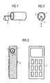
- the structure of a known vibrator is in Figures 1 and 2 shown.
- the vibrator has an electric motor 1, a Rotor shaft 2 and an eccentric weight 3.
- the electric motor 1 sets the rotor shaft 2 in motion, whereby the weight 3 rotates around the rotor shaft and a vibration movement caused in the terminal.
- the location of the mobile device it is desirable to know the location of the mobile device to know. For example, it is conceivable for one a collar at the level of the chest worn by a mobile device, the representation on the display panel of the mobile radio terminal depending on the location of the mobile terminal.
- microelectromechanical motion sensors MEMS (Microelectromechanical Motion Sensors)
- MEMS Microelectromechanical Motion Sensors
- the present invention is therefore based on the object to enable a position detection of a terminal, this should be realized inexpensively and space-saving.
- the vibrator instructs a motor with a rotor shaft weight attached to the rotor shaft to generate vibration and means for determining the orientation of the weight on. In a rest position, this is directed to the rotor shaft Weight always in the direction of the gravitational force Earth out.
- the orientation of the weight is used to determine the position by the gravitational force of the earth in the direction of rotation determined around the rotor shaft in comparison to a predetermined position. By evaluating the current orientation of the The rotor axis or the weight can determine the relative position of the end device to the surface can be detected.
- the Weight movable lengthways along the rotor axis be, with a stop detection on both sides of the rotor axis can be provided ..
- the evaluation of the direction of rotation or the relative Position of the rotor to the rotor can be such on the rotor shaft attached sliding contacts.
- the Means for determining a light barrier can also be determined optically become.
- the Means for determining an incremental disc Over the increment disc position detection can also take place, where an incremental disc has a higher resolution in terms of the current angle of rotation or inclination.
- the Means for determining a Hall sensor With help of a Hall sensor is in turn a position detection possible a rough detection, i.e. a detection of two different ones Positions of the magnetized eccentric weight, is possible.
- the weight interacts with the rotor shaft in such a way that an alignment of the weight towards the gravitational force the earth is possible and the weight does not overshoot.
- the weight must be when the vibrator moves can swing freely.
- the engine must be designed in this way be that it is in rotation when inactive the rotor shaft or the weight attached to the rotor shaft allows. Accordingly, an overshoot of the weight be excluded. Under overshoot understood that the rotor shaft is not in the weight which can turn freely so that it settles into a rest position takes too long.
- the vibrator must therefore be designed in this way be that an optimum between too free and not possible swinging is achieved.
- the terminal is preferably a mobile radio terminal.
- the terminal has a vibrator according to the invention on, depending on the particular orientation of the Weight of the vibrator initiates an action in the terminal becomes.
- the terminal is on one Collar around the neck of a user and the device is on the chest, so the device recognizes with the help of the vibrator, when the user picks up the device and rotates.
- the display on the display device accordingly of the end device rotated by 180 °.
- a menu control of the terminal in Depends on the particular orientation of the weight of the Vibrators a menu control of the terminal.
- the certain Alignment can be detected in which direction the user has moved the mobile device. If there is one double position detection, i.e. a position detection around the rotor axis and along the longitudinal axis of the rotor, so is one Menu control via the position detection is conceivable. Is possible also the movement of a cursor on the display of the end device by a corresponding movement of the terminal.
- the present invention enables an inexpensive and space-saving position detection. All new available on the market Mobile radio terminals have a vibrator for signaling of calls to. In the present invention thus components that are present in every mobile radio terminal are used to perform an additional function.
- FIGS. 1 and 2 show a known vibrator and have been already described in the introduction to the description.
- reference symbols have the same name again the same meaning.
- FIG. 3 shows a schematic representation of a mobile Terminal 4, in which a vibrator with a motor 1, a Rotor shaft 2 and an eccentric weight 3 integrated is. This depends on the location of the mobile terminal 4 Weight along the gravitational force of the earth g.
- Figure 4 shows an orientation of the weight 3 at a Swiveling a mobile device 4.
- the weight 3 judges in both cases along the Earth's gravitational force g off.
- Figure 5 shows two mobile terminals 4 with a display device 5, a so-called “display”, and a cursor 6.
- Figure 5 shows a top view of the horizontal Swiveling according to Figure 4.
- the left representation shows the Cursor 6 on the end device down and the display shows a legible representation of the lettering.
- the lettering rotates 180 ° accordingly and cursor 6 points in the other direction. A corresponding Change therefore takes place due to the change in position.
- FIG. 6 again shows a vibrator in the left representation, the right illustration shows how a change in position can be detected in a further plane can.
- the rotor axis is again in the right illustration 2 connected to the electric motor 1, the eccentric Weight 3 is attached to the rotor shaft.
- a movement of the weight along the rotor axis 2 possible, as indicated by the double arrow 7 is indicated.
- a stop detection can be used for position detection left or right (not shown) provided his. Other options for position detection are conceivable.
- Figure 7 shows a schematic representation of a movement of the vibrator according to Figure 6.
- the inclination shown in FIG. 7 moves the weight 3 along the rotor shaft 2 in the direction 8.
- the movements can in turn can be detected via a stop detection.
- the position detections according to FIGS. 4 and 7 can also can be combined so that, for example, a movement of a Cursors on a display in all directions becomes.
Landscapes
- Engineering & Computer Science (AREA)
- Power Engineering (AREA)
- Microelectronics & Electronic Packaging (AREA)
- Physics & Mathematics (AREA)
- General Physics & Mathematics (AREA)
- Radar, Positioning & Navigation (AREA)
- Remote Sensing (AREA)
- Apparatuses For Generation Of Mechanical Vibrations (AREA)
Abstract
Description
- Figur 1
- eine schematische Darstellung eines Vibrators;
- Figur 2
- eine schematische Darstellung eines Vibrators in Frontansicht;
- Figur 3
- eine schematische Darstellung eines in einem mobilen Endgerät integrierten Vibrators;
- Figur 4
- eine schematische Darstellung einer horizontalen Schwenkung eines mobilen Endgeräts bei entsprechender Lage des Vibrators;
- Figur 5
- eine schematische Darstellung eines Ausführungsbeispiels für die Umschaltung der Ausgabevorrichtung und Steuerung eines Cursors;
- Figur 6
- eine schematische Darstellung eines Vibrators in Vorderansicht und Seitenansicht; und
- Figur 7
- eine schematische Darstellung der Achsenbewegung eines Vibrators bei entsprechender Neigung zur Detektierung einer weiteren Lageänderung in einer weiteren Ebene.
Claims (11)
- Vibrator, aufweisend:gekennzeichnet durcheinen Motor (1) mit einer Rotorwelle (2), undein an der Rotorwelle angebrachtes Gewicht (3) zum Erzeugen einer Vibration,
Mittel zum Bestimmen der Ausrichtung des Gewichts. - Vibrator nach Anspruch 1,
dadurch gekennzeichnet, dass
die Ausrichtung des Gewichts durch die Gravitationskraft der Erde in Drehrichtung um die Rotorwelle im Vergleich zu einer vorgegebenen Lage bestimmt wird. - Vibrator nach einem der vorhergehenden Ansprüche,
dadurch gekennzeichnet, dass
die Ausrichtung des Gewichts durch die Gravitationskraft der Erde in Längsrichtung entlang der Rotorwelle im Vergleich zu einer vorgegebenen Lage bestimmt wird. - Vibrator nach einem der vorhergehenden Ansprüche,
dadurch gekennzeichnet, dass
die Mittel zum Bestimmen mehrere an der Rotorwelle angebrachte Schleifkontakte aufweisen. - Vibrator nach einem der vorhergehenden Ansprüche,
dadurch gekennzeichnet, dass
die Mittel zum Bestimmen eine Lichtschranke aufweisen. - Vibrator nach einem der vorhergehenden Ansprüche,
dadurch gekennzeichnet, dass
die Mittel zum Bestimmen eine Inkrementscheibe aufweisen. - Vibrator nach einem der vorhergehenden Ansprüche,
dadurch gekennzeichnet, dass
die Mittel zum Bestimmen einen Hallsensor aufweisen. - Vibrator nach einem der vorhergehenden Ansprüche,
dadurch gekennzeichnet, dass
das Gewicht mit der Rotorwelle derart zusammenwirkt, dass eine Ausrichtung des Gewichts in Richtung der Gravitationskraft der Erde möglich ist, und das Gewicht nicht überschwingt. - Endgerät, insbesondere Mobilfunk-Endgerät, mit einem Vibrator nach einem der vorhergehenden Ansprüche,
dadurch gekennzeichnet, dass
in Abhängigkeit von der bestimmten Ausrichtung des Gewichts des Vibrators eine Aktion in dem Endgerät initiiert wird. - Endgerät nach Anspruch 9,
dadurch gekennzeichnet, dass
in Abhängigkeit von der bestimmten Ausrichtung des Gewichts des Vibrators die Darstellung der Anzeigevorrichtung (5) des Endgeräts um 180° gedreht wird. - Endgerät nach Anspruch 9 oder 10,
dadurch gekennzeichnet, dass
in Abhängigkeit von der bestimmten Ausrichtung des Gewichts des Vibrators eine Menüsteuerung des Endgeräts erfolgt.
Priority Applications (1)
| Application Number | Priority Date | Filing Date | Title |
|---|---|---|---|
| EP02014719A EP1378984A1 (de) | 2002-07-03 | 2002-07-03 | Vibrator mit integrierter Positionsbestimmung |
Applications Claiming Priority (1)
| Application Number | Priority Date | Filing Date | Title |
|---|---|---|---|
| EP02014719A EP1378984A1 (de) | 2002-07-03 | 2002-07-03 | Vibrator mit integrierter Positionsbestimmung |
Publications (1)
| Publication Number | Publication Date |
|---|---|
| EP1378984A1 true EP1378984A1 (de) | 2004-01-07 |
Family
ID=29719712
Family Applications (1)
| Application Number | Title | Priority Date | Filing Date |
|---|---|---|---|
| EP02014719A Withdrawn EP1378984A1 (de) | 2002-07-03 | 2002-07-03 | Vibrator mit integrierter Positionsbestimmung |
Country Status (1)
| Country | Link |
|---|---|
| EP (1) | EP1378984A1 (de) |
Citations (3)
| Publication number | Priority date | Publication date | Assignee | Title |
|---|---|---|---|---|
| DE3215284A1 (de) | 1982-04-20 | 1983-10-27 | Oelsch KG, 1000 Berlin | Neigungsgeber |
| EP1104143A2 (de) | 1999-11-29 | 2001-05-30 | Nokia Mobile Phones Ltd. | Tragbare Vorrichtungen |
| FR2812225A1 (fr) | 2000-07-26 | 2002-02-01 | Moving Magnet Tech | Vibreur pour telephone portable |
-
2002
- 2002-07-03 EP EP02014719A patent/EP1378984A1/de not_active Withdrawn
Patent Citations (3)
| Publication number | Priority date | Publication date | Assignee | Title |
|---|---|---|---|---|
| DE3215284A1 (de) | 1982-04-20 | 1983-10-27 | Oelsch KG, 1000 Berlin | Neigungsgeber |
| EP1104143A2 (de) | 1999-11-29 | 2001-05-30 | Nokia Mobile Phones Ltd. | Tragbare Vorrichtungen |
| FR2812225A1 (fr) | 2000-07-26 | 2002-02-01 | Moving Magnet Tech | Vibreur pour telephone portable |
Similar Documents
| Publication | Publication Date | Title |
|---|---|---|
| EP1167109B1 (de) | Anwahlschalteinrichtung | |
| WO2005050683A1 (de) | Bedienelement mit programmierbarer haptik | |
| DE3818456A1 (de) | Sicherheitsvorrichtung fuer eine automatisch bewegte fensterscheibe eines kraftfahrzeugs | |
| DE3115630A1 (de) | Geschwindigkeits-aenderungssensor | |
| EP1269068B1 (de) | Vorrichtung zum drehen eines körpers um zwei achsen | |
| WO2002097223A1 (de) | Vorrichtung zur anzeige des schliesszustandes eines schlosses | |
| DE102011085146A1 (de) | Bedienelement mit magnetischer Rückstellung | |
| DE3941651A1 (de) | Antriebsvorrichtung fuer bewegbare baueinheiten | |
| DE102005062862A1 (de) | Vorrichtung zur Erfassung der Drehrichtung eines einen Elektromotor aufweisenden Handwerkszeugs | |
| DE102012201498A1 (de) | Bedienvorrichtung und Verfahren zum Betrieb einer Bedienvorrichtung | |
| WO2001008409A1 (de) | Mobiles bildtelefon | |
| DE2823745C2 (de) | ||
| EP0830567B1 (de) | Kompass mit einer neigungskompensierenden anzeigeeinrichtung | |
| EP1385082A1 (de) | Eingabevorrichtung für ein Endgerät | |
| DE9100654U1 (de) | Drehmoment-Überlastungsanzeige | |
| DE10001676C1 (de) | Elektronischer Umdrehungszähler | |
| DE3542563A1 (de) | Sensorvorrichtung fuer die winkelstellung der antriebseinheit einer schiffsantriebsvorrichtung | |
| DE2928328C2 (de) | Diebstahlsicherung für Fahrzeuge | |
| DE10031096C2 (de) | Anwahlschalteinrichtung | |
| DE102017111865A1 (de) | Bedienvorrichtung zum Bedienen zumindest eines Geräts eines Kraftfahrzeugs, wobei eine Drehstellung eines Bedienelements abhängig von einem Magnetfeld erfassbar ist, Kraftfahrzeug sowie Verfahren | |
| DE102023118452B3 (de) | Vorrichtung zur Erfassung der Schnittlänge einer Haarschneidevorrichtung und Haarschneidevorrichtung aufweisend eine solche Vorrichtung | |
| DE102015207856A1 (de) | Drehratensensor und Verfahren | |
| EP1333452B1 (de) | Steuereinrichtung für einen Motor zur Verstellung eines Stellorgans | |
| DE102019107324A1 (de) | Positionserfassungsanordnung für durch eine Antriebsvorrichtung verfahrbare Türen oder Tore | |
| WO2004068925A1 (de) | Aufsetz-positioniervorrichtung zum aufsetzen von objekten auf substrate |
Legal Events
| Date | Code | Title | Description |
|---|---|---|---|
| PUAI | Public reference made under article 153(3) epc to a published international application that has entered the european phase |
Free format text: ORIGINAL CODE: 0009012 |
|
| AK | Designated contracting states |
Kind code of ref document: A1 Designated state(s): AT BE BG CH CY CZ DE DK EE ES FI FR GB GR IE IT LI LU MC NL PT SE SK TR |
|
| AX | Request for extension of the european patent |
Extension state: AL LT LV MK RO SI |
|
| 17P | Request for examination filed |
Effective date: 20040119 |
|
| AKX | Designation fees paid |
Designated state(s): DE FR GB |
|
| RAP1 | Party data changed (applicant data changed or rights of an application transferred) |
Owner name: BENQ MOBILE GMBH & CO. OHG |
|
| 19U | Interruption of proceedings before grant |
Effective date: 20070101 |
|
| 19W | Proceedings resumed before grant after interruption of proceedings |
Effective date: 20070702 |
|
| 19W | Proceedings resumed before grant after interruption of proceedings |
Effective date: 20090803 |
|
| RAP1 | Party data changed (applicant data changed or rights of an application transferred) |
Owner name: PALM, INC. |
|
| RAP1 | Party data changed (applicant data changed or rights of an application transferred) |
Owner name: HEWLETT-PACKARD DEVELOPMENT COMPANY, L.P. |
|
| 17Q | First examination report despatched |
Effective date: 20130521 |
|
| GRAP | Despatch of communication of intention to grant a patent |
Free format text: ORIGINAL CODE: EPIDOSNIGR1 |
|
| INTG | Intention to grant announced |
Effective date: 20140122 |
|
| RAP1 | Party data changed (applicant data changed or rights of an application transferred) |
Owner name: QUALCOMM INCORPORATED |
|
| STAA | Information on the status of an ep patent application or granted ep patent |
Free format text: STATUS: THE APPLICATION IS DEEMED TO BE WITHDRAWN |
|
| 18D | Application deemed to be withdrawn |
Effective date: 20140603 |