EP1378919A2 - Flachbandkabel - Google Patents
Flachbandkabel Download PDFInfo
- Publication number
- EP1378919A2 EP1378919A2 EP03011195A EP03011195A EP1378919A2 EP 1378919 A2 EP1378919 A2 EP 1378919A2 EP 03011195 A EP03011195 A EP 03011195A EP 03011195 A EP03011195 A EP 03011195A EP 1378919 A2 EP1378919 A2 EP 1378919A2
- Authority
- EP
- European Patent Office
- Prior art keywords
- ribbon cable
- beads
- cable according
- insulating sleeve
- electrical conductors
- Prior art date
- Legal status (The legal status is an assumption and is not a legal conclusion. Google has not performed a legal analysis and makes no representation as to the accuracy of the status listed.)
- Granted
Links
Images

Classifications
-
- H—ELECTRICITY
- H01—ELECTRIC ELEMENTS
- H01B—CABLES; CONDUCTORS; INSULATORS; SELECTION OF MATERIALS FOR THEIR CONDUCTIVE, INSULATING OR DIELECTRIC PROPERTIES
- H01B7/00—Insulated conductors or cables characterised by their form
- H01B7/08—Flat or ribbon cables
-
- H—ELECTRICITY
- H01—ELECTRIC ELEMENTS
- H01B—CABLES; CONDUCTORS; INSULATORS; SELECTION OF MATERIALS FOR THEIR CONDUCTIVE, INSULATING OR DIELECTRIC PROPERTIES
- H01B7/00—Insulated conductors or cables characterised by their form
- H01B7/17—Protection against damage caused by external factors, e.g. sheaths or armouring
- H01B7/18—Protection against damage caused by wear, mechanical force or pressure; Sheaths; Armouring
- H01B7/184—Sheaths comprising grooves, ribs or other projections
Definitions
- the present invention relates to a ribbon cable, in particular a clock spring, with at least two electrical conductors, the electrical conductors in an insulating sleeve are embedded and the insulating sleeve has a substantially rectangular cross section and the ribbon cable can be wound up, so that two of the Surfaces of the insulating sleeve come to lie on one another.
- Clock springs are for use in motor vehicles known. They serve a reliable electrical Connection between a rotating steering wheel and a relative to the motor vehicle stationary steering wheel mount create.
- the one used for the electrical connection Ladder is also known as a clock spring.
- This Clock spring is coil-shaped in a housing between the Steering wheel and the steering wheel holder coiled and such dimensioned that the steering wheel one in both directions can perform a complete rotation of several revolutions, without this rotation path through the length of the clock spring is limited.
- Such arrangements are, for example, from known from DE 195 34 655 A1 and DE 198 37 076 A1.
- Cavities are formed by the surface structure, in condensed moisture can. This ensures that the aforementioned Adhesive effect between the surfaces of the insulating sleeve is significantly reduced.
- the surface structure according to the invention causes the Surfaces of the insulating sleeve only in parts of the Total area come to lie on each other. This will capillary forces are also reduced or avoided entirely. Consequently, an adhesive effect can only be in these Sub-areas arise.
- a Ribbon cable a first surface (top) with a Surface structure and a second, flat surface (Bottom) on. It is also possible that the top and the underside has a surface structure.
- the surface structure advantageous that the surface is uneven, and for example, has depressions or recesses which are formed in this surface. It is special advantageous that the recesses or recesses in Longitudinal direction of the electrical conductors. This has the main advantage of using the clock spring of extrusion processes can be made, wherein the recesses or recesses are part of the endless profile of the ribbon cable.
- the depressions or Recesses are also funnel-shaped or spherical are.
- This form of training has the advantage that the Surfaces of the insulating sleeve only in the between the Recesses or recesses formed with edge areas the contact surface of the insulating sleeve come. This can greatly reduce the contact area become.
- the protrusions are in the surface of the insulating sleeve Projections formed. Even through these protrusions the contact area between the superimposed ones Surfaces of the insulating sleeve of the ribbon cable strong be reduced.
- the protrusions are in Form of pimples or ridges formed in cross section
- the protrusions are formed as nubs Contact area from those areas of the knobs that in relation to a knob in the middle and therefore most elevated are.
- this can Ribbon cables using extrusion processes be produced if the beads in the longitudinal direction of the electrical conductors.
- the beads can be part the common insulating sleeve of several electrical conductors be stamped into the insulating sleeve. It is also possible, that the beads are formed by the electrical conductors each have their own electrical Have insulation that are in the longitudinal direction with each other are welded. In such an embodiment forms thus part of the insulating sleeve of an electrical conductor a bead.
- the beads can be transverse to the longitudinal direction of the electrical conductors. Even through one Embodiment can the contact area between the superimposed surfaces of the ribbon cable be reduced. This is also possible if the beads run at an angle between the longitudinal and the Transverse direction of the electrical conductor is formed.
- the beads are So on the top and bottom of the ribbon cable arranged. Touch when winding the ribbon cable the beads on a top face with the beads on one Underside of an adjacent winding only in Crossing points. This arrangement also ensures that Contact area between adjacent surfaces reduced.
- the ribbon cable 2 has a Substantially rectangular cross section on that of an essentially flat underside 4, an uneven one Top 6 and a first boundary 8 and one second boundary 10 is limited.
- the ribbon cable 2 has insulating material 12 that as a sheath for the in Longitudinal direction of the ribbon cable 2 extending electrical conductor 14 is used.
- Embodiment are a total of five electrical conductors shown.
- In the uneven top 6 are total three substantially rectangular depressions 16 introduced, which is in the longitudinal direction of the ribbon cable 2 extend.
- the depressions 16 serve as a receiving space for moisture that is due to a Temperature changes from a cold to a warm state from moist ambient air on the ribbon cable 2 reflected. This wet precipitation can occur in the Wells 16 are added.
- the uneven top 6 has elevation surfaces 18 which as a support surface for a not shown in Figure 1 serve flat bottom 4 of the same ribbon cable 2, which is wound in the form of a snail or spiral.
- FIG. 2 shows an embodiment of a ribbon cable 20, the left hand in a top view and the right hand in a cross section is shown.
- the ribbon cable 20 is delimited by a flat underside 24, an uneven one Top side 26 and first and second borders 28 and 30.
- the ribbon cable 20 consists of insulating material 32 for in this embedded electrical conductor 34.
- In the top 26 of the ribbon cable 20 are spherical depressions 36 arranged in which there is precipitated moisture can collect.
- the ribbon cable shown in Figure 2 comes with Rewinding with raised areas 38 in the top 26 a first winding with the underside 24 of a second Winding in contact.
- the whole from the survey areas 38 formed surface is opposite to that on the underside 24 formed area small. This will make the danger reduced that the ribbon cable 20 when precipitation of Moisture sticks to an adjacent winding.
- FIG 3 is a designated 40 in total Ribbon cable on the left in a top view and shown on the right in a cross section.
- the Ribbon cable 40 has a substantially flat Bottom 44, an uneven top 46 and one Borders 48 and 50 respectively.
- the ribbon cable 40 consists of an insulating material 52 into the electrical conductor 54 are embedded.
- On the top 46 of the ribbon cable 40 are knob-shaped projections or elevations 56 intended.
- the knobs 56 have a part-circular shape Cross section on and limit water collection rooms 58. In In these rooms, this can be done by condensing water formed in humid air, which prevents will that the top 46 of a first winding of the Ribbon cable 40 on the underside 44 of an adjacent one Winding sticks.
- the ribbon cable 60 shown in Figure 4 has one Similar structure to that shown in Figure 3 Ribbon cable 40 on. However, the ribbon cable 60 has not spherical segment-shaped knobs 56, but honeycomb-shaped Pimples 76 on. There are water collecting spaces between the knobs 76 78 trained.
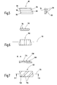
- FIG 5 is a top view on the left and right hand a cross section of a ribbon cable 80 is shown.
- the Ribbon cable 80 has a total of three beads 96 that in the longitudinal direction of the electrical conductor 94 of the Ribbon cable 80 run.
- the ridges 96 have one partly circular cross-section. Are between them Water collection rooms 98 are also formed in Longitudinal direction of the electrical conductor 94 of the Ribbon cable 80 run.
- the ribbon cable 120 shown in Figure 7 is in the in Figure 7 lower drawing in a plan view and in in Figure 7 top drawing along the cross section B-B shown.
- the ribbon cable 120 has a cross section trapezoidal beads 136 which are inclined to 139 designated longitudinal direction of the in the ribbon cable 120 trending electrical conductor. Between trapezoidal beads 136 are water collection spaces 138 educated.
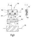
- the ribbon cable 140 shown in Figure 8 is on the left in the top drawing in a top view, in the middle drawing in a side view and in the bottom drawing shown in a bottom view.
- Figure 8 on the right is a cross section along the line C-C shown according to the drawing on the left.
- the Ribbon cable 140 has both on the bottom 144 and 146 beads on the top, each at an angle to the longitudinal direction of the ribbon cable designated 159 140 run.
- On top 146 there are beads 156 and 144 beads 155 arranged on the underside. Between the Top 146 and bottom 144 located Insulating material 152 is used to hold electrical Ladders 154.
- FIG Surfaces of adjacent windings only in Crossing areas 157 of the beads 155 and 156 for support.
- the intersection areas 157 are shown hatched.
Landscapes
- Insulated Conductors (AREA)
Abstract
Description
- Figur 1
- ein Flachbandkabel mit in Längsrichtung der elektrischen Leiter vorgesehenen Vertiefungen;
- Figur 2
- ein Flachbandkabel mit sphärischen Vertiefungen;
- Figur 3
- ein Flachbandkabel mit noppenförmigen Vorsprüngen gemäß einer ersten Ausführungsform;
- Figur 4
- ein Flachbandkabel mit noppenförmigen Vorsprüngen gemäß einer zweiten Ausführungsform;
- Figur 5
- ein Flachbandkabel mit in Längsrichtung der elektrischen Leiter verlaufenden Vorsprüngen in Form von Wülsten;
- Figur 6
- ein Flachbandkabel mit quer zur Längsrichtung der elektrischen Leiter verlaufenden Wülsten; und
- Figur 7
- ein Flachbandkabel mit trapezförmigen Wülsten, die zwischen der Längs- und der Querrichtung der elektrischen Leiter verlaufen.
- Figur 8
- ein Flachbandkabel mit auf Ober- und Unterseite angeordneten Wülsten.
Claims (13)
- Flachbandkabel (2), insbesondere Wickelfeder, mit mindestens zwei elektrischen Leitern (14), wobei die elektrischen Leiter (14) in einer Isolierhülle (12) eingebettet sind und die Isolierhülle (12) einen im Wesentlichen rechteckförmigen Querschnitt aufweist und das Flachbandkabel (2) aufwickelbar ist, so dass zwei der Oberflächen (4, 6) der Isolierhülle (12) aufeinander zu liegen kommen, dadurch gekennzeichnet, dass wenigstens eine der Oberflächen (6) eine Oberflächenstruktur aufweist.
- Flachbandkabel nach Anspruch 1, dadurch gekennzeichnet, dass die Oberfläche (6) uneben ist.
- Flachbandkabel nach einem der vorhergehenden Ansprüche, dadurch gekennzeichnet, dass in der Oberfläche (6) Vertiefungen oder Ausnehmungen (16) ausgebildet sind.
- Flachbandkabel nach Anspruch 4, dadurch gekennzeichnet, dass die Vertiefungen oder Ausnehmungen (16) in Längsrichtung der elektrischen Leiter (14) verlaufen.
- Flachbandkabel nach Anspruch 4 oder 5, dadurch gekennzeichnet, dass Vertiefungen oder Ausnehmungen trichterförmig oder sphärisch (36) ausgebildet sind.
- Flachbandkabel nach einem der vorhergehenden Ansprüche, dadurch gekennzeichnet, dass in der Oberfläche der Isolierhülle Vorsprünge ausgebildet sind.
- Flachbandkabel nach Anspruch 6, dadurch gekennzeichnet, dass die Vorsprünge in Form von Noppen (56, 76) gebildet sind.
- Flachbandkabel nach Anspruch 6 oder 7, dadurch gekennzeichnet, dass die Vorsprünge in Form von Wülsten (96, 116, 136) gebildet sind.
- Flachbandkabel nach Anspruch 7 oder 8, dadurch gekennzeichnet, dass die Noppen (56, 76) oder Wülste (96, 116, 136) im Querschnitt teilkreisförmig (56, 96, 116) oder prismatisch (76, 136) sind.
- Flachbandkabel nach Anspruch 8 oder 9, dadurch gekennzeichnet, dass die Wülste (96) in Längsrichtung der elektrischen Leiter (94) verlaufen.
- Flachbandkabel nach Anspruch 8 oder 9, dadurch gekennzeichnet, dass die Wülste (116) quer zur Längsrichtung (119) der elektrischen Leiter verlaufen.
- Flachbandkabel nach Anspruch 8 oder 9, dadurch gekennzeichnet, dass die Wülste (136) in einem Winkel verlaufen, der zwischen der Längs- (139) und der Querrichtung der elektrischen Leiter gebildet ist.
- Flachbandkabel nach Anspruch 12, dadurch gekennzeichnet, dass die Wülste auf zwei der aufeinander zu liegen kommenden Oberflächen der Isolierhülle angeordnet sind, wobei die Wülste (155, 156), wenn sie aufeinander liegen, einen von 0° abweichenden Winkel einschließen, insbesondere einen Winkel von größer 0° bis 90°.
Applications Claiming Priority (2)
| Application Number | Priority Date | Filing Date | Title |
|---|---|---|---|
| DE10230348 | 2002-07-02 | ||
| DE2002130348 DE10230348A1 (de) | 2002-07-02 | 2002-07-02 | Flachbandkabel |
Publications (3)
| Publication Number | Publication Date |
|---|---|
| EP1378919A2 true EP1378919A2 (de) | 2004-01-07 |
| EP1378919A3 EP1378919A3 (de) | 2004-01-28 |
| EP1378919B1 EP1378919B1 (de) | 2012-10-24 |
Family
ID=29719481
Family Applications (1)
| Application Number | Title | Priority Date | Filing Date |
|---|---|---|---|
| EP20030011195 Expired - Lifetime EP1378919B1 (de) | 2002-07-02 | 2003-05-28 | Wickelfeder |
Country Status (2)
| Country | Link |
|---|---|
| EP (1) | EP1378919B1 (de) |
| DE (1) | DE10230348A1 (de) |
Cited By (1)
| Publication number | Priority date | Publication date | Assignee | Title |
|---|---|---|---|---|
| EP2477195A3 (de) * | 2011-01-18 | 2013-04-24 | Feller GmbH | Kabeltrommelkabel |
Citations (6)
| Publication number | Priority date | Publication date | Assignee | Title |
|---|---|---|---|---|
| US3700825A (en) | 1970-10-01 | 1972-10-24 | Int Computers Ltd | Circuit interconnecting cables and methods of making such cables |
| GB1304601A (de) | 1970-04-29 | 1973-01-24 | ||
| FR2452769A1 (fr) | 1979-03-24 | 1980-10-24 | Nkf Groep Bv | Cable plat electrique flexible, son procede de fabrication et sa disposition |
| DE19534655A1 (de) | 1995-09-19 | 1997-03-20 | Teves Gmbh Alfred | Transportsystem für einen aufgewickelten elektrischen Leiter mit Wickelsinnumkehrung durch Schleifenbildung |
| DE19837076A1 (de) | 1998-08-17 | 2000-02-24 | Kostal Leopold Gmbh & Co Kg | Vorrichtung zum Erfassen einer vordefinierten absoluten Nullstellung zwischen einem Rotor und einem Stator sowie Verwendung |
| FR2802906A1 (fr) | 1999-12-22 | 2001-06-29 | Stemmann Technik Gmbh | Faisceau flexible de cables et touret a cables ou a conduits destine a recevoir le faisceau de cables |
Family Cites Families (7)
| Publication number | Priority date | Publication date | Assignee | Title |
|---|---|---|---|---|
| DE362153C (de) * | 1922-10-23 | Electro Agricultur Aktiebolage | Stromzufuehrungskabel fuer sich bewegende elektrische Maschinen | |
| DE656546C (de) * | 1938-02-08 | Buckau R Wolf Akt Ges Maschf | Elektrisches Stromzufuehrungskabel, insbesondere fuer Trockenbagger | |
| BE502214A (de) * | 1950-03-30 | |||
| DE2646373A1 (de) * | 1976-10-14 | 1978-04-20 | Reinshagen Kabelwerk Gmbh | Elektrische flachleitung |
| US4409431A (en) * | 1981-08-07 | 1983-10-11 | Harvey Hubbell Incorporated | Oil well cable |
| US6026563A (en) * | 1996-04-03 | 2000-02-22 | Methode Electronics, Inc. | Method of making flat cable |
| US6006000A (en) * | 1998-02-17 | 1999-12-21 | Hubbell Incorporated | Composite ribbon coupling cable for rotary coupling apparatus |
-
2002
- 2002-07-02 DE DE2002130348 patent/DE10230348A1/de not_active Withdrawn
-
2003
- 2003-05-28 EP EP20030011195 patent/EP1378919B1/de not_active Expired - Lifetime
Patent Citations (6)
| Publication number | Priority date | Publication date | Assignee | Title |
|---|---|---|---|---|
| GB1304601A (de) | 1970-04-29 | 1973-01-24 | ||
| US3700825A (en) | 1970-10-01 | 1972-10-24 | Int Computers Ltd | Circuit interconnecting cables and methods of making such cables |
| FR2452769A1 (fr) | 1979-03-24 | 1980-10-24 | Nkf Groep Bv | Cable plat electrique flexible, son procede de fabrication et sa disposition |
| DE19534655A1 (de) | 1995-09-19 | 1997-03-20 | Teves Gmbh Alfred | Transportsystem für einen aufgewickelten elektrischen Leiter mit Wickelsinnumkehrung durch Schleifenbildung |
| DE19837076A1 (de) | 1998-08-17 | 2000-02-24 | Kostal Leopold Gmbh & Co Kg | Vorrichtung zum Erfassen einer vordefinierten absoluten Nullstellung zwischen einem Rotor und einem Stator sowie Verwendung |
| FR2802906A1 (fr) | 1999-12-22 | 2001-06-29 | Stemmann Technik Gmbh | Faisceau flexible de cables et touret a cables ou a conduits destine a recevoir le faisceau de cables |
Cited By (1)
| Publication number | Priority date | Publication date | Assignee | Title |
|---|---|---|---|---|
| EP2477195A3 (de) * | 2011-01-18 | 2013-04-24 | Feller GmbH | Kabeltrommelkabel |
Also Published As
| Publication number | Publication date |
|---|---|
| EP1378919A3 (de) | 2004-01-28 |
| DE10230348A1 (de) | 2004-01-15 |
| EP1378919B1 (de) | 2012-10-24 |
Similar Documents
| Publication | Publication Date | Title |
|---|---|---|
| DE19604797C2 (de) | Drehbare Verbindungseinrichtung | |
| DE3534653C2 (de) | ||
| DE102013002740A1 (de) | Flachkabel mit gerillter und planter Oberfläche | |
| DE60010985T2 (de) | Steckverbinder für Kabelbäume | |
| EP0425846B1 (de) | Vorrichtung zur Stromübertragung zwischen zwei Endstellen | |
| DE2243034B1 (de) | Elektrische kontaktanordnung | |
| WO2007131706A1 (de) | Elektrisch betreibbare flächenheizelement-anordnung, insbesondere als fussboden-flächenheizelement-anordnung | |
| DE10018680A1 (de) | Kontaktschienenanordnung | |
| DE2408959B2 (de) | Kabelbaum | |
| DE102009030645A1 (de) | Brückerelement und Set aus Klemmelement und Brückerelement | |
| DE1765978B1 (de) | Schaltungsblock zum elektrischen verbinden mittels steck verbindungen von elektrischen schaltungselementen | |
| EP0387585A1 (de) | Flacchkabelspirale | |
| EP0991151A2 (de) | Kontaktelement zur Verbindung einer Flachbandleitung mit Rundleitern und Drehverbinder mit einem derartigen Kontaktelement | |
| EP0254770B1 (de) | Elektrische Kontaktvorrichtung | |
| DE29813561U1 (de) | Verlängerungsvorrichtung für Dekorationslampen | |
| EP2270820A2 (de) | Stromkabel und Stromversorgungseinrichtung | |
| DE10230348A1 (de) | Flachbandkabel | |
| EP1349180B1 (de) | Elektrische Flachleiter-Bandleitung | |
| WO2011131303A1 (de) | Elektrischer anschluss | |
| DE19946130A1 (de) | Anordnung zum Kontaktieren eines Flachfolienleiters einer Folie | |
| EP0289707B1 (de) | Elektrisches Heizelement mit Abgriff | |
| DE19944427A1 (de) | Kabelverbindung zwischen Flachbandkabel und Rundbandkabel bzw. Rundkabel und Verfahren zu deren Herstellung | |
| DE2416578A1 (de) | Vorrichtung zur vorfertigung einer einbau-waermeaustauschstruktur. | |
| DE19508259C2 (de) | Drehverbinder | |
| WO2008087067A1 (de) | Elektrische spule mit mehreren windungslagen |
Legal Events
| Date | Code | Title | Description |
|---|---|---|---|
| PUAI | Public reference made under article 153(3) epc to a published international application that has entered the european phase |
Free format text: ORIGINAL CODE: 0009012 |
|
| PUAL | Search report despatched |
Free format text: ORIGINAL CODE: 0009013 |
|
| AK | Designated contracting states |
Kind code of ref document: A2 Designated state(s): AT BE BG CH CY CZ DE DK EE ES FI FR GB GR HU IE IT LI LU MC NL PT RO SE SI SK TR |
|
| AX | Request for extension of the european patent |
Extension state: AL LT LV MK |
|
| AK | Designated contracting states |
Kind code of ref document: A3 Designated state(s): AT BE BG CH CY CZ DE DK EE ES FI FR GB GR HU IE IT LI LU MC NL PT RO SE SI SK TR |
|
| AX | Request for extension of the european patent |
Extension state: AL LT LV MK |
|
| 17P | Request for examination filed |
Effective date: 20040623 |
|
| AKX | Designation fees paid |
Designated state(s): DE FR GB IT |
|
| 17Q | First examination report despatched |
Effective date: 20100318 |
|
| REG | Reference to a national code |
Ref country code: DE Ref legal event code: R079 Ref document number: 50314549 Country of ref document: DE Free format text: PREVIOUS MAIN CLASS: H01B0007080000 Ipc: H01B0007180000 |
|
| RIC1 | Information provided on ipc code assigned before grant |
Ipc: H01B 7/08 20060101ALI20120329BHEP Ipc: H01B 7/18 20060101AFI20120329BHEP |
|
| RTI1 | Title (correction) |
Free format text: BUFFER SPRING |
|
| GRAP | Despatch of communication of intention to grant a patent |
Free format text: ORIGINAL CODE: EPIDOSNIGR1 |
|
| GRAS | Grant fee paid |
Free format text: ORIGINAL CODE: EPIDOSNIGR3 |
|
| GRAA | (expected) grant |
Free format text: ORIGINAL CODE: 0009210 |
|
| AK | Designated contracting states |
Kind code of ref document: B1 Designated state(s): DE FR GB IT |
|
| REG | Reference to a national code |
Ref country code: GB Ref legal event code: FG4D Free format text: NOT ENGLISH |
|
| RAP2 | Party data changed (patent owner data changed or rights of a patent transferred) |
Owner name: VALEO SCHALTER UND SENSOREN GMBH |
|
| REG | Reference to a national code |
Ref country code: DE Ref legal event code: R096 Ref document number: 50314549 Country of ref document: DE Effective date: 20121220 |
|
| PG25 | Lapsed in a contracting state [announced via postgrant information from national office to epo] |
Ref country code: IT Free format text: LAPSE BECAUSE OF FAILURE TO SUBMIT A TRANSLATION OF THE DESCRIPTION OR TO PAY THE FEE WITHIN THE PRESCRIBED TIME-LIMIT Effective date: 20121024 |
|
| PLBE | No opposition filed within time limit |
Free format text: ORIGINAL CODE: 0009261 |
|
| STAA | Information on the status of an ep patent application or granted ep patent |
Free format text: STATUS: NO OPPOSITION FILED WITHIN TIME LIMIT |
|
| 26N | No opposition filed |
Effective date: 20130725 |
|
| REG | Reference to a national code |
Ref country code: DE Ref legal event code: R097 Ref document number: 50314549 Country of ref document: DE Effective date: 20130725 |
|
| GBPC | Gb: european patent ceased through non-payment of renewal fee |
Effective date: 20130528 |
|
| PG25 | Lapsed in a contracting state [announced via postgrant information from national office to epo] |
Ref country code: DE Free format text: LAPSE BECAUSE OF NON-PAYMENT OF DUE FEES Effective date: 20131203 |
|
| REG | Reference to a national code |
Ref country code: DE Ref legal event code: R119 Ref document number: 50314549 Country of ref document: DE Effective date: 20131203 |
|
| REG | Reference to a national code |
Ref country code: FR Ref legal event code: ST Effective date: 20140131 |
|
| PG25 | Lapsed in a contracting state [announced via postgrant information from national office to epo] |
Ref country code: GB Free format text: LAPSE BECAUSE OF NON-PAYMENT OF DUE FEES Effective date: 20130528 |
|
| PG25 | Lapsed in a contracting state [announced via postgrant information from national office to epo] |
Ref country code: FR Free format text: LAPSE BECAUSE OF NON-PAYMENT OF DUE FEES Effective date: 20130531 |