EP1378632B1 - Easy-fit heat screening device for connecting a cooling pipe and a through-hole formed in a nozzle support ring of a gas turbine - Google Patents
Easy-fit heat screening device for connecting a cooling pipe and a through-hole formed in a nozzle support ring of a gas turbine Download PDFInfo
- Publication number
- EP1378632B1 EP1378632B1 EP03254222.7A EP03254222A EP1378632B1 EP 1378632 B1 EP1378632 B1 EP 1378632B1 EP 03254222 A EP03254222 A EP 03254222A EP 1378632 B1 EP1378632 B1 EP 1378632B1
- Authority
- EP
- European Patent Office
- Prior art keywords
- hole
- screening device
- support ring
- nozzle support
- heat screening
- Prior art date
- Legal status (The legal status is an assumption and is not a legal conclusion. Google has not performed a legal analysis and makes no representation as to the accuracy of the status listed.)
- Expired - Lifetime
Links
Images


Classifications
-
- F—MECHANICAL ENGINEERING; LIGHTING; HEATING; WEAPONS; BLASTING
- F02—COMBUSTION ENGINES; HOT-GAS OR COMBUSTION-PRODUCT ENGINE PLANTS
- F02C—GAS-TURBINE PLANTS; AIR INTAKES FOR JET-PROPULSION PLANTS; CONTROLLING FUEL SUPPLY IN AIR-BREATHING JET-PROPULSION PLANTS
- F02C7/00—Features, components parts, details or accessories, not provided for in, or of interest apart form groups F02C1/00 - F02C6/00; Air intakes for jet-propulsion plants
- F02C7/28—Arrangement of seals
-
- F—MECHANICAL ENGINEERING; LIGHTING; HEATING; WEAPONS; BLASTING
- F01—MACHINES OR ENGINES IN GENERAL; ENGINE PLANTS IN GENERAL; STEAM ENGINES
- F01D—NON-POSITIVE DISPLACEMENT MACHINES OR ENGINES, e.g. STEAM TURBINES
- F01D9/00—Stators
- F01D9/06—Fluid supply conduits to nozzles or the like
- F01D9/065—Fluid supply or removal conduits traversing the working fluid flow, e.g. for lubrication-, cooling-, or sealing fluids
-
- F—MECHANICAL ENGINEERING; LIGHTING; HEATING; WEAPONS; BLASTING
- F01—MACHINES OR ENGINES IN GENERAL; ENGINE PLANTS IN GENERAL; STEAM ENGINES
- F01D—NON-POSITIVE DISPLACEMENT MACHINES OR ENGINES, e.g. STEAM TURBINES
- F01D11/00—Preventing or minimising internal leakage of working-fluid, e.g. between stages
- F01D11/005—Sealing means between non relatively rotating elements
-
- F—MECHANICAL ENGINEERING; LIGHTING; HEATING; WEAPONS; BLASTING
- F01—MACHINES OR ENGINES IN GENERAL; ENGINE PLANTS IN GENERAL; STEAM ENGINES
- F01D—NON-POSITIVE DISPLACEMENT MACHINES OR ENGINES, e.g. STEAM TURBINES
- F01D25/00—Component parts, details, or accessories, not provided for in, or of interest apart from, other groups
- F01D25/08—Cooling; Heating; Heat-insulation
Definitions
- the present invention refers to an easy-fit heat screening device for connecting a cooling pipe and a through-hole formed in a nozzle support ring of a gas turbine.
- gas turbines are machines consisting of a compressor and single or multiple-stage turbine, where these components are connected together by a rotating shaft and where a combustion chamber is provided between the compressor and the turbine.
- the pressurised air passes through a series of pre-mixing chambers which terminate in a converging portion and inside each of which an injector feeds the fuel which is mixed with the air so as to form an air/burning fuel mixture.
- the fuel is introduced inside the combustion chamber and is ignited by means of suitable sparking plugs so as to produce combustion which is aimed at causing an increase in temperature and pressure and therefore enthalpy of the gas.
- the compressor supplies pressurised air which is made to pass both through the burners and through the casing of the combustion chamber so that the abovementioned pressurised air is available for fuelling the combustion.
- the high-temperature and high-pressure gas reaches, via suitable ducts, the different stages of the turbine which converts the enthalpy of the gas into mechanical energy which is available to the user.
- cooling pipes are used for this purpose, said pipes conveying a cooling air which is supplied from the compressor and having, for example, to pass through the nozzles of the first low-pressure stage (which are thus provided with suitable holes) and through the nozzle support ring, in order to reach the zones to be pressurised.
- the air which is tapped from the compressor has a temperature which is considerably lower than the operating temperature of the nozzle support ring.
- heat screening devices In order to avoid - in the zones where the cooling pipes pass through a through-hole formed in the nozzle support ring - the spread of high temperatures inside the said support ring, heat screening devices have been introduced.
- These devices are arranged between the cooling pipe and the through-hole of the nozzle support ring and comprise a tubular structure.
- these tubular structures also perform another function. In fact they act as a seat for the cooling pipe and ensure a sealed connection with the through-hole formed in the nozzle support ring.
- the cooling pipe which generally has spherical ends, departs from an external casing of the turbine and terminates inside the through-hole of the nozzle support ring.
- the seat for the spherical end of the cooling pipe is provided by a bush inserted from the outside of the nozzle support ring and locked with a ring nut on the inside of the ring itself. This is possible when the through-holes passing through the nozzle support ring are straight, there being only one zone where pressurisation is to be performed.
- the through-holes passing through the nozzle support ring are of two types: one which is straight and the other inclined.
- two different types of fixing devices are used, one for straight holes and one for inclined holes, using also two different fixing methods.
- US 5,517,817 discloses a variable area turbine nozzle for use in a turbine engine.
- the variable area turbine nozzle adjusts the positions of its vanes to insure efficient operation of the turbine engine.
- a flanged bushing which has a tubular structure has an end which is inserted in a groove at one end of a first housing of a cooling chamber, a second housing of the cooling chamber being placed above and displaced from the first housing.
- the present invention therefore seeks to overcome the abovementioned drawbacks and in particular that of providing an easy-fit heat screening device for connecting a cooling pipe and a through-hole formed in a nozzle support ring of a gas turbine which can be applied equally well to straight holes and inclined holes.
- the present invention also seeks to provide an easy-fit heat screening device for connecting a cooling pipe and a through-hole formed in an nozzle support ring of a gas turbine which allows a reduction in production and maintenance costs compared to the prior art.
- the present invention further seeks to provide an easy-fit heat screening device for connecting a cooling pipe and a through-hole formed in a nozzle support ring of a gas turbine which is particularly reliable, simple and functional.
- a heat screening device according to the prior art is indicated overall by 10, said device being intended to join together a cooling pipe 12 and straight through-hole 14 formed in a nozzle support ring 16 of a gas turbine.
- the screening device 10 comprises a tubular structure 18 having a top end 20 with an external diameter approximately equal to an internal diameter of the through-hole 14.
- This tubular structure 18 is inserted from the outside of the nozzle support ring 16 and is arranged at a bottom end of the through-hole 14, being locked there by a ring nut 22 mounted on the inside of the said ring 16 so as to support the overlying tubular structure 18.
- a bottom - generally spherical - end of the cooling pipe 12 extends inside the tubular structure 18.
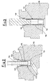
- FIGS 2, 3 , 4 and 5 illustrate an easy-fit heat screening device 110, according to the present invention, for connecting a cooling pipe 112 and a through-hole 114 formed in a nozzle support ring 116 of a gas turbine, where components identical/or equivalent to those illustrated in Figure 1 have the same reference numbers increased of 100.
- Figure 2 shows a through-hole 114 having two sections inclined with respect to each other, whereas Figure 3 shows a straight through-hole 114.
- an upper zone of the through-hole 114 has a groove 130.
- the groove 130 is defined at the bottom by a first flat surface 132 which is substantially perpendicular to the axis of this upper zone and at the top by a second surface 134 having an inclination along a line directed towards an outer extension of the first surface 132.
- the upper zone of the through-hole 114 has, above the groove 130, a first internal diameter greater than a second internal diameter provided underneath the said groove 130.
- the screening device 110 comprises a tubular structure 118.
- This tubular structure 118 is inserted from the outside of the nozzle support ring 116 and is arranged inside the through-hole 114.
- the tubular structure 118 has at the bottom an annular end 124 with an external diameter which is approximately equal to the second internal diameter of the through-hole 114.
- the tubular structure 118 has a shaped annular end 126.
- an external surface of the shaped annular end 126 is formed with two different diameters.
- a first external cylindrical surface 128 is provided, said surface having a diameter slightly smaller than the first internal diameter of the through-hole 114.
- a second external cylindrical surface 129 is provided, with a diameter slightly smaller than the second internal diameter of the through-hole 114.
- the first external cylindrical surface 128 is joined to the second external cylindrical surface 129 by a flat annular surface 127 which extends substantially perpendicularly with respect to the axis of the upper zone of the through-hole 114.
- the shaped annular end 126 terminates at the top in a surface 125, having an inclination along a line directed towards an outer extension of the flat annular surface 127.
- a bottom - generally spherical - end of the cooling pipe 112 extends inside the tubular structure 118.
- the heat screening device 110 is inserted, from outside of the nozzle support ring 116, into the upper zone of the through-hole 114. Insertion is performed so that the flat annular surface 127 mates with the first flat surface 132 of the groove 130.
- the shaped annular end 126 is engaged inside the groove 130.
- the shaped annular end 126 is bent, as can be seen in Figure 3 , using for example a mounting tool with a conical end which is inserted from the outside of the nozzle support ring 116.
- the shaped annular end 126 enters partly inside the groove 130; in particular, the surface 125 of the shaped annular end 126 engages in an interfering manner with part of the second surface 134.
- the first external cylindrical surface 128 is designed with dimensions suitable for this purpose: the inclination of the second surface 134 is also approximately parallel to the inclination of the surface 125 of the shaped annular end 126 such that, after bending of the shaped annular end 126, the surface 125 makes firm contact with the second surface 134.
- the heat screening device 110 advantageously uses an oil-hydraulic apparatus equipped with the conical-end mounting tool and able to generate a thrust, for example, of 10,000 Newton.
- the material from which the heat screening device 110 according to the invention is made must have, in addition to heat resistance characteristics, also good plastic deformation properties required for bending of the shaped annular end 126.
Landscapes
- Engineering & Computer Science (AREA)
- Mechanical Engineering (AREA)
- General Engineering & Computer Science (AREA)
- Physics & Mathematics (AREA)
- Fluid Mechanics (AREA)
- Chemical & Material Sciences (AREA)
- Combustion & Propulsion (AREA)
- Turbine Rotor Nozzle Sealing (AREA)
Applications Claiming Priority (2)
| Application Number | Priority Date | Filing Date | Title |
|---|---|---|---|
| ITMI20021465 | 2002-07-03 | ||
| IT2002MI001465A ITMI20021465A1 (it) | 2002-07-03 | 2002-07-03 | Dispositivo di schermatura termica di facile montaggio per un accoppiamento tra una tubazione di raffreddamento ed una foratura passante rea |
Publications (3)
| Publication Number | Publication Date |
|---|---|
| EP1378632A2 EP1378632A2 (en) | 2004-01-07 |
| EP1378632A3 EP1378632A3 (en) | 2005-11-23 |
| EP1378632B1 true EP1378632B1 (en) | 2015-03-11 |
Family
ID=11450134
Family Applications (1)
| Application Number | Title | Priority Date | Filing Date |
|---|---|---|---|
| EP03254222.7A Expired - Lifetime EP1378632B1 (en) | 2002-07-03 | 2003-07-02 | Easy-fit heat screening device for connecting a cooling pipe and a through-hole formed in a nozzle support ring of a gas turbine |
Country Status (8)
| Country | Link |
|---|---|
| US (1) | US6890147B2 (enExample) |
| EP (1) | EP1378632B1 (enExample) |
| JP (1) | JP4307920B2 (enExample) |
| KR (1) | KR100790627B1 (enExample) |
| CN (1) | CN100520012C (enExample) |
| CA (1) | CA2432816C (enExample) |
| IT (1) | ITMI20021465A1 (enExample) |
| NO (1) | NO20033033L (enExample) |
Families Citing this family (11)
| Publication number | Priority date | Publication date | Assignee | Title |
|---|---|---|---|---|
| DE102004014117A1 (de) * | 2004-03-23 | 2005-10-13 | Alstom Technology Ltd | Komponente einer Turbomaschine mit einer Kühlanordnung |
| GB0508912D0 (en) * | 2005-04-30 | 2005-06-08 | Rolls Royce Plc | Vane coupling |
| US8596959B2 (en) * | 2009-10-09 | 2013-12-03 | Pratt & Whitney Canada Corp. | Oil tube with integrated heat shield |
| US9316117B2 (en) | 2012-01-30 | 2016-04-19 | United Technologies Corporation | Internally cooled spoke |
| US9316153B2 (en) * | 2013-01-22 | 2016-04-19 | Siemens Energy, Inc. | Purge and cooling air for an exhaust section of a gas turbine assembly |
| EP2933436A1 (de) * | 2014-04-15 | 2015-10-21 | Siemens Aktiengesellschaft | Radscheibe mit wenigstens einem Dichtblech |
| US9920869B2 (en) | 2014-05-22 | 2018-03-20 | United Technologies Corporation | Cooling systems for gas turbine engine components |
| US9790860B2 (en) * | 2015-01-16 | 2017-10-17 | United Technologies Corporation | Cooling passages for a mid-turbine frame |
| PL421120A1 (pl) | 2017-04-04 | 2018-10-08 | General Electric Company Polska Spolka Z Ograniczona Odpowiedzialnoscia | Silnik turbinowy i części składowe do stosowania w nim |
| FR3101372B1 (fr) * | 2019-09-27 | 2021-10-01 | Safran Aircraft Engines | Turbomachine d’aeronef |
| US11692485B2 (en) | 2021-02-18 | 2023-07-04 | Generai, Electric Company | Gas turbine engine with spoolie fluid transfer connection |
Family Cites Families (10)
| Publication number | Priority date | Publication date | Assignee | Title |
|---|---|---|---|---|
| US3370830A (en) * | 1966-12-12 | 1968-02-27 | Gen Motors Corp | Turbine cooling |
| US3574354A (en) * | 1969-05-08 | 1971-04-13 | Avica Corp | Flexible coupling |
| US5224818A (en) | 1991-11-01 | 1993-07-06 | General Electric Company | Air transfer bushing |
| US5517817A (en) * | 1993-10-28 | 1996-05-21 | General Electric Company | Variable area turbine nozzle for turbine engines |
| US6217279B1 (en) | 1997-06-19 | 2001-04-17 | Mitsubishi Heavy Industries, Ltd. | Device for sealing gas turbine stator blades |
| JP3564290B2 (ja) * | 1997-12-24 | 2004-09-08 | 三菱重工業株式会社 | 蒸気冷却型ガスタービン |
| ITMI991208A1 (it) * | 1999-05-31 | 2000-12-01 | Nuovo Pignone Spa | Dispositivo per il posizionamento di ugelli di uno stadio statorico eper il raffreddamento di dischi rotorici in turbine a gas |
| US6382906B1 (en) * | 2000-06-16 | 2002-05-07 | General Electric Company | Floating spoolie cup impingement baffle |
| JP2002155703A (ja) | 2000-11-21 | 2002-05-31 | Mitsubishi Heavy Ind Ltd | ガスタービン静翼−翼環間蒸気通路のシール構造 |
| ITMI20020910A1 (it) * | 2002-04-29 | 2003-10-29 | Nuovo Pignone Spa | Dispositivo di tenuta per accoppiamento di una tubazione con un foro |
-
2002
- 2002-07-03 IT IT2002MI001465A patent/ITMI20021465A1/it unknown
-
2003
- 2003-06-19 CA CA2432816A patent/CA2432816C/en not_active Expired - Fee Related
- 2003-06-30 US US10/608,553 patent/US6890147B2/en not_active Expired - Lifetime
- 2003-07-01 JP JP2003189148A patent/JP4307920B2/ja not_active Expired - Lifetime
- 2003-07-02 EP EP03254222.7A patent/EP1378632B1/en not_active Expired - Lifetime
- 2003-07-02 KR KR1020030044496A patent/KR100790627B1/ko not_active Expired - Lifetime
- 2003-07-02 NO NO20033033A patent/NO20033033L/no unknown
- 2003-07-03 CN CNB03145304XA patent/CN100520012C/zh not_active Expired - Lifetime
Also Published As
| Publication number | Publication date |
|---|---|
| KR100790627B1 (ko) | 2007-12-31 |
| US20040057825A1 (en) | 2004-03-25 |
| CN1495341A (zh) | 2004-05-12 |
| US6890147B2 (en) | 2005-05-10 |
| NO20033033L (no) | 2004-01-05 |
| CA2432816A1 (en) | 2004-01-03 |
| ITMI20021465A0 (it) | 2002-07-03 |
| EP1378632A2 (en) | 2004-01-07 |
| JP2004052765A (ja) | 2004-02-19 |
| ITMI20021465A1 (it) | 2004-01-05 |
| CA2432816C (en) | 2010-11-09 |
| JP4307920B2 (ja) | 2009-08-05 |
| EP1378632A3 (en) | 2005-11-23 |
| CN100520012C (zh) | 2009-07-29 |
| KR20040004125A (ko) | 2004-01-13 |
| NO20033033D0 (no) | 2003-07-02 |
Similar Documents
| Publication | Publication Date | Title |
|---|---|---|
| US11662095B2 (en) | Fuel nozzle and combustor and gas turbine including the same | |
| EP1378632B1 (en) | Easy-fit heat screening device for connecting a cooling pipe and a through-hole formed in a nozzle support ring of a gas turbine | |
| CN102644918A (zh) | 用于在燃烧器中安装过渡件的方法和设备 | |
| US10934864B2 (en) | Apparatus for axial locking of bucket and bucket assembly and gas turbine having the same | |
| US20220228741A1 (en) | Nozzle assembly, combustor, and gas turbine having same | |
| CN113154391B (zh) | 一种气氧气甲烷火炬点火装置及其火炬生成方法 | |
| KR20190108955A (ko) | 가스 터빈 연료 공급 장치, 이를 구비한 연료 노즐 및 가스 터빈 | |
| CN107975820A (zh) | 燃烧器空气罩组件及燃烧器组件 | |
| US11608985B2 (en) | Combustor and gas turbine including the same | |
| JP4424553B2 (ja) | ジェットバーナー | |
| CN107869392A (zh) | 用于燃气涡轮发动机流体管路的安装组件 | |
| KR102047369B1 (ko) | 연료 노즐, 이를 포함하는 연소기 및 가스 터빈 | |
| EP3477203B1 (en) | Combustor and gas turbine including the same | |
| US11846419B2 (en) | Dome-deflector joint cooling arrangement | |
| KR20200004455A (ko) | 연료 노즐, 이를 포함하는 연소기 및 가스 터빈 | |
| JP2020201033A (ja) | 火炎伝播管設置/取り外し方法および装置 | |
| KR102021128B1 (ko) | 연소기 및 이를 포함하는 가스 터빈 | |
| KR102021129B1 (ko) | 연료 노즐, 이를 포함하는 연소기 및 가스 터빈 | |
| JP4646039B2 (ja) | 高圧および低圧タービンの内部領域を分離させる構造 | |
| KR20220104493A (ko) | 노즐 어셈블리, 연소기 및 이를 포함하는 가스터빈 | |
| KR102047368B1 (ko) | 연료 노즐, 이를 포함하는 연소기 및 가스 터빈 | |
| US11060727B2 (en) | Fuel nozzle assembly and gas turbine including the same | |
| KR101842745B1 (ko) | 가스터빈의 트랜지션피스와 터빈의 결합장치 | |
| WO2002027169A1 (en) | A connecting device | |
| KR20190133129A (ko) | 연소기 및 이를 포함하는 가스 터빈 |
Legal Events
| Date | Code | Title | Description |
|---|---|---|---|
| PUAI | Public reference made under article 153(3) epc to a published international application that has entered the european phase |
Free format text: ORIGINAL CODE: 0009012 |
|
| AK | Designated contracting states |
Kind code of ref document: A2 Designated state(s): AT BE BG CH CY CZ DE DK EE ES FI FR GB GR HU IE IT LI LU MC NL PT RO SE SI SK TR |
|
| AX | Request for extension of the european patent |
Extension state: AL LT LV MK |
|
| PUAL | Search report despatched |
Free format text: ORIGINAL CODE: 0009013 |
|
| AK | Designated contracting states |
Kind code of ref document: A3 Designated state(s): AT BE BG CH CY CZ DE DK EE ES FI FR GB GR HU IE IT LI LU MC NL PT RO SE SI SK TR |
|
| AX | Request for extension of the european patent |
Extension state: AL LT LV MK |
|
| RIC1 | Information provided on ipc code assigned before grant |
Ipc: 7F 01D 25/08 B Ipc: 7F 01D 9/06 A Ipc: 7F 01D 11/00 B |
|
| 17P | Request for examination filed |
Effective date: 20060523 |
|
| AKX | Designation fees paid |
Designated state(s): CH DE FR GB LI NL |
|
| 17Q | First examination report despatched |
Effective date: 20060915 |
|
| 17Q | First examination report despatched |
Effective date: 20060915 |
|
| GRAP | Despatch of communication of intention to grant a patent |
Free format text: ORIGINAL CODE: EPIDOSNIGR1 |
|
| INTG | Intention to grant announced |
Effective date: 20141020 |
|
| GRAS | Grant fee paid |
Free format text: ORIGINAL CODE: EPIDOSNIGR3 |
|
| GRAA | (expected) grant |
Free format text: ORIGINAL CODE: 0009210 |
|
| AK | Designated contracting states |
Kind code of ref document: B1 Designated state(s): CH DE FR GB LI NL |
|
| REG | Reference to a national code |
Ref country code: GB Ref legal event code: FG4D |
|
| REG | Reference to a national code |
Ref country code: CH Ref legal event code: EP |
|
| REG | Reference to a national code |
Ref country code: DE Ref legal event code: R096 Ref document number: 60347391 Country of ref document: DE Effective date: 20150423 |
|
| REG | Reference to a national code |
Ref country code: FR Ref legal event code: PLFP Year of fee payment: 13 |
|
| PGFP | Annual fee paid to national office [announced via postgrant information from national office to epo] |
Ref country code: NL Payment date: 20150726 Year of fee payment: 13 |
|
| PGFP | Annual fee paid to national office [announced via postgrant information from national office to epo] |
Ref country code: CH Payment date: 20150914 Year of fee payment: 13 |
|
| PGFP | Annual fee paid to national office [announced via postgrant information from national office to epo] |
Ref country code: FR Payment date: 20150717 Year of fee payment: 13 |
|
| REG | Reference to a national code |
Ref country code: DE Ref legal event code: R097 Ref document number: 60347391 Country of ref document: DE |
|
| PLBE | No opposition filed within time limit |
Free format text: ORIGINAL CODE: 0009261 |
|
| STAA | Information on the status of an ep patent application or granted ep patent |
Free format text: STATUS: NO OPPOSITION FILED WITHIN TIME LIMIT |
|
| 26N | No opposition filed |
Effective date: 20151214 |
|
| REG | Reference to a national code |
Ref country code: CH Ref legal event code: PL |
|
| REG | Reference to a national code |
Ref country code: NL Ref legal event code: MM Effective date: 20160801 |
|
| PG25 | Lapsed in a contracting state [announced via postgrant information from national office to epo] |
Ref country code: CH Free format text: LAPSE BECAUSE OF NON-PAYMENT OF DUE FEES Effective date: 20160731 Ref country code: LI Free format text: LAPSE BECAUSE OF NON-PAYMENT OF DUE FEES Effective date: 20160731 Ref country code: NL Free format text: LAPSE BECAUSE OF NON-PAYMENT OF DUE FEES Effective date: 20160801 Ref country code: FR Free format text: LAPSE BECAUSE OF NON-PAYMENT OF DUE FEES Effective date: 20160801 |
|
| REG | Reference to a national code |
Ref country code: FR Ref legal event code: ST Effective date: 20170331 |
|
| REG | Reference to a national code |
Ref country code: GB Ref legal event code: 732E Free format text: REGISTERED BETWEEN 20220414 AND 20220420 |
|
| PGFP | Annual fee paid to national office [announced via postgrant information from national office to epo] |
Ref country code: GB Payment date: 20220621 Year of fee payment: 20 |
|
| REG | Reference to a national code |
Ref country code: GB Ref legal event code: 732E Free format text: REGISTERED BETWEEN 20220728 AND 20220803 |
|
| PGFP | Annual fee paid to national office [announced via postgrant information from national office to epo] |
Ref country code: DE Payment date: 20220621 Year of fee payment: 20 |
|
| REG | Reference to a national code |
Ref country code: DE Ref legal event code: R071 Ref document number: 60347391 Country of ref document: DE |
|
| REG | Reference to a national code |
Ref country code: GB Ref legal event code: PE20 Expiry date: 20230701 |
|
| PG25 | Lapsed in a contracting state [announced via postgrant information from national office to epo] |
Ref country code: GB Free format text: LAPSE BECAUSE OF EXPIRATION OF PROTECTION Effective date: 20230701 |