EP1378146B1 - Expandable in-ear device - Google Patents
Expandable in-ear device Download PDFInfo
- Publication number
- EP1378146B1 EP1378146B1 EP02701132.9A EP02701132A EP1378146B1 EP 1378146 B1 EP1378146 B1 EP 1378146B1 EP 02701132 A EP02701132 A EP 02701132A EP 1378146 B1 EP1378146 B1 EP 1378146B1
- Authority
- EP
- European Patent Office
- Prior art keywords
- platform
- sheath
- defining
- distal end
- core
- Prior art date
- Legal status (The legal status is an assumption and is not a legal conclusion. Google has not performed a legal analysis and makes no representation as to the accuracy of the status listed.)
- Expired - Lifetime
Links
- 210000002445 nipple Anatomy 0.000 claims description 33
- 210000000613 ear canal Anatomy 0.000 claims description 32
- 238000002347 injection Methods 0.000 claims description 29
- 239000007924 injection Substances 0.000 claims description 29
- 239000000463 material Substances 0.000 claims description 27
- 150000001875 compounds Chemical class 0.000 claims description 20
- 238000004891 communication Methods 0.000 claims description 15
- 238000011065 in-situ storage Methods 0.000 claims description 10
- 239000012528 membrane Substances 0.000 claims description 10
- 239000012530 fluid Substances 0.000 claims description 3
- 239000007787 solid Substances 0.000 claims description 3
- 239000002861 polymer material Substances 0.000 claims description 2
- 238000011161 development Methods 0.000 description 2
- 229920001296 polysiloxane Polymers 0.000 description 2
- 208000032041 Hearing impaired Diseases 0.000 description 1
- 230000005540 biological transmission Effects 0.000 description 1
- 230000000295 complement effect Effects 0.000 description 1
- 230000001419 dependent effect Effects 0.000 description 1
- 230000000694 effects Effects 0.000 description 1
- 238000005516 engineering process Methods 0.000 description 1
- 239000003292 glue Substances 0.000 description 1
- 238000003780 insertion Methods 0.000 description 1
- 230000037431 insertion Effects 0.000 description 1
- 238000009434 installation Methods 0.000 description 1
- 230000014759 maintenance of location Effects 0.000 description 1
- 238000004519 manufacturing process Methods 0.000 description 1
- 238000005259 measurement Methods 0.000 description 1
- 238000000034 method Methods 0.000 description 1
- 238000010295 mobile communication Methods 0.000 description 1
- 238000012986 modification Methods 0.000 description 1
- 230000004048 modification Effects 0.000 description 1
- 238000000465 moulding Methods 0.000 description 1
- 238000012545 processing Methods 0.000 description 1
Images
Classifications
-
- H—ELECTRICITY
- H04—ELECTRIC COMMUNICATION TECHNIQUE
- H04R—LOUDSPEAKERS, MICROPHONES, GRAMOPHONE PICK-UPS OR LIKE ACOUSTIC ELECTROMECHANICAL TRANSDUCERS; DEAF-AID SETS; PUBLIC ADDRESS SYSTEMS
- H04R25/00—Deaf-aid sets, i.e. electro-acoustic or electro-mechanical hearing aids; Electric tinnitus maskers providing an auditory perception
- H04R25/65—Housing parts, e.g. shells, tips or moulds, or their manufacture
- H04R25/652—Ear tips; Ear moulds
- H04R25/656—Non-customized, universal ear tips, i.e. ear tips which are not specifically adapted to the size or shape of the ear or ear canal
-
- H—ELECTRICITY
- H04—ELECTRIC COMMUNICATION TECHNIQUE
- H04R—LOUDSPEAKERS, MICROPHONES, GRAMOPHONE PICK-UPS OR LIKE ACOUSTIC ELECTROMECHANICAL TRANSDUCERS; DEAF-AID SETS; PUBLIC ADDRESS SYSTEMS
- H04R25/00—Deaf-aid sets, i.e. electro-acoustic or electro-mechanical hearing aids; Electric tinnitus maskers providing an auditory perception
- H04R25/65—Housing parts, e.g. shells, tips or moulds, or their manufacture
- H04R25/658—Manufacture of housing parts
- H04R25/659—Post-processing of hybrid ear moulds for customisation, e.g. in-situ curing
Definitions
- the present invention generally relates to in-ear devices such as earplugs, hearing aid devices and the like, and more particularly, to custom-fitting in-ear devices that are formed in-situ to perfectly assume the inside of the ear canal and cavum concha of an individual.
- HPDs Hearing protection devices
- HPDs are often passive (i.e. not powered) and some simply amount to a plug in the ear; while more sophisticated (but still passive) HPDs may include acoustic chambers and filters, for passing or attenuating selected frequencies.
- hearing device includes active devices, either of a hearing protection nature, or of a hearing aid nature, in which some or all of the batteries and other components are mounted behind the ear, or remotely, in a box, which communicates with the in-ear unit by means of a sound-tube, or by wires; and includes active devices in which a microphone, speaker, and all the associated sound-processing circuitry and components, including a battery, are contained within the in-ear unit.
- HPDs like hearing aids
- Canadian patent application No. 2,302,962/A1 of McIntosh et al. filed on March 23, 2000 and laid open on September 26, 2000 discloses a hearing apparatus adapted to be inflated in-situ using an inflation-medium.
- the apparatus includes a core portion that is generally covered by a separate sheath.
- the proper installation of the sheath requires extensive delicate care, especially when bonding the far end of the sheath to the core using the far-seal-means without obstructing the acoustic tube.
- An advantage of the present invention is that the expandable in-ear device can be very properly re-inserted by an individual repeatedly.
- a further advantage of the present invention is that the expandable in-ear device is molded out into a single piece.
- Still another advantage of the present invention is that the expandable in-ear device is customized depending on the user's need to be an earplug, a filtered earplug, a hearing aid device, a communication device or the like.
- Still a further advantage of the present invention is that the expandable in-ear device is comfortable for users.
- the expandable in-ear device is adaptable to be side specific, either a left or righthand-side device.
- the expandable in-ear device is customized depending on the user's need to releasably receive any type of communication device therein.
- an expandable in-ear device for being custom fitted in-situ of an ear canal of an individual by injection of a settable compound material therein, the device comprises:
- the platform distal end periphery defines a platform protruding surface, the platform protruding surface protruding outwardly from the platform distal end and defining a protruding surface perimeter, the sheath aperture having a shape to assume the surface perimeter.
- the sheath is a thin and stretchable polymer material with substantially no inherent structural rigidity.
- the core-form is generally solid with a material hardness value of less than thirty (30) shore-A.
- the sheath tightly assumes the core-form when in the folded configuration as to have the in-between region being substantially fluidless.
- the in-ear device is made out of a.single molded piece.
- the protruding surface perimeter defines a perimeter groove extending therealong, the sheath aperture defining an aperture perimeter, the aperture perimeter being reinforced with a integral bulge tightly engaging the perimeter groove when in the folded configuration so as to substantially close off the in-between region.
- the sound bore is a first sound bore
- the platform section defining a cavity substantially extending inwardly therein from the protruding surface, whereby the cavity is for removably, tightly and at least partially house an insert member therein
- the core-form further defining a second sound bore generally extending from the nipple proximal end to the cavity through both of the nipple and platform sections for conducting sound from the cavity to inside of the ear canal, whereby the insert member is in sound communication with inside of the ear canal via the second sound bore.
- the cavity includes an insert retaining means for releasably retaining the insert member therein.
- the platform distal end includes a slit membrane temporarily closing off the sound bore, the slit membrane allows for a remote instrument to be releasably inserted therethrough to get in communication with the sound bore.
- the device includes a handle member secured to the platform section adjacent the platform distal end for handling the in-ear device.
- the platform section includes an injection slit channel substantially extending therethrough between the platform distal end to the in-between region to be in fluid communication therewith, the injection slit channel for releasably receiving part of an injection device therein to inject the settable compound material therethrough into the in-between region.
- the injection slit channel is generally rectilinear, the handle member being generally elongated and defines a longitudinal reach-through hole being substantially in-line with the injection slit channel of the platform section, the reach-through hole for guiding an injection device containing the settable compound material into the injection slit channel within the platform section.
- the reach-through hole of the handle member includes a close-off membrane at one end thereof, the close-off membrane being in contact with the platform section of the core-form.
- the injection slit channel self closes upon retraction of the injection device therefrom.
- the platform distal end defines a generally convex shape
- the convex shape has a generally elongated apex and is substantially symmetrical thereabout, the convex shape defining two substantially planar surfaces with the elongated apex defining a common distal edge therebetween, the planar surfaces generally extending away from each other from the common distal edge and towards the platform proximal end.
- one of the two surfaces includes the platform distal end periphery defining a platform protruding surface, the platform protruding surface protruding outwardly from the platform distal end and defining a protruding surface perimeter, the sheath aperture having a shape to assume the surface perimeter, the other of the two surfaces being fully covered by the sheath when in the folded configuration to form part of the in-between region for being custom fitted in-situ of a cavum concha of the individual corresponding to the ear canal so as to perfectly assume the cavum concha.
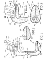
- FIG. 1 to 8 there is shown an embodiment 10 of an expandable in-ear device according to the present invention.
- the device 10 is adapted for being custom fitted in-situ inside the ear canal C and cavum concha V of an individual by injection of a settable compound material 23 therein.
- the device 10 includes a core-form 20 defining a platform section 30 and a nipple section 40 and having a core-form shape.
- the platform section 30 that essentially fits into the cavum concha V defines a platform distal end 32 and a generally opposed platform proximal end 31, the latter defining a platform distal end periphery 34.
- the nipple section 40 that essentially fits into the ear canal C defines a nipple distal end 43 and a generally opposed nipple proximal end 41.
- the nipple section 40 integrally extends from the platform proximal end 31 for engaging the ear canal C.
- a sound bore 21 generally extends from the nipple proximal end 41 to the platform distal end 32 through both the nipple 40 and the platform 30 sections, for conducting sound from an environment to inside of the ear canal C.
- a stretchable sheath 50 shown in Fig. 1 , is integral to and freely extends away from the nipple proximal end 41 of the core-form 20 in an unfolded configuration of the device 10.
- the sheath 50 defines a sheath shape that is substantially a mirror image of the shape of the core-form 20.
- the sheath 50 is configured and sized so as to substantially assume the core-form shape when folded inside-out over the core-form 20 in a folded configuration of the device 10.
- the sheath 50 further defines a sheath-to-core-form in-between region 22 when in the folded configuration, as shown in Fig. 3 .
- the sheath 50 has a sheath aperture 51 generally assuming the platform distal end periphery 34.
- the platform section 30 allows for the settable compound material 23 to be injected therethrough to reach the in-between region 22 and stretch the sheath 50 away from the core-form 20 so as to expand the device 10 fitted in the ear canal C such that it perfectly assume and occlude the latter and the cavum concha V, thereby forming a unitary piece with the device 10 after the settable compound material 23 is fully set.
- the in-between region 22 does not communicate with the sound bore 21.
- the in-ear device 10 also preferably includes a handle member 60 secured, preferably glued, to the platform distal end 32.
- the device 10 includes a handle positioning means for positioning the handle 60 relative to the platform section 30.
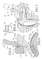
- the handle 60 In order to properly position the handle 60 relative to the core-form 20, the handle 60 preferably has a notch 61 for engaging a corresponding notch recess 33 on the platform section 30, the notch 61 and the notch recess 33 forming the handle positioning means, as shown in Fig. 5 .
- the platform proximal end 31 includes a preferably semi-circular recess 35, adjacent the nipple section 40, as illustrated in Fig. 1 .
- a communicating injection slit channel 36 substantially extends through the platform section 30, between the platform distal end 32 and the semi-circular recess 35 in fluid communication with the in-between region 22.
- the injection slit channel 36 preferably rectilinear, is made to releasably receive a needle N of an injection device such as a syringe S containing the settable compound material 23.
- the injection slit channel 36 is made using a sharp tool perforating the platform 30 prior to folding the sheath 50 over the core-form 20, thereby not damaging the sheath 50.
- the handle 60 is generally elongated and preferably defines a longitudinal reach-through hole 62 to be in-line with the injection slit channel 36 for alternatively guiding the perforating tool and the needle N of the syringe S (shown in dashed lines in Fig. 7 ).
- the hole 62 of the handle 60 is preferably includes a thin close-off membrane 63 at a proximal end thereof getting in contact with the core-form 20 in order to prevent any back flow of glue within the hole 62 when the handle 60 is glued onto the platform 30.
- the injection slit channel 36 is preferably self closing upon retraction of the needle N therefrom.
- the platform distal end periphery 34 defines a platform protruding surface 37 slightly protruding outwardly from the platform distal end 32 and defining a protruding surface perimeter.
- the sheath aperture 51 has a shape to assume the surface perimeter of the platform protruding surface 37.
- the sheath aperture 51 has its perimeter reinforced with a bulge 52 integral therewith for tightly engaging a corresponding groove 38 on the perimeter of the platform protruding surface 37.
- the sheath aperture bulge 52 is preferably bonded (or glued) into the groove 38 of the platform protruding surface 37 to essentially close off the in-between region 22.
- the distal end 21d of the sound bore 21 is located within the platform protruding surface 37 and is preferably terminated by a slit membrane 24 temporarily closing off the same whenever not releasably inserted therethrough by a remote instrument (not shown) such as a microphone of a measurement apparatus or the like.
- the platform distal end 32 preferably defines a generally convex shape with a generally elongated apex 26 and, is substantially symmetrical about the apex 26.
- the convex shape defines two substantially planar surfaces 25 with the apex 26 defining a common distal edge therebetween. Both planar surfaces 25 generally extend downwardly and away from each other from the common distal edge 26 and towards the platform proximal end 31 in a proximal direction.
- Only one of the two surfaces 25 includes the platform distal end periphery 34 defining the platform protruding surface 37 while the other one is fully covered by the sheath 50 in the folded configuration of the in-ear device 10 as to form part of the in-between region 22 that is custom fitted in-situ of a cavum concha V of the individual to perfectly assume the same.
- the device 10 needs a retaining member to prevent it from slidably coming out of the ear canal C. Accordingly, the side of the platform 30 with the surface 25 entirely covered by the sheath 50 is configured and sized to sit into the cavum concha V of the ear and provide the required retention.
- the sheath 50 is progressively folded inside-out over the core-form 20.
- the sheath 50 tightly assumes the core-form 20 such that the in-between region 22 is substantially fluidless, with no air entrapped therein.
- its aperture 51 is bonded all around the protruding surface 37, then the in-between region 22 is typically vacuumed to remove air entrapped therein.
- the device 10 is ready to be inserted into the ear canal C and have the settable compound material 23 injected into the in-between region 22 for the in-situ custom fitting of the in-ear device 10, as shown in Fig. 7 .
- the sheath 50 is then stretched away from the core-form 20 to perfectly assume and occlude the ear canal C.
- the retaining member area of the device 10 also have a simultaneous expansion of its part of the in-between region 22 being filled by the settable compound material so as to perfectly assume the shape of the cavum concha V of the individual.
- the device 10 is then removed from the ear canal C after the compound material 23 is completely set.
- the core-form 20 is generally solid and rigid enough with substantial inherent structural rigidity while the stretchable sheath 50 is a thin material with substantially no inherent structural rigidity, both of them being preferably a single molded piece made out of a silicone type of material or the like with a hardness value of preferably less than thirty (30) shore-A.
- core-form protrusions 42 at the nipple proximal end 41 are present preferably only for molding purposes of the sound bores 21, 28. They are preferably simply chopped off after folding over of the sheath 50; as shown in Figs. 3 and 4 .
- the settable compound material 23 is preferably a rubber-like type material once it is fully cured with a hardness value of preferably less than thirty (30) shore-A.
- the platform section 30 of the in-ear device 10 preferably defines a cavity 27 for removably, tightly and at least partially house an insert member 70 therein considering the fact that the core-form 20 material is substantially resilient.
- the cavity 27 substantially extends inwardly from the protruding surface 37.
- the core-form 20 further defines a second sound bore 28 generally extending from the nipple proximal end 41 to the cavity 27 of the platform 30 through both of the nipple 40 and platform 30 sections for conducting sound from the cavity 27 to inside of the ear canal C such that the insert member 70 can be in sound communication with inside of the ear canal C.
- the second sound bore 28 runs generally parallel to the first one 21 except in the region adjacent the platform distal end 32 where they slightly diverge from each other.
- the cavity preferably includes an insert retaining means for releasably retaining the insert 70 therein.
- the insert retaining means is preferably formed by the lower section of the handle 60 defining a step to be releasably engaged by a complementary locking step 71 of the insert 70.
- Both the handle 60 and the insert 70 are preferably made out of silicone type material or the like having a hardness value typically varying between fifty (50) and eighty (80) shore-A.
- the insert member 70 can be a plug member to simply close off the second sound bore 28, whereby the in-ear device 10 is a typical earplug device.
- the insert member 70 includes a communication element 72 for communicating with the second sound bore 28.
- the communication element 72 can be a band-pass filter, preferably in the form of an adequately sized extension of the second sound bore 28, for allowing an acceptable frequency range to reach inside the ear canal C, whereby the in-ear device 10 is a typical filtered earplug device.
- the communication element 72 of the insert 70a can be an insert cavity 73 adapted to be releasably engaged by an electronic circuit (not shown and well known in the art) or the like for amplifying sound within a pre-determined frequency range from the environment to the second sound bore 28, whereby the in-ear device 10 is a typical hearing aid device, more commonly known as an in-the-ear (ITE) hearing aid.
- ITE in-the-ear
- the communication element 72 could be a simple sound bore extension (not shown) adapted to be engaged by an external hearing aid device, such as a commonly known behind-the-ear (BTE) hearing aid or the like, at a distal end thereof and communicating with the second sound bore 28 at a proximal end thereof, whereby the in-ear device 10 is a typical hearing aid adaptable device.
- an external hearing aid device such as a commonly known behind-the-ear (BTE) hearing aid or the like, at a distal end thereof and communicating with the second sound bore 28 at a proximal end thereof, whereby the in-ear device 10 is a typical hearing aid adaptable device.
- BTE behind-the-ear
- either the communication element 72 or simply the insert member 70 could be a simple audio output connector, being wireless or not, from a typical electronic device such as a computer, a laptop-type computer, a cellular-type (or GSM - Global System for Mobile communications) phone, a hand-held-type (or palm) computer or the like that is adapted to releasably fit within the insert cavity 73.
- a typical electronic device such as a computer, a laptop-type computer, a cellular-type (or GSM - Global System for Mobile communications) phone, a hand-held-type (or palm) computer or the like that is adapted to releasably fit within the insert cavity 73.
- each hole 62 of both handles 60 can be releasably engaged by a respective resilient plug member (not shown) secured to a respective end of a cord or the like, thereby securing both devices 10 together.
Landscapes
- Engineering & Computer Science (AREA)
- Manufacturing & Machinery (AREA)
- Health & Medical Sciences (AREA)
- General Health & Medical Sciences (AREA)
- Neurosurgery (AREA)
- Otolaryngology (AREA)
- Physics & Mathematics (AREA)
- Acoustics & Sound (AREA)
- Signal Processing (AREA)
- Headphones And Earphones (AREA)
- Prostheses (AREA)
- Respiratory Apparatuses And Protective Means (AREA)
Applications Claiming Priority (3)
| Application Number | Priority Date | Filing Date | Title |
|---|---|---|---|
| US09/785,278 US20020114479A1 (en) | 2001-02-20 | 2001-02-20 | Expandable in-ear device |
| PCT/CA2002/000220 WO2002067626A2 (en) | 2001-02-20 | 2002-02-19 | Expandable in-ear device |
| US785278 | 2004-02-24 |
Publications (2)
| Publication Number | Publication Date |
|---|---|
| EP1378146A2 EP1378146A2 (en) | 2004-01-07 |
| EP1378146B1 true EP1378146B1 (en) | 2013-05-29 |
Family
ID=25134969
Family Applications (1)
| Application Number | Title | Priority Date | Filing Date |
|---|---|---|---|
| EP02701132.9A Expired - Lifetime EP1378146B1 (en) | 2001-02-20 | 2002-02-19 | Expandable in-ear device |
Country Status (10)
| Country | Link |
|---|---|
| US (2) | US20020114479A1 (enExample) |
| EP (1) | EP1378146B1 (enExample) |
| JP (1) | JP4125127B2 (enExample) |
| CN (1) | CN100379317C (enExample) |
| AU (1) | AU2002234463B2 (enExample) |
| CA (1) | CA2470238C (enExample) |
| ES (1) | ES2426336T3 (enExample) |
| MX (1) | MXPA03007435A (enExample) |
| WO (1) | WO2002067626A2 (enExample) |
| ZA (1) | ZA200306436B (enExample) |
Families Citing this family (51)
| Publication number | Priority date | Publication date | Assignee | Title |
|---|---|---|---|---|
| DE29918139U1 (de) * | 1999-10-14 | 2000-05-25 | Hörgeräte Seifert GmbH, 81377 München | Otoplastik für Hinter-dem-Ohr (HdO)-Hörgeräte |
| US7664282B2 (en) * | 1998-11-25 | 2010-02-16 | Insound Medical, Inc. | Sealing retainer for extended wear hearing devices |
| US7580537B2 (en) * | 1998-11-25 | 2009-08-25 | Insound Medical, Inc. | Sealing retainer for extended wear hearing devices |
| US20060291683A1 (en) * | 1998-11-25 | 2006-12-28 | Insound Medical, Inc. | Sealing retainer for extended wear hearing devices |
| US20030051277P1 (en) * | 2001-09-07 | 2003-03-13 | Meilland Alain A. | Floribunda rose plant named 'Meizebul' |
| US7227968B2 (en) * | 2001-06-25 | 2007-06-05 | Sonion Roskilde A/S | Expandsible Receiver Module |
| DK1434464T3 (da) * | 2002-12-23 | 2008-08-11 | Sonion Roskilde As | Indkapslet modtager der omfatter et udvideligt organ, såsom en ballon |
| WO2005055650A1 (en) * | 2003-12-05 | 2005-06-16 | Sonomax Hearing Healthcare Inc | In-ear device |
| WO2005079373A2 (en) * | 2004-02-13 | 2005-09-01 | Insound Medical, Inc. | Perforated cap for a hearing aid |
| US7240765B2 (en) * | 2004-08-25 | 2007-07-10 | Phonak Ag | Customized hearing protection earplug with an acoustic filter and method for manufacturing the same |
| US7185734B2 (en) * | 2004-08-25 | 2007-03-06 | Phonak Ag | Hearing protection earplug, use of such an earplug and method for manufacturing such an earplug |
| EP1629804B1 (en) | 2004-08-25 | 2009-02-18 | Phonak Ag | Hearing protection earplug, use of such an earplug and method for manufacturing such an earplug |
| US7369670B2 (en) * | 2004-08-25 | 2008-05-06 | Phonak Ag | Earplug and method for manufacturing the same |
| US7864972B2 (en) * | 2004-10-14 | 2011-01-04 | Sonomax Hearing Healthcare Inc. | Customized in-ear interface for acoustic equipment and method |
| US7401680B2 (en) * | 2004-12-23 | 2008-07-22 | Phonak Ag | Hearing protection earplug and use of the same |
| US7715572B2 (en) * | 2005-02-04 | 2010-05-11 | Solomito Jr Joe A | Custom-fit hearing device kit and method of use |
| US20120057740A1 (en) * | 2006-03-15 | 2012-03-08 | Mark Bryan Rosal | Security and protection device for an ear-mounted audio amplifier or telecommunication instrument |
| US20070217641A1 (en) * | 2006-03-15 | 2007-09-20 | Rosal Mark B | Ear Gear |
| US8163003B2 (en) * | 2006-06-16 | 2012-04-24 | The Invention Science Fund I, Llc | Active blood vessel sleeve methods and systems |
| US8478437B2 (en) * | 2006-06-16 | 2013-07-02 | The Invention Science Fund I, Llc | Methods and systems for making a blood vessel sleeve |
| US8550344B2 (en) * | 2006-06-16 | 2013-10-08 | The Invention Science Fund I, Llc | Specialty stents with flow control features or the like |
| US8095382B2 (en) * | 2006-06-16 | 2012-01-10 | The Invention Science Fund I, Llc | Methods and systems for specifying a blood vessel sleeve |
| US8551155B2 (en) * | 2006-06-16 | 2013-10-08 | The Invention Science Fund I, Llc | Stent customization system and method |
| US8147537B2 (en) * | 2006-06-16 | 2012-04-03 | The Invention Science Fund I, Llc | Rapid-prototyped custom-fitted blood vessel sleeve |
| US20080133040A1 (en) * | 2006-06-16 | 2008-06-05 | Searete Llc, A Limited Liability Corporation Of The State Of Delaware | Methods and systems for specifying a blood vessel sleeve |
| US7818084B2 (en) * | 2006-06-16 | 2010-10-19 | The Invention Science Fund, I, LLC | Methods and systems for making a blood vessel sleeve |
| US7506720B1 (en) * | 2006-07-21 | 2009-03-24 | Hicks Tammera D | Animal ear protection apparatus |
| WO2008070986A1 (en) * | 2006-12-11 | 2008-06-19 | Sonomax Hearing Healthcare Inc. | Method for customizing an in-ear device |
| US8391534B2 (en) | 2008-07-23 | 2013-03-05 | Asius Technologies, Llc | Inflatable ear device |
| US8229128B2 (en) * | 2008-02-20 | 2012-07-24 | Personics Holdings Inc. | Device for acoustic sealing |
| US11000415B2 (en) | 2009-10-05 | 2021-05-11 | Eers Global Technologies Inc. | Sealing assembly for inflatable in-ear device |
| CA2776903A1 (en) * | 2009-10-05 | 2011-04-14 | Sonomax Technologies Inc. | Settable compound delivery device and system for inflatable in-ear device |
| CA2776908A1 (en) * | 2009-10-05 | 2011-04-14 | Sonomax Technologies Inc. | Miniaturized receiver assembly for in-ear noise-isolating earphones |
| AU2010305231B2 (en) * | 2009-10-05 | 2015-11-19 | Sonomax Technologies Inc. | Pressure regulation mechanism for inflatable in-ear device |
| US20110079228A1 (en) * | 2009-10-05 | 2011-04-07 | Michael Maloney | Sealing assembly for inflatable in-ear device |
| AU2010313455B2 (en) * | 2009-10-30 | 2014-04-03 | Med-El Elektromedizinische Geraete Gmbh | Implantable signal delivery systems |
| CA2785573A1 (en) | 2009-12-24 | 2011-06-30 | Sonomax Technologies Inc. | Quasi-triangular in-ear device |
| CN102711684B (zh) | 2009-12-24 | 2014-04-09 | 索纳麦克斯科技股份有限公司 | 具有可选择的频率响应的耳内装置 |
| US9216114B2 (en) * | 2009-12-31 | 2015-12-22 | Sonomax Technologies Inc. | Head-mounted device for settable compound delivery system for inflatable in-ear device |
| US8526651B2 (en) * | 2010-01-25 | 2013-09-03 | Sonion Nederland Bv | Receiver module for inflating a membrane in an ear device |
| JP2014502103A (ja) | 2010-12-01 | 2014-01-23 | ソノマックス テクノロジーズ インク. | 改良された通信イヤホン装置及び方法 |
| US8965030B2 (en) | 2011-03-15 | 2015-02-24 | Apple Inc. | Seamless earbud structures and methods for making the same |
| US8577693B2 (en) | 2011-07-13 | 2013-11-05 | The Invention Science Fund I, Llc | Specialty stents with flow control features or the like |
| US8761423B2 (en) | 2011-11-23 | 2014-06-24 | Insound Medical, Inc. | Canal hearing devices and batteries for use with same |
| US8682016B2 (en) | 2011-11-23 | 2014-03-25 | Insound Medical, Inc. | Canal hearing devices and batteries for use with same |
| US9002023B2 (en) | 2012-04-17 | 2015-04-07 | Bose Corporation | In-ear audio device customization |
| US9398384B2 (en) * | 2013-12-11 | 2016-07-19 | Cochlear Limited | Hearing prosthesis accessory |
| US10034105B2 (en) * | 2016-01-04 | 2018-07-24 | Starkey Laboratories, Inc. | Article with internal light source for fitting in-situ and related devices and methods |
| DE112019000337T5 (de) * | 2018-01-03 | 2020-09-17 | Logitech Europe S.A. | VORRICHTUNG UND VERFAHREN ZUR HERSTELLUNG EINER MAßGESCHNEIDERTENHÖRMUSCHEL |
| EP3694226A1 (en) | 2019-02-08 | 2020-08-12 | José Collado Bonet | Flexible adaptive hearing aid |
| US11723807B2 (en) * | 2021-01-16 | 2023-08-15 | Creare Llc | Inflatable earplug system |
Family Cites Families (12)
| Publication number | Priority date | Publication date | Assignee | Title |
|---|---|---|---|---|
| US2719523A (en) | 1954-05-25 | 1955-10-04 | Gierke Henning E Von | Ear protector |
| US3906170A (en) * | 1973-12-10 | 1975-09-16 | Daniel W Guice | Protective cover |
| JPS5330316A (en) | 1976-09-01 | 1978-03-22 | Koken Kk | Sealed sound receiver |
| US4712245A (en) | 1985-01-24 | 1987-12-08 | Oticon Electronics A/S | In-the-ear hearing aid with the outer wall formed by rupturing a two-component chamber |
| DE3715082A1 (de) * | 1987-05-06 | 1988-11-17 | Siemens Ag | Verfahren und vorrichtung zur herstellung einer otoplastik |
| DE8816266U1 (de) * | 1988-01-19 | 1989-04-13 | Siemens AG, 1000 Berlin und 8000 München | Ohreinsatz für Hörgeräte, insbesondere Otoplastik für In-dem-Ohr-Hörgeräte und Ohrpaßstück für Hinter-dem-Ohr-Hörgeräte |
| US5131411A (en) | 1990-08-20 | 1992-07-21 | Virginia Polytechnic Institute & State University | Custom-fitting earplug formed in situ using foaming action |
| US5333622A (en) * | 1990-08-20 | 1994-08-02 | The Center For Innovative Technology | Earplug and hearing devices formed in-situ |
| US5249234A (en) * | 1991-10-11 | 1993-09-28 | Butler Michael J | Cover for behind-the-ear type hearing aids and methods of making and using the same |
| WO1997036456A1 (en) | 1996-03-26 | 1997-10-02 | Sarnoff Corporation | Battery and circuitry assembly |
| US6359993B2 (en) | 1999-01-15 | 2002-03-19 | Sonic Innovations | Conformal tip for a hearing aid with integrated vent and retrieval cord |
| GB9907050D0 (en) * | 1999-03-26 | 1999-05-19 | Sonomax Sft Inc | System for fitting a hearing device in the ear |
-
2001
- 2001-02-20 US US09/785,278 patent/US20020114479A1/en not_active Abandoned
-
2002
- 2002-02-19 MX MXPA03007435A patent/MXPA03007435A/es active IP Right Grant
- 2002-02-19 ES ES02701132T patent/ES2426336T3/es not_active Expired - Lifetime
- 2002-02-19 EP EP02701132.9A patent/EP1378146B1/en not_active Expired - Lifetime
- 2002-02-19 JP JP2002567011A patent/JP4125127B2/ja not_active Expired - Fee Related
- 2002-02-19 CA CA2470238A patent/CA2470238C/en not_active Expired - Lifetime
- 2002-02-19 WO PCT/CA2002/000220 patent/WO2002067626A2/en not_active Ceased
- 2002-02-19 CN CNB028052579A patent/CN100379317C/zh not_active Expired - Fee Related
- 2002-02-19 AU AU2002234463A patent/AU2002234463B2/en not_active Ceased
-
2003
- 2003-01-01 ZA ZA200306436A patent/ZA200306436B/en unknown
- 2003-01-21 US US10/349,545 patent/US6754357B2/en not_active Expired - Lifetime
Also Published As
| Publication number | Publication date |
|---|---|
| CA2470238A1 (en) | 2002-08-29 |
| CA2470238C (en) | 2011-02-08 |
| US6754357B2 (en) | 2004-06-22 |
| CN100379317C (zh) | 2008-04-02 |
| MXPA03007435A (es) | 2003-11-18 |
| JP2004520748A (ja) | 2004-07-08 |
| ZA200306436B (en) | 2004-08-27 |
| WO2002067626A3 (en) | 2003-10-02 |
| CN1537401A (zh) | 2004-10-13 |
| ES2426336T3 (es) | 2013-10-22 |
| US20020114479A1 (en) | 2002-08-22 |
| JP4125127B2 (ja) | 2008-07-30 |
| EP1378146A2 (en) | 2004-01-07 |
| AU2002234463B2 (en) | 2007-02-15 |
| US20030112990A1 (en) | 2003-06-19 |
| WO2002067626A2 (en) | 2002-08-29 |
| HK1070532A1 (zh) | 2005-06-17 |
Similar Documents
| Publication | Publication Date | Title |
|---|---|---|
| EP1378146B1 (en) | Expandable in-ear device | |
| AU2002234463A1 (en) | Expandable in-ear device | |
| US6724902B1 (en) | Canal hearing device with tubular insert | |
| JP4778052B2 (ja) | 補聴器および補聴器用のイヤ・ピース | |
| US8538055B2 (en) | Semi-permanent canal hearing device and insertion method | |
| US5979589A (en) | Flexible hearing aid | |
| US7421086B2 (en) | Hearing aid system | |
| US8391526B2 (en) | Ear device for improved fit and sound | |
| WO2001024578A1 (en) | Retention and extraction device for a hearing aid | |
| JP4619410B2 (ja) | 補聴器用イヤピースおよび補聴器 | |
| EP1535489A1 (en) | Canal hearing device with tubular insert | |
| JPS62151100A (ja) | 補聴器 | |
| US8989418B2 (en) | Ear device for improved fit and sound | |
| JP2000166959A (ja) | 骨導スピ−カ | |
| US7418105B2 (en) | Sheath for in-ear device | |
| HK1070532B (en) | Expandable in-ear device |
Legal Events
| Date | Code | Title | Description |
|---|---|---|---|
| PUAI | Public reference made under article 153(3) epc to a published international application that has entered the european phase |
Free format text: ORIGINAL CODE: 0009012 |
|
| 17P | Request for examination filed |
Effective date: 20030918 |
|
| AK | Designated contracting states |
Kind code of ref document: A2 Designated state(s): AT BE CH CY DE DK ES FI FR GB GR IE IT LI LU MC NL PT SE TR |
|
| AX | Request for extension of the european patent |
Extension state: AL LT LV MK RO SI |
|
| RAP1 | Party data changed (applicant data changed or rights of an application transferred) |
Owner name: SONOMAX HEARING HEALTHCARE, INC |
|
| GRAP | Despatch of communication of intention to grant a patent |
Free format text: ORIGINAL CODE: EPIDOSNIGR1 |
|
| GRAS | Grant fee paid |
Free format text: ORIGINAL CODE: EPIDOSNIGR3 |
|
| GRAA | (expected) grant |
Free format text: ORIGINAL CODE: 0009210 |
|
| AK | Designated contracting states |
Kind code of ref document: B1 Designated state(s): AT BE CH CY DE DK ES FI FR GB GR IE IT LI LU MC NL PT SE TR |
|
| REG | Reference to a national code |
Ref country code: GB Ref legal event code: FG4D |
|
| REG | Reference to a national code |
Ref country code: CH Ref legal event code: EP |
|
| REG | Reference to a national code |
Ref country code: AT Ref legal event code: REF Ref document number: 615032 Country of ref document: AT Kind code of ref document: T Effective date: 20130615 |
|
| REG | Reference to a national code |
Ref country code: IE Ref legal event code: FG4D |
|
| REG | Reference to a national code |
Ref country code: DE Ref legal event code: R096 Ref document number: 60245031 Country of ref document: DE Effective date: 20130725 |
|
| REG | Reference to a national code |
Ref country code: SE Ref legal event code: TRGR |
|
| REG | Reference to a national code |
Ref country code: NL Ref legal event code: T3 |
|
| REG | Reference to a national code |
Ref country code: AT Ref legal event code: MK05 Ref document number: 615032 Country of ref document: AT Kind code of ref document: T Effective date: 20130529 |
|
| REG | Reference to a national code |
Ref country code: ES Ref legal event code: FG2A Ref document number: 2426336 Country of ref document: ES Kind code of ref document: T3 Effective date: 20131022 |
|
| PG25 | Lapsed in a contracting state [announced via postgrant information from national office to epo] |
Ref country code: AT Free format text: LAPSE BECAUSE OF FAILURE TO SUBMIT A TRANSLATION OF THE DESCRIPTION OR TO PAY THE FEE WITHIN THE PRESCRIBED TIME-LIMIT Effective date: 20130529 Ref country code: GR Free format text: LAPSE BECAUSE OF FAILURE TO SUBMIT A TRANSLATION OF THE DESCRIPTION OR TO PAY THE FEE WITHIN THE PRESCRIBED TIME-LIMIT Effective date: 20130830 Ref country code: PT Free format text: LAPSE BECAUSE OF FAILURE TO SUBMIT A TRANSLATION OF THE DESCRIPTION OR TO PAY THE FEE WITHIN THE PRESCRIBED TIME-LIMIT Effective date: 20130930 Ref country code: FI Free format text: LAPSE BECAUSE OF FAILURE TO SUBMIT A TRANSLATION OF THE DESCRIPTION OR TO PAY THE FEE WITHIN THE PRESCRIBED TIME-LIMIT Effective date: 20130529 |
|
| PG25 | Lapsed in a contracting state [announced via postgrant information from national office to epo] |
Ref country code: DK Free format text: LAPSE BECAUSE OF FAILURE TO SUBMIT A TRANSLATION OF THE DESCRIPTION OR TO PAY THE FEE WITHIN THE PRESCRIBED TIME-LIMIT Effective date: 20130529 Ref country code: BE Free format text: LAPSE BECAUSE OF FAILURE TO SUBMIT A TRANSLATION OF THE DESCRIPTION OR TO PAY THE FEE WITHIN THE PRESCRIBED TIME-LIMIT Effective date: 20130529 |
|
| PLBE | No opposition filed within time limit |
Free format text: ORIGINAL CODE: 0009261 |
|
| STAA | Information on the status of an ep patent application or granted ep patent |
Free format text: STATUS: NO OPPOSITION FILED WITHIN TIME LIMIT |
|
| 26N | No opposition filed |
Effective date: 20140303 |
|
| REG | Reference to a national code |
Ref country code: DE Ref legal event code: R097 Ref document number: 60245031 Country of ref document: DE Effective date: 20140303 |
|
| PG25 | Lapsed in a contracting state [announced via postgrant information from national office to epo] |
Ref country code: LU Free format text: LAPSE BECAUSE OF FAILURE TO SUBMIT A TRANSLATION OF THE DESCRIPTION OR TO PAY THE FEE WITHIN THE PRESCRIBED TIME-LIMIT Effective date: 20140219 Ref country code: MC Free format text: LAPSE BECAUSE OF FAILURE TO SUBMIT A TRANSLATION OF THE DESCRIPTION OR TO PAY THE FEE WITHIN THE PRESCRIBED TIME-LIMIT Effective date: 20130529 |
|
| REG | Reference to a national code |
Ref country code: CH Ref legal event code: PL |
|
| PG25 | Lapsed in a contracting state [announced via postgrant information from national office to epo] |
Ref country code: CH Free format text: LAPSE BECAUSE OF NON-PAYMENT OF DUE FEES Effective date: 20140228 Ref country code: LI Free format text: LAPSE BECAUSE OF NON-PAYMENT OF DUE FEES Effective date: 20140228 |
|
| REG | Reference to a national code |
Ref country code: IE Ref legal event code: MM4A |
|
| PG25 | Lapsed in a contracting state [announced via postgrant information from national office to epo] |
Ref country code: IE Free format text: LAPSE BECAUSE OF NON-PAYMENT OF DUE FEES Effective date: 20140219 |
|
| REG | Reference to a national code |
Ref country code: FR Ref legal event code: PLFP Year of fee payment: 14 |
|
| PGFP | Annual fee paid to national office [announced via postgrant information from national office to epo] |
Ref country code: ES Payment date: 20150212 Year of fee payment: 14 Ref country code: IT Payment date: 20150216 Year of fee payment: 14 |
|
| PGFP | Annual fee paid to national office [announced via postgrant information from national office to epo] |
Ref country code: SE Payment date: 20150227 Year of fee payment: 14 |
|
| REG | Reference to a national code |
Ref country code: FR Ref legal event code: PLFP Year of fee payment: 15 |
|
| PG25 | Lapsed in a contracting state [announced via postgrant information from national office to epo] |
Ref country code: CY Free format text: LAPSE BECAUSE OF FAILURE TO SUBMIT A TRANSLATION OF THE DESCRIPTION OR TO PAY THE FEE WITHIN THE PRESCRIBED TIME-LIMIT Effective date: 20130529 |
|
| PG25 | Lapsed in a contracting state [announced via postgrant information from national office to epo] |
Ref country code: TR Free format text: LAPSE BECAUSE OF FAILURE TO SUBMIT A TRANSLATION OF THE DESCRIPTION OR TO PAY THE FEE WITHIN THE PRESCRIBED TIME-LIMIT Effective date: 20130529 |
|
| REG | Reference to a national code |
Ref country code: SE Ref legal event code: EUG |
|
| PG25 | Lapsed in a contracting state [announced via postgrant information from national office to epo] |
Ref country code: SE Free format text: LAPSE BECAUSE OF NON-PAYMENT OF DUE FEES Effective date: 20160220 |
|
| PG25 | Lapsed in a contracting state [announced via postgrant information from national office to epo] |
Ref country code: IT Free format text: LAPSE BECAUSE OF NON-PAYMENT OF DUE FEES Effective date: 20160219 |
|
| REG | Reference to a national code |
Ref country code: FR Ref legal event code: PLFP Year of fee payment: 16 |
|
| PG25 | Lapsed in a contracting state [announced via postgrant information from national office to epo] |
Ref country code: ES Free format text: LAPSE BECAUSE OF NON-PAYMENT OF DUE FEES Effective date: 20160220 |
|
| PGFP | Annual fee paid to national office [announced via postgrant information from national office to epo] |
Ref country code: NL Payment date: 20170216 Year of fee payment: 16 |
|
| REG | Reference to a national code |
Ref country code: FR Ref legal event code: PLFP Year of fee payment: 17 |
|
| REG | Reference to a national code |
Ref country code: NL Ref legal event code: MM Effective date: 20180301 |
|
| PG25 | Lapsed in a contracting state [announced via postgrant information from national office to epo] |
Ref country code: NL Free format text: LAPSE BECAUSE OF NON-PAYMENT OF DUE FEES Effective date: 20180301 |
|
| PGFP | Annual fee paid to national office [announced via postgrant information from national office to epo] |
Ref country code: GB Payment date: 20190218 Year of fee payment: 18 Ref country code: DE Payment date: 20190219 Year of fee payment: 18 |
|
| PGFP | Annual fee paid to national office [announced via postgrant information from national office to epo] |
Ref country code: FR Payment date: 20190219 Year of fee payment: 18 |
|
| REG | Reference to a national code |
Ref country code: DE Ref legal event code: R119 Ref document number: 60245031 Country of ref document: DE |
|
| GBPC | Gb: european patent ceased through non-payment of renewal fee |
Effective date: 20200219 |
|
| PG25 | Lapsed in a contracting state [announced via postgrant information from national office to epo] |
Ref country code: GB Free format text: LAPSE BECAUSE OF NON-PAYMENT OF DUE FEES Effective date: 20200219 Ref country code: FR Free format text: LAPSE BECAUSE OF NON-PAYMENT OF DUE FEES Effective date: 20200229 Ref country code: DE Free format text: LAPSE BECAUSE OF NON-PAYMENT OF DUE FEES Effective date: 20200901 |