EP1378146B1 - Expandable in-ear device - Google Patents
Expandable in-ear device Download PDFInfo
- Publication number
- EP1378146B1 EP1378146B1 EP02701132.9A EP02701132A EP1378146B1 EP 1378146 B1 EP1378146 B1 EP 1378146B1 EP 02701132 A EP02701132 A EP 02701132A EP 1378146 B1 EP1378146 B1 EP 1378146B1
- Authority
- EP
- European Patent Office
- Prior art keywords
- platform
- sheath
- defining
- distal end
- core
- Prior art date
- Legal status (The legal status is an assumption and is not a legal conclusion. Google has not performed a legal analysis and makes no representation as to the accuracy of the status listed.)
- Expired - Lifetime
Links
Images
Classifications
-
- H—ELECTRICITY
- H04—ELECTRIC COMMUNICATION TECHNIQUE
- H04R—LOUDSPEAKERS, MICROPHONES, GRAMOPHONE PICK-UPS OR LIKE ACOUSTIC ELECTROMECHANICAL TRANSDUCERS; DEAF-AID SETS; PUBLIC ADDRESS SYSTEMS
- H04R25/00—Deaf-aid sets, i.e. electro-acoustic or electro-mechanical hearing aids; Electric tinnitus maskers providing an auditory perception
- H04R25/65—Housing parts, e.g. shells, tips or moulds, or their manufacture
- H04R25/652—Ear tips; Ear moulds
- H04R25/656—Non-customized, universal ear tips, i.e. ear tips which are not specifically adapted to the size or shape of the ear or ear canal
-
- H—ELECTRICITY
- H04—ELECTRIC COMMUNICATION TECHNIQUE
- H04R—LOUDSPEAKERS, MICROPHONES, GRAMOPHONE PICK-UPS OR LIKE ACOUSTIC ELECTROMECHANICAL TRANSDUCERS; DEAF-AID SETS; PUBLIC ADDRESS SYSTEMS
- H04R25/00—Deaf-aid sets, i.e. electro-acoustic or electro-mechanical hearing aids; Electric tinnitus maskers providing an auditory perception
- H04R25/65—Housing parts, e.g. shells, tips or moulds, or their manufacture
- H04R25/658—Manufacture of housing parts
- H04R25/659—Post-processing of hybrid ear moulds for customisation, e.g. in-situ curing
Definitions
- the present invention generally relates to in-ear devices such as earplugs, hearing aid devices and the like, and more particularly, to custom-fitting in-ear devices that are formed in-situ to perfectly assume the inside of the ear canal and cavum concha of an individual.
- HPDs Hearing protection devices
- HPDs are often passive (i.e. not powered) and some simply amount to a plug in the ear; while more sophisticated (but still passive) HPDs may include acoustic chambers and filters, for passing or attenuating selected frequencies.
- hearing device includes active devices, either of a hearing protection nature, or of a hearing aid nature, in which some or all of the batteries and other components are mounted behind the ear, or remotely, in a box, which communicates with the in-ear unit by means of a sound-tube, or by wires; and includes active devices in which a microphone, speaker, and all the associated sound-processing circuitry and components, including a battery, are contained within the in-ear unit.
- HPDs like hearing aids
- Canadian patent application No. 2,302,962/A1 of McIntosh et al. filed on March 23, 2000 and laid open on September 26, 2000 discloses a hearing apparatus adapted to be inflated in-situ using an inflation-medium.
- the apparatus includes a core portion that is generally covered by a separate sheath.
- the proper installation of the sheath requires extensive delicate care, especially when bonding the far end of the sheath to the core using the far-seal-means without obstructing the acoustic tube.
- An advantage of the present invention is that the expandable in-ear device can be very properly re-inserted by an individual repeatedly.
- a further advantage of the present invention is that the expandable in-ear device is molded out into a single piece.
- Still another advantage of the present invention is that the expandable in-ear device is customized depending on the user's need to be an earplug, a filtered earplug, a hearing aid device, a communication device or the like.
- Still a further advantage of the present invention is that the expandable in-ear device is comfortable for users.
- the expandable in-ear device is adaptable to be side specific, either a left or righthand-side device.
- the expandable in-ear device is customized depending on the user's need to releasably receive any type of communication device therein.
- an expandable in-ear device for being custom fitted in-situ of an ear canal of an individual by injection of a settable compound material therein, the device comprises:
- the platform distal end periphery defines a platform protruding surface, the platform protruding surface protruding outwardly from the platform distal end and defining a protruding surface perimeter, the sheath aperture having a shape to assume the surface perimeter.
- the sheath is a thin and stretchable polymer material with substantially no inherent structural rigidity.
- the core-form is generally solid with a material hardness value of less than thirty (30) shore-A.
- the sheath tightly assumes the core-form when in the folded configuration as to have the in-between region being substantially fluidless.
- the in-ear device is made out of a.single molded piece.
- the protruding surface perimeter defines a perimeter groove extending therealong, the sheath aperture defining an aperture perimeter, the aperture perimeter being reinforced with a integral bulge tightly engaging the perimeter groove when in the folded configuration so as to substantially close off the in-between region.
- the sound bore is a first sound bore
- the platform section defining a cavity substantially extending inwardly therein from the protruding surface, whereby the cavity is for removably, tightly and at least partially house an insert member therein
- the core-form further defining a second sound bore generally extending from the nipple proximal end to the cavity through both of the nipple and platform sections for conducting sound from the cavity to inside of the ear canal, whereby the insert member is in sound communication with inside of the ear canal via the second sound bore.
- the cavity includes an insert retaining means for releasably retaining the insert member therein.
- the platform distal end includes a slit membrane temporarily closing off the sound bore, the slit membrane allows for a remote instrument to be releasably inserted therethrough to get in communication with the sound bore.
- the device includes a handle member secured to the platform section adjacent the platform distal end for handling the in-ear device.
- the platform section includes an injection slit channel substantially extending therethrough between the platform distal end to the in-between region to be in fluid communication therewith, the injection slit channel for releasably receiving part of an injection device therein to inject the settable compound material therethrough into the in-between region.
- the injection slit channel is generally rectilinear, the handle member being generally elongated and defines a longitudinal reach-through hole being substantially in-line with the injection slit channel of the platform section, the reach-through hole for guiding an injection device containing the settable compound material into the injection slit channel within the platform section.
- the reach-through hole of the handle member includes a close-off membrane at one end thereof, the close-off membrane being in contact with the platform section of the core-form.
- the injection slit channel self closes upon retraction of the injection device therefrom.
- the platform distal end defines a generally convex shape
- the convex shape has a generally elongated apex and is substantially symmetrical thereabout, the convex shape defining two substantially planar surfaces with the elongated apex defining a common distal edge therebetween, the planar surfaces generally extending away from each other from the common distal edge and towards the platform proximal end.
- one of the two surfaces includes the platform distal end periphery defining a platform protruding surface, the platform protruding surface protruding outwardly from the platform distal end and defining a protruding surface perimeter, the sheath aperture having a shape to assume the surface perimeter, the other of the two surfaces being fully covered by the sheath when in the folded configuration to form part of the in-between region for being custom fitted in-situ of a cavum concha of the individual corresponding to the ear canal so as to perfectly assume the cavum concha.
- FIG. 1 to 8 there is shown an embodiment 10 of an expandable in-ear device according to the present invention.
- the device 10 is adapted for being custom fitted in-situ inside the ear canal C and cavum concha V of an individual by injection of a settable compound material 23 therein.
- the device 10 includes a core-form 20 defining a platform section 30 and a nipple section 40 and having a core-form shape.
- the platform section 30 that essentially fits into the cavum concha V defines a platform distal end 32 and a generally opposed platform proximal end 31, the latter defining a platform distal end periphery 34.
- the nipple section 40 that essentially fits into the ear canal C defines a nipple distal end 43 and a generally opposed nipple proximal end 41.
- the nipple section 40 integrally extends from the platform proximal end 31 for engaging the ear canal C.
- a sound bore 21 generally extends from the nipple proximal end 41 to the platform distal end 32 through both the nipple 40 and the platform 30 sections, for conducting sound from an environment to inside of the ear canal C.
- a stretchable sheath 50 shown in Fig. 1 , is integral to and freely extends away from the nipple proximal end 41 of the core-form 20 in an unfolded configuration of the device 10.
- the sheath 50 defines a sheath shape that is substantially a mirror image of the shape of the core-form 20.
- the sheath 50 is configured and sized so as to substantially assume the core-form shape when folded inside-out over the core-form 20 in a folded configuration of the device 10.
- the sheath 50 further defines a sheath-to-core-form in-between region 22 when in the folded configuration, as shown in Fig. 3 .
- the sheath 50 has a sheath aperture 51 generally assuming the platform distal end periphery 34.
- the platform section 30 allows for the settable compound material 23 to be injected therethrough to reach the in-between region 22 and stretch the sheath 50 away from the core-form 20 so as to expand the device 10 fitted in the ear canal C such that it perfectly assume and occlude the latter and the cavum concha V, thereby forming a unitary piece with the device 10 after the settable compound material 23 is fully set.
- the in-between region 22 does not communicate with the sound bore 21.
- the in-ear device 10 also preferably includes a handle member 60 secured, preferably glued, to the platform distal end 32.
- the device 10 includes a handle positioning means for positioning the handle 60 relative to the platform section 30.
- the handle 60 In order to properly position the handle 60 relative to the core-form 20, the handle 60 preferably has a notch 61 for engaging a corresponding notch recess 33 on the platform section 30, the notch 61 and the notch recess 33 forming the handle positioning means, as shown in Fig. 5 .
- the platform proximal end 31 includes a preferably semi-circular recess 35, adjacent the nipple section 40, as illustrated in Fig. 1 .
- a communicating injection slit channel 36 substantially extends through the platform section 30, between the platform distal end 32 and the semi-circular recess 35 in fluid communication with the in-between region 22.
- the injection slit channel 36 preferably rectilinear, is made to releasably receive a needle N of an injection device such as a syringe S containing the settable compound material 23.
- the injection slit channel 36 is made using a sharp tool perforating the platform 30 prior to folding the sheath 50 over the core-form 20, thereby not damaging the sheath 50.
- the handle 60 is generally elongated and preferably defines a longitudinal reach-through hole 62 to be in-line with the injection slit channel 36 for alternatively guiding the perforating tool and the needle N of the syringe S (shown in dashed lines in Fig. 7 ).
- the hole 62 of the handle 60 is preferably includes a thin close-off membrane 63 at a proximal end thereof getting in contact with the core-form 20 in order to prevent any back flow of glue within the hole 62 when the handle 60 is glued onto the platform 30.
- the injection slit channel 36 is preferably self closing upon retraction of the needle N therefrom.
- the platform distal end periphery 34 defines a platform protruding surface 37 slightly protruding outwardly from the platform distal end 32 and defining a protruding surface perimeter.
- the sheath aperture 51 has a shape to assume the surface perimeter of the platform protruding surface 37.
- the sheath aperture 51 has its perimeter reinforced with a bulge 52 integral therewith for tightly engaging a corresponding groove 38 on the perimeter of the platform protruding surface 37.
- the sheath aperture bulge 52 is preferably bonded (or glued) into the groove 38 of the platform protruding surface 37 to essentially close off the in-between region 22.
- the distal end 21d of the sound bore 21 is located within the platform protruding surface 37 and is preferably terminated by a slit membrane 24 temporarily closing off the same whenever not releasably inserted therethrough by a remote instrument (not shown) such as a microphone of a measurement apparatus or the like.
- the platform distal end 32 preferably defines a generally convex shape with a generally elongated apex 26 and, is substantially symmetrical about the apex 26.
- the convex shape defines two substantially planar surfaces 25 with the apex 26 defining a common distal edge therebetween. Both planar surfaces 25 generally extend downwardly and away from each other from the common distal edge 26 and towards the platform proximal end 31 in a proximal direction.
- Only one of the two surfaces 25 includes the platform distal end periphery 34 defining the platform protruding surface 37 while the other one is fully covered by the sheath 50 in the folded configuration of the in-ear device 10 as to form part of the in-between region 22 that is custom fitted in-situ of a cavum concha V of the individual to perfectly assume the same.
- the device 10 needs a retaining member to prevent it from slidably coming out of the ear canal C. Accordingly, the side of the platform 30 with the surface 25 entirely covered by the sheath 50 is configured and sized to sit into the cavum concha V of the ear and provide the required retention.
- the sheath 50 is progressively folded inside-out over the core-form 20.
- the sheath 50 tightly assumes the core-form 20 such that the in-between region 22 is substantially fluidless, with no air entrapped therein.
- its aperture 51 is bonded all around the protruding surface 37, then the in-between region 22 is typically vacuumed to remove air entrapped therein.
- the device 10 is ready to be inserted into the ear canal C and have the settable compound material 23 injected into the in-between region 22 for the in-situ custom fitting of the in-ear device 10, as shown in Fig. 7 .
- the sheath 50 is then stretched away from the core-form 20 to perfectly assume and occlude the ear canal C.
- the retaining member area of the device 10 also have a simultaneous expansion of its part of the in-between region 22 being filled by the settable compound material so as to perfectly assume the shape of the cavum concha V of the individual.
- the device 10 is then removed from the ear canal C after the compound material 23 is completely set.
- the core-form 20 is generally solid and rigid enough with substantial inherent structural rigidity while the stretchable sheath 50 is a thin material with substantially no inherent structural rigidity, both of them being preferably a single molded piece made out of a silicone type of material or the like with a hardness value of preferably less than thirty (30) shore-A.
- core-form protrusions 42 at the nipple proximal end 41 are present preferably only for molding purposes of the sound bores 21, 28. They are preferably simply chopped off after folding over of the sheath 50; as shown in Figs. 3 and 4 .
- the settable compound material 23 is preferably a rubber-like type material once it is fully cured with a hardness value of preferably less than thirty (30) shore-A.
- the platform section 30 of the in-ear device 10 preferably defines a cavity 27 for removably, tightly and at least partially house an insert member 70 therein considering the fact that the core-form 20 material is substantially resilient.
- the cavity 27 substantially extends inwardly from the protruding surface 37.
- the core-form 20 further defines a second sound bore 28 generally extending from the nipple proximal end 41 to the cavity 27 of the platform 30 through both of the nipple 40 and platform 30 sections for conducting sound from the cavity 27 to inside of the ear canal C such that the insert member 70 can be in sound communication with inside of the ear canal C.
- the second sound bore 28 runs generally parallel to the first one 21 except in the region adjacent the platform distal end 32 where they slightly diverge from each other.
- the cavity preferably includes an insert retaining means for releasably retaining the insert 70 therein.
- the insert retaining means is preferably formed by the lower section of the handle 60 defining a step to be releasably engaged by a complementary locking step 71 of the insert 70.
- Both the handle 60 and the insert 70 are preferably made out of silicone type material or the like having a hardness value typically varying between fifty (50) and eighty (80) shore-A.
- the insert member 70 can be a plug member to simply close off the second sound bore 28, whereby the in-ear device 10 is a typical earplug device.
- the insert member 70 includes a communication element 72 for communicating with the second sound bore 28.
- the communication element 72 can be a band-pass filter, preferably in the form of an adequately sized extension of the second sound bore 28, for allowing an acceptable frequency range to reach inside the ear canal C, whereby the in-ear device 10 is a typical filtered earplug device.
- the communication element 72 of the insert 70a can be an insert cavity 73 adapted to be releasably engaged by an electronic circuit (not shown and well known in the art) or the like for amplifying sound within a pre-determined frequency range from the environment to the second sound bore 28, whereby the in-ear device 10 is a typical hearing aid device, more commonly known as an in-the-ear (ITE) hearing aid.
- ITE in-the-ear
- the communication element 72 could be a simple sound bore extension (not shown) adapted to be engaged by an external hearing aid device, such as a commonly known behind-the-ear (BTE) hearing aid or the like, at a distal end thereof and communicating with the second sound bore 28 at a proximal end thereof, whereby the in-ear device 10 is a typical hearing aid adaptable device.
- an external hearing aid device such as a commonly known behind-the-ear (BTE) hearing aid or the like, at a distal end thereof and communicating with the second sound bore 28 at a proximal end thereof, whereby the in-ear device 10 is a typical hearing aid adaptable device.
- BTE behind-the-ear
- either the communication element 72 or simply the insert member 70 could be a simple audio output connector, being wireless or not, from a typical electronic device such as a computer, a laptop-type computer, a cellular-type (or GSM - Global System for Mobile communications) phone, a hand-held-type (or palm) computer or the like that is adapted to releasably fit within the insert cavity 73.
- a typical electronic device such as a computer, a laptop-type computer, a cellular-type (or GSM - Global System for Mobile communications) phone, a hand-held-type (or palm) computer or the like that is adapted to releasably fit within the insert cavity 73.
- each hole 62 of both handles 60 can be releasably engaged by a respective resilient plug member (not shown) secured to a respective end of a cord or the like, thereby securing both devices 10 together.
Landscapes
- Engineering & Computer Science (AREA)
- Manufacturing & Machinery (AREA)
- Health & Medical Sciences (AREA)
- General Health & Medical Sciences (AREA)
- Neurosurgery (AREA)
- Otolaryngology (AREA)
- Physics & Mathematics (AREA)
- Acoustics & Sound (AREA)
- Signal Processing (AREA)
- Headphones And Earphones (AREA)
- Prostheses (AREA)
- Respiratory Apparatuses And Protective Means (AREA)
Description
- The present invention generally relates to in-ear devices such as earplugs, hearing aid devices and the like, and more particularly, to custom-fitting in-ear devices that are formed in-situ to perfectly assume the inside of the ear canal and cavum concha of an individual.
- Hearing protection devices (HPDs) are often passive (i.e. not powered) and some simply amount to a plug in the ear; while more sophisticated (but still passive) HPDs may include acoustic chambers and filters, for passing or attenuating selected frequencies.
- The term hearing device includes active devices, either of a hearing protection nature, or of a hearing aid nature, in which some or all of the batteries and other components are mounted behind the ear, or remotely, in a box, which communicates with the in-ear unit by means of a sound-tube, or by wires; and includes active devices in which a microphone, speaker, and all the associated sound-processing circuitry and components, including a battery, are contained within the in-ear unit.
- Recent trends in digital hearing devices seek to overcome the traditional inconsistency-of-fit problem by providing multi-channel sound transmission.
- The expectation that a good fit can be achieved quickly, every time, gives a new incentive to the development of the audio side of hearing-aid (and hearing-protection) technology.
- It is recognized that the performance of all in-ear hearing devices is highly dependent upon the fit of the device in the ear. If the HPD is a poor fit, sound simply by-passes around the HPD. The tendency therefore is for the HPD to be too tight, which leads to poor wearer-comfort, whereby the wearer tends not to keep the HPD in for long periods.
- Recent development in hearing aids aimed at by-passing the need for a good fit, by eliminating feedback.
- Different in-ear devices are presently used in a wide range of human activities. From the performance standpoint, HPDs, like hearing aids, really have to be custom-fitted.
-
US Patent No. 5,006,055 issued to Lebisch et al. on August 4, 1989 discloses an apparatus for manufacturing in-ear device directly in the ear of a hearing-impaired person with a deformable envelope being pulled over a die or over a shell or over an overlayed over-shell. This rather long and tedious process requires many steps of assembly. -
US Patents No. 5,333,622 and No.5,131,411 issued to Casali et al. on August 2, 1994 and on July 21, 1992 respectively disclose a custom-molded earplug that can be used for selecting pre-sized earplugs or as a cast for creating a mold for earplugs or hearing aids. This earplug is not appropriate for custom fitting in-situ of an ear canal of an individual. - Canadian patent application No.
2,302,962/A1 of McIntosh et al. filed on March 23, 2000 and laid open on September 26, 2000 discloses a hearing apparatus adapted to be inflated in-situ using an inflation-medium. The apparatus includes a core portion that is generally covered by a separate sheath. The proper installation of the sheath requires extensive delicate care, especially when bonding the far end of the sheath to the core using the far-seal-means without obstructing the acoustic tube. - It is therefore a general object of the present invention to provide an expandable in-ear device that obviates the above mentioned disadvantages.
- An advantage of the present invention is that the expandable in-ear device can be very properly re-inserted by an individual repeatedly.
- A further advantage of the present invention is that the expandable in-ear device is molded out into a single piece.
- Still another advantage of the present invention is that the expandable in-ear device is customized depending on the user's need to be an earplug, a filtered earplug, a hearing aid device, a communication device or the like.
- Still a further advantage of the present invention is that the expandable in-ear device is comfortable for users.
- Yet another advantage of the present invention is that the expandable in-ear device is adaptable to be side specific, either a left or righthand-side device.
- Yet a further advantage of the present invention is that the expandable in-ear device is customized depending on the user's need to releasably receive any type of communication device therein.
- According to the present invention, there is provided an expandable in-ear device for being custom fitted in-situ of an ear canal of an individual by injection of a settable compound material therein, the device comprises:
- a core-form defining a platform section and a nipple section and having a core-form shape, the platform section defining a platform proximal end and a generally opposed platform distal end, the platform distal end defining a platform distal end periphery, the nipple section defining a nipple proximal end and a generally opposed nipple distal end, the nipple section integrally extends from the platform proximal end for engaging the ear canal, the core-form further defines a sound bore generally extending from the nipple proximal end to the platform distal end through both the nipple and platform sections for conducting sound from an environment surrounding the individual to inside of the ear canal;
- a stretchable sheath being integral to and freely extending away from the nipple proximal end of the core-form adjacent the sound bore in an unfolded configuration of the device, the sheath defining a sheath shape being substantially a mirror image of the core-form shape, the sheath being configured and sized so as to substantially assume the core-form shape when folded inside-out over the core-form in a folded configuration of the device, the sheath further defining a sheath-to-core-form in-between region when in the folded configuration, the sheath having a sheath aperture generally assuming the platform distal end periphery when in the folded configuration;
- the platform section allowing for the settable compound material to be injected therethrough to reach the in-between region, thereby expanding the device fitted inside the ear canal by stretching the sheath away from the core-form to perfectly assume and occlude the ear canal.
- Preferably, the platform distal end periphery defines a platform protruding surface, the platform protruding surface protruding outwardly from the platform distal end and defining a protruding surface perimeter, the sheath aperture having a shape to assume the surface perimeter.
- Typically, the sheath is a thin and stretchable polymer material with substantially no inherent structural rigidity.
- Preferably, the core-form is generally solid with a material hardness value of less than thirty (30) shore-A.
- Typically, the sheath tightly assumes the core-form when in the folded configuration as to have the in-between region being substantially fluidless.
- Preferably, the in-ear device is made out of a.single molded piece.
- Preferably, the protruding surface perimeter defines a perimeter groove extending therealong, the sheath aperture defining an aperture perimeter, the aperture perimeter being reinforced with a integral bulge tightly engaging the perimeter groove when in the folded configuration so as to substantially close off the in-between region.
- Preferably, the sound bore is a first sound bore, the platform section defining a cavity substantially extending inwardly therein from the protruding surface, whereby the cavity is for removably, tightly and at least partially house an insert member therein, the core-form further defining a second sound bore generally extending from the nipple proximal end to the cavity through both of the nipple and platform sections for conducting sound from the cavity to inside of the ear canal, whereby the insert member is in sound communication with inside of the ear canal via the second sound bore.
- Preferably, the cavity includes an insert retaining means for releasably retaining the insert member therein.
- Typically, the platform distal end includes a slit membrane temporarily closing off the sound bore, the slit membrane allows for a remote instrument to be releasably inserted therethrough to get in communication with the sound bore.
- Preferably, the device includes a handle member secured to the platform section adjacent the platform distal end for handling the in-ear device.
- Preferably, the platform section includes an injection slit channel substantially extending therethrough between the platform distal end to the in-between region to be in fluid communication therewith, the injection slit channel for releasably receiving part of an injection device therein to inject the settable compound material therethrough into the in-between region.
- Typically, the injection slit channel is generally rectilinear, the handle member being generally elongated and defines a longitudinal reach-through hole being substantially in-line with the injection slit channel of the platform section, the reach-through hole for guiding an injection device containing the settable compound material into the injection slit channel within the platform section. The reach-through hole of the handle member includes a close-off membrane at one end thereof, the close-off membrane being in contact with the platform section of the core-form.
- Preferably, the injection slit channel self closes upon retraction of the injection device therefrom.
- Alternatively, the platform distal end defines a generally convex shape, the convex shape has a generally elongated apex and is substantially symmetrical thereabout, the convex shape defining two substantially planar surfaces with the elongated apex defining a common distal edge therebetween, the planar surfaces generally extending away from each other from the common distal edge and towards the platform proximal end.
- Preferably, one of the two surfaces includes the platform distal end periphery defining a platform protruding surface, the platform protruding surface protruding outwardly from the platform distal end and defining a protruding surface perimeter, the sheath aperture having a shape to assume the surface perimeter, the other of the two surfaces being fully covered by the sheath when in the folded configuration to form part of the in-between region for being custom fitted in-situ of a cavum concha of the individual corresponding to the ear canal so as to perfectly assume the cavum concha.
- Other objects and advantages of the present invention will become apparent from a careful reading of the detailed description provided herein, within appropriate reference to the accompanying drawings.
- In the annexed drawings, like reference characters indicate like elements throughout.
-
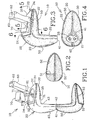
Figure 1 is an exploded side view of an embodiment of an expandable in-ear device according to the present invention; showing the sheath integrally extending out of the core-form, in the unfolded configuration; -
Figure 2 is a bottom view of the embodiment ofFig. 1 ; -
Figure 3 is a side view of the embodiment ofFig. 1 with the sheath folded inside-out over the core-form, in the folded configuration; -
Figure 4 is a bottom view of the embodiment ofFig. 2 ; -
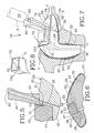
Figure 5 is a partial enlarged section view taken along line 5-5 ofFig. 3 ; showing the handle member secured to the platform section; -
Figure 6 is an enlarged section view taken along line 6-6 ofFig. 3 ; -
Figure 7 is a section view of the embodiment ofFig. 2 inserted in the ear canal and cavum concha of an individual and being expanded by a settable compound material to perfectly assume the same; and -
Figure 8 is a perspective view of another embodiment of the insert member engaging the cavity. - With reference to the annexed drawings the preferred embodiments of the present invention will be herein described for indicative purpose and by no means as of limitation.
- Referring to
Figs. 1 to 8 , there is shown anembodiment 10 of an expandable in-ear device according to the present invention. Thedevice 10 is adapted for being custom fitted in-situ inside the ear canal C and cavum concha V of an individual by injection of a settablecompound material 23 therein. Thedevice 10 includes a core-form 20 defining aplatform section 30 and anipple section 40 and having a core-form shape. Theplatform section 30 that essentially fits into the cavum concha V defines a platformdistal end 32 and a generally opposed platformproximal end 31, the latter defining a platformdistal end periphery 34. Thenipple section 40 that essentially fits into the ear canal C defines a nippledistal end 43 and a generally opposed nippleproximal end 41. Thenipple section 40 integrally extends from the platformproximal end 31 for engaging the ear canal C. A sound bore 21 generally extends from the nippleproximal end 41 to the platformdistal end 32 through both thenipple 40 and theplatform 30 sections, for conducting sound from an environment to inside of the ear canal C. - A
stretchable sheath 50, shown inFig. 1 , is integral to and freely extends away from the nippleproximal end 41 of the core-form 20 in an unfolded configuration of thedevice 10. Thesheath 50 defines a sheath shape that is substantially a mirror image of the shape of the core-form 20. Thesheath 50 is configured and sized so as to substantially assume the core-form shape when folded inside-out over the core-form 20 in a folded configuration of thedevice 10. Thesheath 50 further defines a sheath-to-core-form in-betweenregion 22 when in the folded configuration, as shown inFig. 3 . Thesheath 50 has asheath aperture 51 generally assuming the platformdistal end periphery 34. - The
platform section 30 allows for thesettable compound material 23 to be injected therethrough to reach the in-betweenregion 22 and stretch thesheath 50 away from the core-form 20 so as to expand thedevice 10 fitted in the ear canal C such that it perfectly assume and occlude the latter and the cavum concha V, thereby forming a unitary piece with thedevice 10 after thesettable compound material 23 is fully set. For obvious reasons to one skilled in the art, the in-betweenregion 22 does not communicate with the sound bore 21. - The in-
ear device 10 also preferably includes ahandle member 60 secured, preferably glued, to the platformdistal end 32. Thedevice 10 includes a handle positioning means for positioning thehandle 60 relative to theplatform section 30. In order to properly position thehandle 60 relative to the core-form 20, thehandle 60 preferably has anotch 61 for engaging acorresponding notch recess 33 on theplatform section 30, thenotch 61 and thenotch recess 33 forming the handle positioning means, as shown inFig. 5 . - To ensure a better flow of the
settable compound material 23 inside the in-betweenregion 22 of thedevice 10, the platformproximal end 31 includes a preferablysemi-circular recess 35, adjacent thenipple section 40, as illustrated inFig. 1 . To allow for thecompound material 23 to reach the in-betweenregion 22 via thesemi-circular recess 35 from thedistal end 32 of theplatform 30, a communicatinginjection slit channel 36 substantially extends through theplatform section 30, between the platformdistal end 32 and thesemi-circular recess 35 in fluid communication with the in-betweenregion 22. The injection slitchannel 36, preferably rectilinear, is made to releasably receive a needle N of an injection device such as a syringe S containing thesettable compound material 23. Obviously, the injection slitchannel 36 is made using a sharp tool perforating theplatform 30 prior to folding thesheath 50 over the core-form 20, thereby not damaging thesheath 50. - The
handle 60 is generally elongated and preferably defines a longitudinal reach-throughhole 62 to be in-line with the injection slitchannel 36 for alternatively guiding the perforating tool and the needle N of the syringe S (shown in dashed lines inFig. 7 ). - The
hole 62 of thehandle 60 is preferably includes a thin close-off membrane 63 at a proximal end thereof getting in contact with the core-form 20 in order to prevent any back flow of glue within thehole 62 when thehandle 60 is glued onto theplatform 30. Similarly, to prevent any back flow of thesettable compound material 23 just after injection of the same inside the in-betweenregion 22, the injection slitchannel 36 is preferably self closing upon retraction of the needle N therefrom. - As shown in
Fig. 7 , the platformdistal end periphery 34 defines aplatform protruding surface 37 slightly protruding outwardly from the platformdistal end 32 and defining a protruding surface perimeter. Accordingly, thesheath aperture 51 has a shape to assume the surface perimeter of theplatform protruding surface 37. Preferably, thesheath aperture 51 has its perimeter reinforced with abulge 52 integral therewith for tightly engaging a correspondinggroove 38 on the perimeter of theplatform protruding surface 37. Thesheath aperture bulge 52 is preferably bonded (or glued) into thegroove 38 of theplatform protruding surface 37 to essentially close off the in-betweenregion 22. Thedistal end 21d of the sound bore 21 is located within theplatform protruding surface 37 and is preferably terminated by aslit membrane 24 temporarily closing off the same whenever not releasably inserted therethrough by a remote instrument (not shown) such as a microphone of a measurement apparatus or the like. - Also illustrated in
Figs. 2 and6 , the platformdistal end 32 preferably defines a generally convex shape with a generally elongatedapex 26 and, is substantially symmetrical about the apex 26. The convex shape defines two substantiallyplanar surfaces 25 with the apex 26 defining a common distal edge therebetween. Bothplanar surfaces 25 generally extend downwardly and away from each other from the commondistal edge 26 and towards the platformproximal end 31 in a proximal direction. Only one of the twosurfaces 25 includes the platformdistal end periphery 34 defining theplatform protruding surface 37 while the other one is fully covered by thesheath 50 in the folded configuration of the in-ear device 10 as to form part of the in-betweenregion 22 that is custom fitted in-situ of a cavum concha V of the individual to perfectly assume the same. Obviously thesheath aperture 51 is located on the same sidle as the corresponding protrudingsurface 37. This slope of the convex shape forming thesurfaces 25 enables thedevice 10 to be side specific, either a left or right-handside device and have only thehandle 60 secured to the protrudingsurface 37 protruding out of the ear of the individual. - Furthermore, because of the generally conical aspect of the
nipple section 40 required for its insertion into the ear canal C, thedevice 10 needs a retaining member to prevent it from slidably coming out of the ear canal C. Accordingly, the side of theplatform 30 with thesurface 25 entirely covered by thesheath 50 is configured and sized to sit into the cavum concha V of the ear and provide the required retention. - After the
handle 60 has been installed and the injection slitchannel 36 has been made, thesheath 50 is progressively folded inside-out over the core-form 20. Preferably, thesheath 50 tightly assumes the core-form 20 such that the in-betweenregion 22 is substantially fluidless, with no air entrapped therein. For safety, after folding of thesheath 50, itsaperture 51 is bonded all around the protrudingsurface 37, then the in-betweenregion 22 is typically vacuumed to remove air entrapped therein. At this time, thedevice 10 is ready to be inserted into the ear canal C and have thesettable compound material 23 injected into the in-betweenregion 22 for the in-situ custom fitting of the in-ear device 10, as shown inFig. 7 . Thesheath 50 is then stretched away from the core-form 20 to perfectly assume and occlude the ear canal C. Similarly, the retaining member area of thedevice 10 also have a simultaneous expansion of its part of the in-betweenregion 22 being filled by the settable compound material so as to perfectly assume the shape of the cavum concha V of the individual. Thedevice 10 is then removed from the ear canal C after thecompound material 23 is completely set. - The core-
form 20 is generally solid and rigid enough with substantial inherent structural rigidity while thestretchable sheath 50 is a thin material with substantially no inherent structural rigidity, both of them being preferably a single molded piece made out of a silicone type of material or the like with a hardness value of preferably less than thirty (30) shore-A. Accordingly, as shown inFig. 1 , core-form protrusions 42 at the nippleproximal end 41 are present preferably only for molding purposes of the sound bores 21, 28. They are preferably simply chopped off after folding over of thesheath 50; as shown inFigs. 3 and 4 . Thesettable compound material 23 is preferably a rubber-like type material once it is fully cured with a hardness value of preferably less than thirty (30) shore-A. - Additionally, the
platform section 30 of the in-ear device 10 preferably defines acavity 27 for removably, tightly and at least partially house aninsert member 70 therein considering the fact that the core-form 20 material is substantially resilient. Thecavity 27 substantially extends inwardly from the protrudingsurface 37. The core-form 20 further defines a second sound bore 28 generally extending from the nippleproximal end 41 to thecavity 27 of theplatform 30 through both of thenipple 40 andplatform 30 sections for conducting sound from thecavity 27 to inside of the ear canal C such that theinsert member 70 can be in sound communication with inside of the ear canal C. The second sound bore 28 runs generally parallel to thefirst one 21 except in the region adjacent the platformdistal end 32 where they slightly diverge from each other. - The cavity preferably includes an insert retaining means for releasably retaining the
insert 70 therein. The insert retaining means is preferably formed by the lower section of thehandle 60 defining a step to be releasably engaged by acomplementary locking step 71 of theinsert 70. - Both the
handle 60 and theinsert 70 are preferably made out of silicone type material or the like having a hardness value typically varying between fifty (50) and eighty (80) shore-A. - As shown in
Figs. 1 to 7 , theinsert member 70 can be a plug member to simply close off the second sound bore 28, whereby the in-ear device 10 is a typical earplug device. - Optionally, the
insert member 70 includes acommunication element 72 for communicating with the second sound bore 28. Accordingly, thecommunication element 72 can be a band-pass filter, preferably in the form of an adequately sized extension of the second sound bore 28, for allowing an acceptable frequency range to reach inside the ear canal C, whereby the in-ear device 10 is a typical filtered earplug device. - Also, as shown in
Fig. 8 , thecommunication element 72 of theinsert 70a can be aninsert cavity 73 adapted to be releasably engaged by an electronic circuit (not shown and well known in the art) or the like for amplifying sound within a pre-determined frequency range from the environment to the second sound bore 28, whereby the in-ear device 10 is a typical hearing aid device, more commonly known as an in-the-ear (ITE) hearing aid. Similarly, thecommunication element 72 could be a simple sound bore extension (not shown) adapted to be engaged by an external hearing aid device, such as a commonly known behind-the-ear (BTE) hearing aid or the like, at a distal end thereof and communicating with the second sound bore 28 at a proximal end thereof, whereby the in-ear device 10 is a typical hearing aid adaptable device. - Alternatively, either the
communication element 72 or simply theinsert member 70 could be a simple audio output connector, being wireless or not, from a typical electronic device such as a computer, a laptop-type computer, a cellular-type (or GSM - Global System for Mobile communications) phone, a hand-held-type (or palm) computer or the like that is adapted to releasably fit within theinsert cavity 73. - To prevent an individual from loosing his/her in-
ear devices 10 of the present invention when a pair of them are worn, eachhole 62 of bothhandles 60 can be releasably engaged by a respective resilient plug member (not shown) secured to a respective end of a cord or the like, thereby securing bothdevices 10 together. - Although the present expandable in-ear device has been described with a certain degree of particularity it is to be understood that the disclosure has been made by way of example only and that the present invention is not limited to the features of the embodiments described and illustrated herein, but includes all variations and modifications within the scope of the invention as hereinafter claimed.
Claims (20)
- An expandable in-ear device (10) for being custom fitted in-situ of an ear canal (C) of an individual by injection of a settable compound material (23) therein, said device comprising:- a core-form (20) defining a platform section (30) and a nipple section (40) and having a core-form shape, said platform section (30) defining a platform proximal end (31) and a generally opposed platform distal end (32), said platform distal end (32) defining a platform distal end periphery (34), said nipple section (40) defining a nipple proximal end (41) and a generally opposed nipple distal end (43), said nipple section (40) integrally extends from said platform proximal end (31) for engaging said ear canal (C), said core-form (20) further defines a sound bore (21) generally extending from said nipple proximal end (41) to said platform distal end (32) through both said nipple (40) and platform (30) sections for conducting sound from an environment surrounding said individual to inside of said ear canal (C);- a stretchable sheath (50) being integral to and freely extending away from said nipple proximal end (41) of said core-form (20) adjacent said sound bore (21) in an unfolded configuration of said device (10), said sheath (50) defining a sheath shape being substantially a mirror image of said core-form shape, said sheath (50) being configured and sized so as to substantially assume said core-form shape when folded inside-out over said core-form (20) in a folded configuration of said device (10), said sheath (50) further defining a sheath-to-core-form in-between region (22) when in said folded configuration, said sheath (50) having a sheath aperture (51) generally assuming said platform distal end periphery (34) when in said folded configuration;- said platform section (30) allowing for said settable compound material (23) to be injected therethrough to reach said in-between region (22), thereby expanding said device (10) fitted inside said ear canal (C) by stretching said sheath (50) away from said core-form to perfectly assume and occlude said ear canal (C).
- The device (10) of claim 1, wherein said platform distal end periphery (34) defining a platform protruding surface (37), said platform protruding surface (37) protruding outwardly from said platform distal end (32) and defining a protruding surface perimeter, said sheath aperture (51) having a shape to assume said surface perimeter.
- The device (10) of claim 1, wherein said sheath (50) being a thin and stretchable polymer material with substantially no inherent structural rigidity.
- The device (10) of claim 3, wherein said core-form (20) being generally solid with a material hardness value of less than thirty (30) shore-A.
- The device (10) of claim 1, wherein said sheath (50) tightly assumes said core-form (20) when in said folded configuration as to have said in-between region (22) being substantially fluidless.
- The device (10) of claim 1, wherein said in-ear device (10) being made out of a single molded piece.
- The device (10) of claim 2, wherein said protruding surface perimeter defining a perimeter groove (38) extending therealong, said sheath aperture (51) defining an aperture perimeter, said aperture perimeter being reinforced with a integral bulge (52) tightly engaging said perimeter groove (38) when in said folded configuration so as to substantially close off said in-between region (22).
- The device (10) of claim 1, wherein said sound bore (21) being a first sound bore, said platform section (30) defining a cavity (27) substantially extending inwardly therein from said protruding surface (37), whereby said cavity (27) is for removably, tightly and at least partially house an insert member (70) therein, said core-form (20) further defining a second sound bore (28) generally extending from said nipple proximal end (41) to said cavity (27) through both of said nipple (40) and platform (30) sections for conducting sound from said cavity (27) to inside of said ear canal (C), whereby said insert member (70) is in sound communication with inside of said ear canal (C) via said second sound bore (28).
- The device (10) of claim 8, wherein said cavity (27) includes an insert retaining means for releasably retaining said insert member (70) therein.
- The device (10) of claim 1, wherein said platform distal end (32) includes a slit membrane (24) temporarily closing off said sound bore (21), said slit membrane (24) allows for a remote instrument to be releasably inserted therethrough to get in communication with said sound bore (21).
- The device (10) of claim 1, including a handle member (60) secured to said platform section (30) adjacent said platform distal end (32) for handling said in-ear device (10).
- The device (10) of claim 11, including a handle positioning means for positioning said handle member (60) relative to said platform section (30).
- The device (10) of claim 12, wherein said handle member (60) includes a notch (61) to engage a corresponding notch recess (33) on said platform section (30), said notch (61) and said notch recess (33) forming said handle positioning means.
- The device (10) of claim 8, including a handle member (60) secured to said platform section (30) adjacent said platform distal end (32) for handling said in-ear device (10).
- The device (10) of claim 14, wherein said platform section (30) includes an injection slit channel (36) substantially extending therethrough between said platform distal end (32) to said in-between region (22) to be in fluid communication therewith, said injection slit channel (36) for releasably receiving part of an injection device (N) therein to inject said settable compound material (23) therethrough into said in-between region (22).
- The device (10) of claim 15, wherein said injection slit channel (36) being generally rectilinear, said handle member (60) being generally elongated and defines a longitudinal reach-through hole (62) being substantially in-line with said injection slit channel (36) of said platform section (30), said reach-through hole (62) for guiding an injection device (N) containing said settable compound material (23) into said injection slit channel (36) within said platform section (30).
- The device (10) of claim 16, wherein said reach-through hole (62) of said handle member (60) includes a close-off membrane (63) at one end thereof, said close-off membrane (63) being in contact with said platform section (30) of said core-form (20).
- The device (10) of claim 16, wherein said injection slit channel (36) self closes upon retraction of said injection device (N) therefrom.
- The device (10) of claim 1, wherein said platform distal end (32) defining a generally convex shape, said convex shape has a generally elongated apex (26) and is substantially symmetrical thereabout, said convex shape defining two substantially planar surfaces (25) with said elongated apex (26) defining a common distal edge therebetween, said planar surfaces (25) generally extending away from each other from said common distal edge and towards said platform proximal end (31).
- The device (10) of claim 19, wherein one of said two surfaces (25) includes said platform distal end periphery (34) defining a platform protruding surface (37), said platform protruding surface (37) protruding outwardly from said platform distal end (32) and defining a protruding surface perimeter, said sheath aperture (51) having a shape to assume said surface perimeter, the other of said two surfaces (25) being fully covered by said sheath (50) when in said folded configuration to form part of said in-between region (22) for being custom fitted in-situ of a cavum concha (V) of said individual corresponding to said ear canal (C) so as to perfectly assume said cavum concha (V).
Applications Claiming Priority (3)
| Application Number | Priority Date | Filing Date | Title |
|---|---|---|---|
| US09/785,278 US20020114479A1 (en) | 2001-02-20 | 2001-02-20 | Expandable in-ear device |
| US785278 | 2001-02-20 | ||
| PCT/CA2002/000220 WO2002067626A2 (en) | 2001-02-20 | 2002-02-19 | Expandable in-ear device |
Publications (2)
| Publication Number | Publication Date |
|---|---|
| EP1378146A2 EP1378146A2 (en) | 2004-01-07 |
| EP1378146B1 true EP1378146B1 (en) | 2013-05-29 |
Family
ID=25134969
Family Applications (1)
| Application Number | Title | Priority Date | Filing Date |
|---|---|---|---|
| EP02701132.9A Expired - Lifetime EP1378146B1 (en) | 2001-02-20 | 2002-02-19 | Expandable in-ear device |
Country Status (11)
| Country | Link |
|---|---|
| US (2) | US20020114479A1 (en) |
| EP (1) | EP1378146B1 (en) |
| JP (1) | JP4125127B2 (en) |
| CN (1) | CN100379317C (en) |
| AU (1) | AU2002234463B2 (en) |
| CA (1) | CA2470238C (en) |
| ES (1) | ES2426336T3 (en) |
| HK (1) | HK1070532A1 (en) |
| MX (1) | MXPA03007435A (en) |
| WO (1) | WO2002067626A2 (en) |
| ZA (1) | ZA200306436B (en) |
Families Citing this family (49)
| Publication number | Priority date | Publication date | Assignee | Title |
|---|---|---|---|---|
| DE29918139U1 (en) * | 1999-10-14 | 2000-05-25 | Hörgeräte Seifert GmbH, 81377 München | Otoplasty for behind-the-ear (BTE) hearing aids |
| US7580537B2 (en) * | 1998-11-25 | 2009-08-25 | Insound Medical, Inc. | Sealing retainer for extended wear hearing devices |
| US7664282B2 (en) * | 1998-11-25 | 2010-02-16 | Insound Medical, Inc. | Sealing retainer for extended wear hearing devices |
| US20060291683A1 (en) * | 1998-11-25 | 2006-12-28 | Insound Medical, Inc. | Sealing retainer for extended wear hearing devices |
| US20030051277P1 (en) * | 2001-09-07 | 2003-03-13 | Meilland Alain A. | Floribunda rose plant named 'Meizebul' |
| US7227968B2 (en) * | 2001-06-25 | 2007-06-05 | Sonion Roskilde A/S | Expandsible Receiver Module |
| ATE394020T1 (en) * | 2002-12-23 | 2008-05-15 | Sonion Roskilde As | ENCAPSULATED HANDSET WITH AN EXPANDABLE MEANS SUCH AS A BALLOON |
| US7418105B2 (en) * | 2003-12-05 | 2008-08-26 | Sonomax Hearing Healthcare Inc. | Sheath for in-ear device |
| US7551747B2 (en) * | 2004-02-13 | 2009-06-23 | Insound Medical, Inc. | Perforated cap for a hearing aid |
| DE602004019519D1 (en) | 2004-08-25 | 2009-04-02 | Phonak Ag | Earplugs, methods of making the same and their use |
| US7185734B2 (en) * | 2004-08-25 | 2007-03-06 | Phonak Ag | Hearing protection earplug, use of such an earplug and method for manufacturing such an earplug |
| US7240765B2 (en) * | 2004-08-25 | 2007-07-10 | Phonak Ag | Customized hearing protection earplug with an acoustic filter and method for manufacturing the same |
| US7369670B2 (en) * | 2004-08-25 | 2008-05-06 | Phonak Ag | Earplug and method for manufacturing the same |
| US7864972B2 (en) * | 2004-10-14 | 2011-01-04 | Sonomax Hearing Healthcare Inc. | Customized in-ear interface for acoustic equipment and method |
| US7401680B2 (en) * | 2004-12-23 | 2008-07-22 | Phonak Ag | Hearing protection earplug and use of the same |
| US7715572B2 (en) * | 2005-02-04 | 2010-05-11 | Solomito Jr Joe A | Custom-fit hearing device kit and method of use |
| US20120057740A1 (en) * | 2006-03-15 | 2012-03-08 | Mark Bryan Rosal | Security and protection device for an ear-mounted audio amplifier or telecommunication instrument |
| US20070217641A1 (en) * | 2006-03-15 | 2007-09-20 | Rosal Mark B | Ear Gear |
| US8550344B2 (en) * | 2006-06-16 | 2013-10-08 | The Invention Science Fund I, Llc | Specialty stents with flow control features or the like |
| US8163003B2 (en) * | 2006-06-16 | 2012-04-24 | The Invention Science Fund I, Llc | Active blood vessel sleeve methods and systems |
| US20080133040A1 (en) * | 2006-06-16 | 2008-06-05 | Searete Llc, A Limited Liability Corporation Of The State Of Delaware | Methods and systems for specifying a blood vessel sleeve |
| US8147537B2 (en) * | 2006-06-16 | 2012-04-03 | The Invention Science Fund I, Llc | Rapid-prototyped custom-fitted blood vessel sleeve |
| US8095382B2 (en) * | 2006-06-16 | 2012-01-10 | The Invention Science Fund I, Llc | Methods and systems for specifying a blood vessel sleeve |
| US8478437B2 (en) * | 2006-06-16 | 2013-07-02 | The Invention Science Fund I, Llc | Methods and systems for making a blood vessel sleeve |
| US8551155B2 (en) * | 2006-06-16 | 2013-10-08 | The Invention Science Fund I, Llc | Stent customization system and method |
| US7818084B2 (en) * | 2006-06-16 | 2010-10-19 | The Invention Science Fund, I, LLC | Methods and systems for making a blood vessel sleeve |
| US7506720B1 (en) * | 2006-07-21 | 2009-03-24 | Hicks Tammera D | Animal ear protection apparatus |
| WO2008070986A1 (en) * | 2006-12-11 | 2008-06-19 | Sonomax Hearing Healthcare Inc. | Method for customizing an in-ear device |
| US8391534B2 (en) | 2008-07-23 | 2013-03-05 | Asius Technologies, Llc | Inflatable ear device |
| US8229128B2 (en) * | 2008-02-20 | 2012-07-24 | Personics Holdings Inc. | Device for acoustic sealing |
| CA2776905A1 (en) * | 2009-10-05 | 2011-04-14 | Sonomax Technologies Inc. | Pressure regulation mechanism for inflatable in-ear device |
| AU2010305286B2 (en) * | 2009-10-05 | 2014-03-06 | Sonomax Technologies Inc. | Settable compound delivery device and system for inflatable in-ear device |
| US11000415B2 (en) | 2009-10-05 | 2021-05-11 | Eers Global Technologies Inc. | Sealing assembly for inflatable in-ear device |
| US8422719B2 (en) * | 2009-10-05 | 2013-04-16 | Sonomax Technologies Inc. | Miniaturized receiver assembly for in-ear noise-isolating earphones |
| US20110079228A1 (en) * | 2009-10-05 | 2011-04-07 | Michael Maloney | Sealing assembly for inflatable in-ear device |
| EP2494791A1 (en) * | 2009-10-30 | 2012-09-05 | VIBRANT Med-El Hearing Technology GmbH | Implantable signal delivery systems |
| CA2785573A1 (en) | 2009-12-24 | 2011-06-30 | Sonomax Technologies Inc. | Quasi-triangular in-ear device |
| CA2785579A1 (en) | 2009-12-24 | 2011-06-30 | Sonomax Technologies Inc. | In-ear device with selectable frequency response |
| CN103039089A (en) * | 2009-12-31 | 2013-04-10 | 索纳麦克斯科技股份有限公司 | Head-mounted device for settable compound delivery system for inflatable in-ear device |
| US8526651B2 (en) * | 2010-01-25 | 2013-09-03 | Sonion Nederland Bv | Receiver module for inflating a membrane in an ear device |
| CA2819906A1 (en) | 2010-12-01 | 2012-06-07 | Sonomax Technologies Inc. | Advanced communication earpiece device and method |
| US8965030B2 (en) | 2011-03-15 | 2015-02-24 | Apple Inc. | Seamless earbud structures and methods for making the same |
| US8577693B2 (en) | 2011-07-13 | 2013-11-05 | The Invention Science Fund I, Llc | Specialty stents with flow control features or the like |
| US8682016B2 (en) | 2011-11-23 | 2014-03-25 | Insound Medical, Inc. | Canal hearing devices and batteries for use with same |
| US8761423B2 (en) | 2011-11-23 | 2014-06-24 | Insound Medical, Inc. | Canal hearing devices and batteries for use with same |
| US9002023B2 (en) | 2012-04-17 | 2015-04-07 | Bose Corporation | In-ear audio device customization |
| US9398384B2 (en) * | 2013-12-11 | 2016-07-19 | Cochlear Limited | Hearing prosthesis accessory |
| US10034105B2 (en) * | 2016-01-04 | 2018-07-24 | Starkey Laboratories, Inc. | Article with internal light source for fitting in-situ and related devices and methods |
| EP3694226A1 (en) | 2019-02-08 | 2020-08-12 | José Collado Bonet | Flexible adaptive hearing aid |
Family Cites Families (12)
| Publication number | Priority date | Publication date | Assignee | Title |
|---|---|---|---|---|
| US2719523A (en) | 1954-05-25 | 1955-10-04 | Gierke Henning E Von | Ear protector |
| US3906170A (en) * | 1973-12-10 | 1975-09-16 | Daniel W Guice | Protective cover |
| JPS5330316A (en) | 1976-09-01 | 1978-03-22 | Koken Kk | Sealed sound receiver |
| US4712245A (en) | 1985-01-24 | 1987-12-08 | Oticon Electronics A/S | In-the-ear hearing aid with the outer wall formed by rupturing a two-component chamber |
| DE3715082A1 (en) * | 1987-05-06 | 1988-11-17 | Siemens Ag | METHOD AND DEVICE FOR PRODUCING AN OTOPLASTIC |
| DE8816266U1 (en) * | 1988-01-19 | 1989-04-13 | Siemens AG, 1000 Berlin und 8000 München | Ear inserts for hearing aids, in particular earmolds for in-the-ear hearing aids and earmolds for behind-the-ear hearing aids |
| US5131411A (en) | 1990-08-20 | 1992-07-21 | Virginia Polytechnic Institute & State University | Custom-fitting earplug formed in situ using foaming action |
| US5333622A (en) * | 1990-08-20 | 1994-08-02 | The Center For Innovative Technology | Earplug and hearing devices formed in-situ |
| US5249234A (en) * | 1991-10-11 | 1993-09-28 | Butler Michael J | Cover for behind-the-ear type hearing aids and methods of making and using the same |
| WO1997036456A1 (en) | 1996-03-26 | 1997-10-02 | Sarnoff Corporation | Battery and circuitry assembly |
| US6359993B2 (en) | 1999-01-15 | 2002-03-19 | Sonic Innovations | Conformal tip for a hearing aid with integrated vent and retrieval cord |
| GB9907050D0 (en) | 1999-03-26 | 1999-05-19 | Sonomax Sft Inc | System for fitting a hearing device in the ear |
-
2001
- 2001-02-20 US US09/785,278 patent/US20020114479A1/en not_active Abandoned
-
2002
- 2002-02-19 MX MXPA03007435A patent/MXPA03007435A/en active IP Right Grant
- 2002-02-19 CN CNB028052579A patent/CN100379317C/en not_active Expired - Fee Related
- 2002-02-19 WO PCT/CA2002/000220 patent/WO2002067626A2/en active Application Filing
- 2002-02-19 JP JP2002567011A patent/JP4125127B2/en not_active Expired - Fee Related
- 2002-02-19 CA CA2470238A patent/CA2470238C/en not_active Expired - Lifetime
- 2002-02-19 ES ES02701132T patent/ES2426336T3/en not_active Expired - Lifetime
- 2002-02-19 EP EP02701132.9A patent/EP1378146B1/en not_active Expired - Lifetime
- 2002-02-19 AU AU2002234463A patent/AU2002234463B2/en not_active Ceased
-
2003
- 2003-01-01 ZA ZA200306436A patent/ZA200306436B/en unknown
- 2003-01-21 US US10/349,545 patent/US6754357B2/en not_active Expired - Lifetime
-
2005
- 2005-04-12 HK HK05103077A patent/HK1070532A1/en not_active IP Right Cessation
Also Published As
| Publication number | Publication date |
|---|---|
| MXPA03007435A (en) | 2003-11-18 |
| US20030112990A1 (en) | 2003-06-19 |
| JP2004520748A (en) | 2004-07-08 |
| ZA200306436B (en) | 2004-08-27 |
| JP4125127B2 (en) | 2008-07-30 |
| ES2426336T3 (en) | 2013-10-22 |
| CA2470238A1 (en) | 2002-08-29 |
| AU2002234463B2 (en) | 2007-02-15 |
| CA2470238C (en) | 2011-02-08 |
| US20020114479A1 (en) | 2002-08-22 |
| CN100379317C (en) | 2008-04-02 |
| EP1378146A2 (en) | 2004-01-07 |
| CN1537401A (en) | 2004-10-13 |
| HK1070532A1 (en) | 2005-06-17 |
| WO2002067626A3 (en) | 2003-10-02 |
| WO2002067626A2 (en) | 2002-08-29 |
| US6754357B2 (en) | 2004-06-22 |
Similar Documents
| Publication | Publication Date | Title |
|---|---|---|
| EP1378146B1 (en) | Expandable in-ear device | |
| AU2002234463A1 (en) | Expandable in-ear device | |
| US6724902B1 (en) | Canal hearing device with tubular insert | |
| JP4778052B2 (en) | Hearing aids and earpieces for hearing aids | |
| US8538055B2 (en) | Semi-permanent canal hearing device and insertion method | |
| US5979589A (en) | Flexible hearing aid | |
| US7421086B2 (en) | Hearing aid system | |
| JP4619410B2 (en) | Hearing aid earpiece and hearing aid | |
| CN110679160B (en) | Ear piece and earplug and hearing aid applying same | |
| US8391526B2 (en) | Ear device for improved fit and sound | |
| WO2001024578A9 (en) | Retention and extraction device for a hearing aid | |
| EP1535489A1 (en) | Canal hearing device with tubular insert | |
| JPS62151100A (en) | Hearing aid | |
| US8989418B2 (en) | Ear device for improved fit and sound | |
| JP2000166959A (en) | Bone conductive speaker | |
| US7418105B2 (en) | Sheath for in-ear device | |
| JPH1098797A (en) | Hearing aid |
Legal Events
| Date | Code | Title | Description |
|---|---|---|---|
| PUAI | Public reference made under article 153(3) epc to a published international application that has entered the european phase |
Free format text: ORIGINAL CODE: 0009012 |
|
| 17P | Request for examination filed |
Effective date: 20030918 |
|
| AK | Designated contracting states |
Kind code of ref document: A2 Designated state(s): AT BE CH CY DE DK ES FI FR GB GR IE IT LI LU MC NL PT SE TR |
|
| AX | Request for extension of the european patent |
Extension state: AL LT LV MK RO SI |
|
| RAP1 | Party data changed (applicant data changed or rights of an application transferred) |
Owner name: SONOMAX HEARING HEALTHCARE, INC |
|
| GRAP | Despatch of communication of intention to grant a patent |
Free format text: ORIGINAL CODE: EPIDOSNIGR1 |
|
| GRAS | Grant fee paid |
Free format text: ORIGINAL CODE: EPIDOSNIGR3 |
|
| GRAA | (expected) grant |
Free format text: ORIGINAL CODE: 0009210 |
|
| AK | Designated contracting states |
Kind code of ref document: B1 Designated state(s): AT BE CH CY DE DK ES FI FR GB GR IE IT LI LU MC NL PT SE TR |
|
| REG | Reference to a national code |
Ref country code: GB Ref legal event code: FG4D |
|
| REG | Reference to a national code |
Ref country code: CH Ref legal event code: EP |
|
| REG | Reference to a national code |
Ref country code: AT Ref legal event code: REF Ref document number: 615032 Country of ref document: AT Kind code of ref document: T Effective date: 20130615 |
|
| REG | Reference to a national code |
Ref country code: IE Ref legal event code: FG4D |
|
| REG | Reference to a national code |
Ref country code: DE Ref legal event code: R096 Ref document number: 60245031 Country of ref document: DE Effective date: 20130725 |
|
| REG | Reference to a national code |
Ref country code: SE Ref legal event code: TRGR |
|
| REG | Reference to a national code |
Ref country code: NL Ref legal event code: T3 |
|
| REG | Reference to a national code |
Ref country code: AT Ref legal event code: MK05 Ref document number: 615032 Country of ref document: AT Kind code of ref document: T Effective date: 20130529 |
|
| REG | Reference to a national code |
Ref country code: ES Ref legal event code: FG2A Ref document number: 2426336 Country of ref document: ES Kind code of ref document: T3 Effective date: 20131022 |
|
| PG25 | Lapsed in a contracting state [announced via postgrant information from national office to epo] |
Ref country code: AT Free format text: LAPSE BECAUSE OF FAILURE TO SUBMIT A TRANSLATION OF THE DESCRIPTION OR TO PAY THE FEE WITHIN THE PRESCRIBED TIME-LIMIT Effective date: 20130529 Ref country code: GR Free format text: LAPSE BECAUSE OF FAILURE TO SUBMIT A TRANSLATION OF THE DESCRIPTION OR TO PAY THE FEE WITHIN THE PRESCRIBED TIME-LIMIT Effective date: 20130830 Ref country code: PT Free format text: LAPSE BECAUSE OF FAILURE TO SUBMIT A TRANSLATION OF THE DESCRIPTION OR TO PAY THE FEE WITHIN THE PRESCRIBED TIME-LIMIT Effective date: 20130930 Ref country code: FI Free format text: LAPSE BECAUSE OF FAILURE TO SUBMIT A TRANSLATION OF THE DESCRIPTION OR TO PAY THE FEE WITHIN THE PRESCRIBED TIME-LIMIT Effective date: 20130529 |
|
| PG25 | Lapsed in a contracting state [announced via postgrant information from national office to epo] |
Ref country code: DK Free format text: LAPSE BECAUSE OF FAILURE TO SUBMIT A TRANSLATION OF THE DESCRIPTION OR TO PAY THE FEE WITHIN THE PRESCRIBED TIME-LIMIT Effective date: 20130529 Ref country code: BE Free format text: LAPSE BECAUSE OF FAILURE TO SUBMIT A TRANSLATION OF THE DESCRIPTION OR TO PAY THE FEE WITHIN THE PRESCRIBED TIME-LIMIT Effective date: 20130529 |
|
| PLBE | No opposition filed within time limit |
Free format text: ORIGINAL CODE: 0009261 |
|
| STAA | Information on the status of an ep patent application or granted ep patent |
Free format text: STATUS: NO OPPOSITION FILED WITHIN TIME LIMIT |
|
| 26N | No opposition filed |
Effective date: 20140303 |
|
| REG | Reference to a national code |
Ref country code: DE Ref legal event code: R097 Ref document number: 60245031 Country of ref document: DE Effective date: 20140303 |
|
| PG25 | Lapsed in a contracting state [announced via postgrant information from national office to epo] |
Ref country code: LU Free format text: LAPSE BECAUSE OF FAILURE TO SUBMIT A TRANSLATION OF THE DESCRIPTION OR TO PAY THE FEE WITHIN THE PRESCRIBED TIME-LIMIT Effective date: 20140219 Ref country code: MC Free format text: LAPSE BECAUSE OF FAILURE TO SUBMIT A TRANSLATION OF THE DESCRIPTION OR TO PAY THE FEE WITHIN THE PRESCRIBED TIME-LIMIT Effective date: 20130529 |
|
| REG | Reference to a national code |
Ref country code: CH Ref legal event code: PL |
|
| PG25 | Lapsed in a contracting state [announced via postgrant information from national office to epo] |
Ref country code: CH Free format text: LAPSE BECAUSE OF NON-PAYMENT OF DUE FEES Effective date: 20140228 Ref country code: LI Free format text: LAPSE BECAUSE OF NON-PAYMENT OF DUE FEES Effective date: 20140228 |
|
| REG | Reference to a national code |
Ref country code: IE Ref legal event code: MM4A |
|
| PG25 | Lapsed in a contracting state [announced via postgrant information from national office to epo] |
Ref country code: IE Free format text: LAPSE BECAUSE OF NON-PAYMENT OF DUE FEES Effective date: 20140219 |
|
| REG | Reference to a national code |
Ref country code: FR Ref legal event code: PLFP Year of fee payment: 14 |
|
| PGFP | Annual fee paid to national office [announced via postgrant information from national office to epo] |
Ref country code: ES Payment date: 20150212 Year of fee payment: 14 Ref country code: IT Payment date: 20150216 Year of fee payment: 14 |
|
| PGFP | Annual fee paid to national office [announced via postgrant information from national office to epo] |
Ref country code: SE Payment date: 20150227 Year of fee payment: 14 |
|
| REG | Reference to a national code |
Ref country code: FR Ref legal event code: PLFP Year of fee payment: 15 |
|
| PG25 | Lapsed in a contracting state [announced via postgrant information from national office to epo] |
Ref country code: CY Free format text: LAPSE BECAUSE OF FAILURE TO SUBMIT A TRANSLATION OF THE DESCRIPTION OR TO PAY THE FEE WITHIN THE PRESCRIBED TIME-LIMIT Effective date: 20130529 |
|
| PG25 | Lapsed in a contracting state [announced via postgrant information from national office to epo] |
Ref country code: TR Free format text: LAPSE BECAUSE OF FAILURE TO SUBMIT A TRANSLATION OF THE DESCRIPTION OR TO PAY THE FEE WITHIN THE PRESCRIBED TIME-LIMIT Effective date: 20130529 |
|
| REG | Reference to a national code |
Ref country code: SE Ref legal event code: EUG |
|
| PG25 | Lapsed in a contracting state [announced via postgrant information from national office to epo] |
Ref country code: SE Free format text: LAPSE BECAUSE OF NON-PAYMENT OF DUE FEES Effective date: 20160220 |
|
| PG25 | Lapsed in a contracting state [announced via postgrant information from national office to epo] |
Ref country code: IT Free format text: LAPSE BECAUSE OF NON-PAYMENT OF DUE FEES Effective date: 20160219 |
|
| REG | Reference to a national code |
Ref country code: FR Ref legal event code: PLFP Year of fee payment: 16 |
|
| PG25 | Lapsed in a contracting state [announced via postgrant information from national office to epo] |
Ref country code: ES Free format text: LAPSE BECAUSE OF NON-PAYMENT OF DUE FEES Effective date: 20160220 |
|
| PGFP | Annual fee paid to national office [announced via postgrant information from national office to epo] |
Ref country code: NL Payment date: 20170216 Year of fee payment: 16 |
|
| REG | Reference to a national code |
Ref country code: FR Ref legal event code: PLFP Year of fee payment: 17 |
|
| REG | Reference to a national code |
Ref country code: NL Ref legal event code: MM Effective date: 20180301 |
|
| PG25 | Lapsed in a contracting state [announced via postgrant information from national office to epo] |
Ref country code: NL Free format text: LAPSE BECAUSE OF NON-PAYMENT OF DUE FEES Effective date: 20180301 |
|
| PGFP | Annual fee paid to national office [announced via postgrant information from national office to epo] |
Ref country code: GB Payment date: 20190218 Year of fee payment: 18 Ref country code: DE Payment date: 20190219 Year of fee payment: 18 |
|
| PGFP | Annual fee paid to national office [announced via postgrant information from national office to epo] |
Ref country code: FR Payment date: 20190219 Year of fee payment: 18 |
|
| REG | Reference to a national code |
Ref country code: DE Ref legal event code: R119 Ref document number: 60245031 Country of ref document: DE |
|
| GBPC | Gb: european patent ceased through non-payment of renewal fee |
Effective date: 20200219 |
|
| PG25 | Lapsed in a contracting state [announced via postgrant information from national office to epo] |
Ref country code: GB Free format text: LAPSE BECAUSE OF NON-PAYMENT OF DUE FEES Effective date: 20200219 Ref country code: FR Free format text: LAPSE BECAUSE OF NON-PAYMENT OF DUE FEES Effective date: 20200229 Ref country code: DE Free format text: LAPSE BECAUSE OF NON-PAYMENT OF DUE FEES Effective date: 20200901 |