EP1377137A2 - Circuit and procedure for generating a X-ray tube voltage - Google Patents
Circuit and procedure for generating a X-ray tube voltage Download PDFInfo
- Publication number
- EP1377137A2 EP1377137A2 EP03013256A EP03013256A EP1377137A2 EP 1377137 A2 EP1377137 A2 EP 1377137A2 EP 03013256 A EP03013256 A EP 03013256A EP 03013256 A EP03013256 A EP 03013256A EP 1377137 A2 EP1377137 A2 EP 1377137A2
- Authority
- EP
- European Patent Office
- Prior art keywords
- voltage
- manipulated variable
- value
- control device
- ray tube
- Prior art date
- Legal status (The legal status is an assumption and is not a legal conclusion. Google has not performed a legal analysis and makes no representation as to the accuracy of the status listed.)
- Withdrawn
Links
Images

Classifications
-
- H—ELECTRICITY
- H05—ELECTRIC TECHNIQUES NOT OTHERWISE PROVIDED FOR
- H05G—X-RAY TECHNIQUE
- H05G1/00—X-ray apparatus involving X-ray tubes; Circuits therefor
- H05G1/08—Electrical details
- H05G1/26—Measuring, controlling or protecting
- H05G1/30—Controlling
- H05G1/32—Supply voltage of the X-ray apparatus or tube
-
- H—ELECTRICITY
- H05—ELECTRIC TECHNIQUES NOT OTHERWISE PROVIDED FOR
- H05G—X-RAY TECHNIQUE
- H05G1/00—X-ray apparatus involving X-ray tubes; Circuits therefor
- H05G1/08—Electrical details
- H05G1/10—Power supply arrangements for feeding the X-ray tube
- H05G1/20—Power supply arrangements for feeding the X-ray tube with high-frequency ac; with pulse trains
Definitions
- the invention relates to a circuit arrangement for generating an X-ray tube voltage with an inverter circuit for generating a high-frequency AC voltage, with a high-voltage generator for converting the high-frequency AC voltage into a high voltage for the X-ray tube and with a voltage regulating device which is based on the deviation of an actual X-ray tube voltage from a target voltage.
- X-ray tube voltage generates a first manipulated variable value for a manipulated variable for the inverter circuit in order to achieve an adaptation of the actual X-ray tube voltage to the desired X-ray tube voltage.
- Such a circuit arrangement is known from DE 29 43 816 C2.
- the invention relates to an x-ray generator with such a circuit arrangement, an x-ray device with such an x-ray generator and a corresponding method for generating an x-ray tube voltage.
- Modern X-ray generators often have circuit arrangements of the type mentioned at the outset for generating an X-ray tube voltage. Since the mains frequency is first rectified and then converted back into a high-frequency AC voltage, which is finally transformed to the desired voltage, such generators are also referred to as high-frequency generators.
- the voltage regulating device serves to regulate the high voltage on the x-ray tube to the diagnostically required value as optimally as possible and to maintain it there with the required accuracy.
- the circuit arrangement additionally has a measuring circuit for measuring an oscillating current of the high-frequency alternating voltage present at an output of the inverter circuit.
- a second manipulated variable value for the specified manipulated variable for the inverter circuit is then generated on the basis of the deviation of a determined current actual oscillating current value from a predetermined oscillating current maximum value.
- the voltage regulating device and the oscillating current regulating device are then followed by a switching device which compares the first manipulated variable value and the second manipulated variable value and only forwards the respectively smaller manipulated variable value as the resulting manipulated variable value to the inverter circuit.
- the method according to the invention using a vibration current control device, to separately determine a second manipulated variable value on the basis of the deviations of an actual vibration current value from a predetermined maximum oscillation current value and to compare it with the first manipulated variable value of the voltage control device and to supply only the respectively smaller manipulated variable value to the inverter circuit, that, in the normal case, the voltage regulating device regulates very quickly, which is only in the limit cases when a critical range with regard to the oscillating current is reached, is replaced by the oscillating current control device.
- At least one PI controller is used for at least one of the two control devices, particularly preferably for both control devices.
- the integral part of the controller in question has the task of determining the stationary control error. H. to force the control error in the steady state to zero. This reliably avoids a permanent control deviation.
- the control devices preferably consist of successive proportional parts and integral parts. The advantage over a parallel PI controller structure is that the controller parameters regarding gain and reset time can be set separately.
- a PID controller can also be used instead of a PI controller.
- the output of the switching device is connected to an input of the voltage control device and / or the oscillation current control device in order to return the resulting manipulated variable value.
- the voltage regulating device and / or the oscillating current regulating device are designed in such a way that they are carried along with the resulting manipulated variable value when the one generated by the relevant regulating device Manipulated variable value itself is not passed on as the resulting manipulated variable value.
- the respective control device compares the resulting manipulated variable with its own manipulated variable value, which is also traced internally. This variant prevents additional settling processes due to jumps when switching between the two control devices.
- the switching device is preferably designed such that it forwards at least one predetermined minimum manipulated variable value to the inverter circuit as the resulting manipulated variable value.
- a maximum of a predetermined manipulated variable maximum value is preferably also forwarded to the inverter circuit as the resulting manipulated variable value.
- the resulting manipulated variable is actively limited to a range between the minimum value and the maximum value.
- controller parameter a parameter for the set x-ray tube voltage and preferably also for the set x-ray tube current is given to corresponding inputs of the respective control device, as a result of which the parameters of the relevant control devices are set appropriately internally.
- Such a circuit arrangement according to the invention for generating an X-ray tube voltage can in principle be used in any conventional X-ray generator, regardless of how the X-ray generator relates to its other components, such as the various measuring devices or the heating power supply is set up.
- the invention can be used largely independently of the specific design of the inverter circuit and the high-voltage generator.
- FIG. 1a The typical components of an X-ray generator are shown in FIG. 1a, which represent the controlled system with respect to the regulation of the X-ray tube voltage U Rö . These initially include a resonant circuit inverter G si, a high voltage generator G su and an X-ray tube 6.
- the inverter circuit G si has a plurality of power semiconductors 3, which are switched accordingly in such a way that a DC link voltage V z becomes a high-frequency voltage is converted.
- the inverter circuit G si also has a voltage frequency converter 2, which converts a voltage value Y (t) into a drive frequency f a with which the power semiconductors 3 of the inverter G si are driven.
- the input voltage thus forms the manipulated variable Y (t) of the controlled system.
- the G si inverter circuit is a resonant circuit inverter (inverter).
- inverter for example a rectangular inverter or any series or multi-resonance inverter, can also be used.
- the high voltage generator G su consists on the one hand of a transformer 4 with a transmission factor ü and a rectifying and smoothing device 5 connected downstream of the transformer.
- the x-ray tube voltage U Rö present at the output of the rectifying and smoothing device 5 is supplied to the x-ray tube 6.
- FIG. 1b shows a structure diagram for a control loop according to the prior art.
- the inverter circuit G si is shown here as a block and can be described in the control-technical sense by the proportional transmission factor K si and a time constant T si , whereby in particular the proportional transmission factor K si is strongly non-linear due to resonance phenomena in the inverter G si , i.e. from the operating point of the inverter G si depends.
- the high voltage generator G su is also shown as a block. It can be described by the proportional transmission factor K su and the time constant T su , both variables being directly dependent on the X-ray tube voltage U Rö and the X-ray tube current I Rö , ie encompassing a large range of values depending on the operating point .
- i sw (t) is the oscillating current of the inverter G si , which supplies the primary winding of the high-voltage transformer 4 of the high-voltage generator G su . To damage the power semiconductor 3 in of the inverter circuit G si , the oscillating current i sw (t) must not exceed a maximum value.
- the actual voltage V u (t) present there at a specific time t is compared with a desired value W U (t) which corresponds to the desired X-ray tube voltage U Rö , ie the Difference is fed to a voltage control G RU , which is also shown here in the form of a block.
- This voltage control device G RU is conventionally a simple PI controller which, depending on the deviation of the actual value V U (t) from the setpoint W U (t), generates the manipulated variable Y (t), which then responds to the input of the Voltage frequency converter 2 of the inverter circuit G si is given.
- the control speed of the voltage control device G RU must be set so slowly that the oscillating current i sw (t) does not exceed the maximum permissible value even when starting up. This means that rapid regulation with the G RU voltage regulator is not possible, and thus malfunctions can only be regulated slowly.
- the regulator parameters of the voltage regulator G RU must also be adapted accordingly, since the oscillating current i sw (t) is only limited indirectly here.
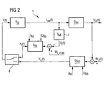
- FIG. 2 clearly shows the change in the structure of the control loop according to the invention.
- the X-ray tube voltage regulating device G RU also forms from the difference between the desired x-ray tube voltage, ie the target voltage W U (t), and the actual x-ray tube voltage, ie the actual x-ray tube voltage V U (t), a manipulated variable Y U (t).
- the oscillating current i sw (t) is measured by means of a smoothing element 7.
- This smoothing element 7 is described in terms of control technology by the additional time constant T MI .
- Both the first manipulated variable value Y U (t), which is formed by the voltage control device G RU , and the second manipulated variable value Y I (t), which is formed by the oscillating current control device G RI , are fed to a switching device 8.
- This switching device 8 selects between the two manipulated variable values Y U (t) and Y I (t) that manipulated variable value Y U (t), Y I (t) that is smaller at the current time t, and routes this manipulated variable value Y U (t ), Y I (t) as the resulting manipulated variable value Y (t) to the inverter circuit G si .
- Both control devices G RI , G RU each contain a PI controller. A permanent control deviation is avoided by the integral part of the PI controller.
- This separation control according to FIG. 2 has the advantage that, in the "normal case", the voltage regulating device G RU is responsible for regulating the x-ray tube voltage. Only in cases in which the current manipulated variable value Y U (t) generated by the voltage regulating device G RU would lead to the oscillating current i sw (t) being a permitted maximum value would exceed, the current manipulated variable value Y I (t) generated by the oscillating current control device G RI is smaller than the manipulated variable value Y U (t) generated by the voltage control device G RU . Therefore, in these cases the voltage regulating device G RU is effectively overridden and only the oscillating current regulating device G RI acts.
- the x-ray tube voltage control itself is not normally slowed down by the measuring time constant T MI of the oscillating current i sw (t) in the structure according to the invention, since the smoothing element 7 is not in the control loop of the x-ray tube voltage.
- the dimensioning of the two control devices G RU , G RI can be made considerably easier if their parameters, ie the controller gains and the reset times, are controlled depending on the working point.
- the two control devices G RI , G RU are each supplied with the values of the set X-ray tube voltage U Rö and the set X-ray tube current I Rö .
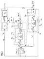
- FIG. 3 shows a more detailed structural diagram of the control loop according to FIG. 2, the control loops here having additional, particularly advantageous features.
- the switching device 8 has further inputs via which the switching device 8 is given a maximum manipulated variable value Y max and a minimum manipulated variable value Y min .
- the switching device 8 is constructed in such a way that at least the manipulated variable minimum value Y min and at most the manipulated variable maximum value Y max are output.
- a manipulated variable range is specified dynamically, within which the manipulated variable Y (t) currently passed on to the inverter circuit G si moves.
- the manipulated variable maximum value Y max and the manipulated variable minimum value Y min are usually set at the factory. In this respect, they can already be specified by appropriate design of the switching device 8 itself.
- FIG. 3 also shows a more precise structure of the voltage regulating device G RU and the oscillating current regulating device G RI .
- These are PI controllers with a proportional component 12, 15 and an integral component 13, 14 connected behind them.
- the proportional components 12, 15 are again determined by the transmission factors K PRI and K PRU and the integral components 13, 14 by the Time constants T NI or T NU .
- the resulting manipulated variable value Y (t) is fed back in this exemplary embodiment by connecting the output 9 of the switching device 8 to additional inputs 10, 11 of the voltage control device G RU or the oscillating current control device G RI .
- the respective manipulated variable value Y U (t), Y I (t) generated by the control device G RU , G RI is also fed back before the integral component 13, 14 and the difference between the feedback, resulting manipulated variable value Y (t) and the respective own manipulated variable value Y U (t), Y I (t) are formed.
- both control devices G RU , G RI each have limit monitors which are coupled such that the integral part 13, 14 of the respectively inactive control device G RU , G RI from the integral part 13, 14 of the active control device - ie the control device G RU , G RI , whose manipulated variable value Y U (t), Y I (t) forms the resulting manipulated variable value Y (t) - is carried along.
- the control devices G RU , G RI would run into the stop, which would result in the integral parts 13, 14 being overloaded. This would in turn lead to a deterioration in the transient response when switching over (wind-up effect).
Abstract
Description
Die Erfindung betrifft eine Schaltungsanordnung zur Erzeugung einer Röntgenröhrenspannung mit einer Wechselrichterschaltung zur Erzeugung einer hochfrequenten Wechselspannung, mit einem Hochspannungserzeuger zur Umwandlung der hochfrequenten Wechselspannung in eine Hochspannung für die Röntgenröhre und mit einer Spannungsregeleinrichtung, die auf Basis der Abweichung einer Ist-Röntgenröhrenspannung von einer Soll-Röntgenröhrenspannung einen ersten Stellgrößenwert für eine Stellgröße für die Wechselrichterschaltung zur Erreichung einer Anpassung der Ist-Röntgenröhrenspannung an die Soll-Röntgenröhrenspannung erzeugt. Eine derartige Schaltungsanordnung ist aus der DE 29 43 816 C2 bekannt.The invention relates to a circuit arrangement for generating an X-ray tube voltage with an inverter circuit for generating a high-frequency AC voltage, with a high-voltage generator for converting the high-frequency AC voltage into a high voltage for the X-ray tube and with a voltage regulating device which is based on the deviation of an actual X-ray tube voltage from a target voltage. X-ray tube voltage generates a first manipulated variable value for a manipulated variable for the inverter circuit in order to achieve an adaptation of the actual X-ray tube voltage to the desired X-ray tube voltage. Such a circuit arrangement is known from DE 29 43 816 C2.
Darüber hinaus betrifft die Erfindung einen Röntgengenerator mit einer derartigen Schaltungsanordnung, eine Röntgeneinrichtung mit einem solchen Röntgengenerator sowie ein entsprechendes Verfahren zur Erzeugung einer Röntgenröhrenspannung.Furthermore, the invention relates to an x-ray generator with such a circuit arrangement, an x-ray device with such an x-ray generator and a corresponding method for generating an x-ray tube voltage.
Moderne Röntgengeneratoren weisen zur Erzeugung einer Röntgenröhrenspannung häufig Schaltungsanordnungen der eingangs genannten Art auf. Da die Netzfrequenz zunächst gleichgerichtet und dann wieder in eine hochfrequente Wechselspannung umgewandelt wird, welche schließlich auf die gewünschte Spannung transformiert wird, werden derartige Generatoren auch als Hochfrequenzgeneratoren bezeichnet. Die Spannungsregeleinrichtung dient hierbei dazu, die Hochspannung an der Röntgenröhre möglichst zeitoptimal auf den diagnostisch erforderlichen Wert zu regeln und dort mit der erforderlichen Genauigkeit zu halten. Gegenüber konventionellen Generatoren, bei denen die Hochspannung mit der vorliegenden Netzfrequenz zunächst transformiert, dann gleichgerichtet und schließlich der Röntgenröhre zugeführt wird, hat eine solche Schaltungsanordnung den Vorteil, dass sie im Prinzip durch einen relativ schnellen Regelkreis von Änderungen sowohl der Netzspannung als auch des Röhrenstroms nahezu unabhängig gemacht werden kann und daher die Röhrenspannung sehr gut reproduzierbar ist und konstant gehalten werden kann. Gegenüber den ebenfalls bekannten sogenannten Gleichspannungsgeneratoren, bei denen eine mit Netzfrequenz transformierte und gleichgerichtete Hochspannung mit Hilfe von Trioden fein geregelt wird, haben die Hochfrequenzgeneratoren den Vorteil eines relativ kleinen Bauvolumens und niedrigerer Herstellungskosten. Diese Vorteile sind der Grund für den bevorzugten Einsatz solcher Schaltungsanordnungen in den heutigen Röntgengeneratoren.Modern X-ray generators often have circuit arrangements of the type mentioned at the outset for generating an X-ray tube voltage. Since the mains frequency is first rectified and then converted back into a high-frequency AC voltage, which is finally transformed to the desired voltage, such generators are also referred to as high-frequency generators. The voltage regulating device serves to regulate the high voltage on the x-ray tube to the diagnostically required value as optimally as possible and to maintain it there with the required accuracy. Compared to conventional generators, in which the high voltage transforms with the existing mains frequency, then rectified and finally Such a circuit arrangement has the advantage that it can in principle be made almost independent of changes in both the mains voltage and the tube current by means of a relatively fast control loop and therefore the tube voltage is very well reproducible and can be kept constant. Compared to the so-called direct voltage generators, which are also known and in which a high voltage transformed and rectified at the mains frequency is finely regulated with the aid of triodes, the high frequency generators have the advantage of a relatively small construction volume and lower production costs. These advantages are the reason for the preferred use of such circuit arrangements in today's X-ray generators.
Bei den herkömmlichen Schaltungsanordnungen der eingangs genannten Art ergeben sich jedoch Schwierigkeiten aus der Tatsache, das die Parameter der aus dem Wechselrichter und dem Hochspannungskreis bestehenden Regelstrecke in Abhängigkeit vom gewählten Arbeitspunkt der Röntgenröhre einen großen Wertebereich umfassen und dass insbesondere der Wechselrichter-bedingt durch Resonanzerscheinungen im Wechselrichter - ein stark nichtlineares Regelkreisglied darstellt. Weiterhin darf der Schwingstrom des Wechselrichters einen vorgegebenen Maximalwert nicht überschreiten, um eine Beschädigung der Leistungshalbleiter zu vermeiden. Bei einem konventionellen, einläufigen Röntgenröhrenspannungsregelkreis muss daher dessen Regelgeschwindigkeit zumindest so langsam eingestellt werden, dass der Schwingkreisstrom auch beim Hochfahren den maximal zulässigen Wert nicht überschreitet. Dadurch wird zwangsläufig aber auch das Kleinsignalverhalten des Regelkreises unnötig verlangsamt, was ein langsameres Ausregeln von Störgrößen zur Folge hat, als dies an sich möglich wäre. Außerdem wird bei einer solchen einläufigen Regelung der Schwingstrom nur indirekt begrenzt. Daher sind bei einer Umdimensionierung des Wechselrichters auch die Regelparameter der Regelung bezüglich des Schwingstroms entsprechend anzupassen. Eine einfache Spannungsregeleinrichtung kann somit die an sie gestellten Anforderungen nur unbefriedigend lösen.In the case of the conventional circuit arrangements of the type mentioned at the outset, however, difficulties arise from the fact that the parameters of the control system consisting of the inverter and the high-voltage circuit encompass a large range of values depending on the selected operating point of the X-ray tube and that the inverter in particular is caused by resonance phenomena in the inverter - represents a highly non-linear control loop element. Furthermore, the oscillating current of the inverter must not exceed a predetermined maximum value in order to avoid damage to the power semiconductors. In the case of a conventional, single-track X-ray tube voltage control circuit, its control speed must therefore be set at least so slowly that the resonant circuit current does not exceed the maximum permissible value even when starting up. As a result, however, the small signal behavior of the control loop is inevitably slowed down, which results in slower correction of disturbance variables than would be possible in itself. In addition, the oscillating current is only indirectly limited in such a one-way control. Therefore, when the inverter is re-dimensioned, the control parameters of the control with regard to the oscillating current must also be adapted accordingly. An easy one Voltage control device can therefore only solve the requirements placed on them unsatisfactorily.
Es ist daher Aufgabe der vorliegenden Erfindung, eine Alternative zu dem bekannten Stand der Technik zu schaffen, welche eine Regelung mit hoher Geschwindigkeit erlaubt, ohne dass der maximal zulässige Schwingstrom dabei überschritten wird.It is therefore an object of the present invention to provide an alternative to the known state of the art, which allows regulation at high speed without the maximum permissible oscillation current being exceeded.
Diese Aufgabe wird durch eine Schaltungsanordnung gemäß Patentanspruch 1 und durch ein Verfahren gemäß Patentanspruch 9 gelöst.This object is achieved by a circuit arrangement according to
Erfindungsgemäß weist die Schaltungsanordnung hierzu zusätzlich eine Messschaltung zur Messung eines an einem Ausgang der Wechselrichterschaltung anliegenden Schwingstroms der hochfrequenten Wechselspannung auf. Mittels einer Schwingstromregeleinrichtung wird dann auf Basis der Abweichung eines ermittelten aktuellen Ist-Schwingstromwerts von einem vorgegebenen Schwingstrom-Maximalwert ein zweiter Stellgrößenwert für die genannte Stellgröße für die Wechselrichterschaltung erzeugt. Der Spannungsregeleinrichtung und der Schwingstromregeleinrichtung ist dann eine Schalteinrichtung nachgeschaltet, welche den ersten Stellgrößenwert und den zweiten Stellgrößenwert vergleicht und nur den jeweils kleineren Stellgrößenwert als resultierenden Stellgrößenwert an die Wechselrichterschaltung weiterleitet.According to the invention, the circuit arrangement additionally has a measuring circuit for measuring an oscillating current of the high-frequency alternating voltage present at an output of the inverter circuit. By means of an oscillating current control device, a second manipulated variable value for the specified manipulated variable for the inverter circuit is then generated on the basis of the deviation of a determined current actual oscillating current value from a predetermined oscillating current maximum value. The voltage regulating device and the oscillating current regulating device are then followed by a switching device which compares the first manipulated variable value and the second manipulated variable value and only forwards the respectively smaller manipulated variable value as the resulting manipulated variable value to the inverter circuit.
Durch das erfindungsgemäße Verfahren, mittels einer Schwingstromregeleinrichtung separat einen zweiten Stellgrößenwert anhand der Abweichungen eines Ist-Schwingstromwerts von einem vorgegebenen Schwingstrom-Maximalwert zu ermitteln und mit dem ersten Stellgrößenwert der Spannungsregeleinrichtung zu vergleichen und dabei nur den jeweils kleineren Stellgrößenwert der Wechselrichterschaltung zuzuführen, wird erreicht, dass im Normalfall eine sehr schnelle Regelung durch die Spannungsregeleinrichtung erfolgt, die nur in den Grenzfällen, wenn ein kritischer Bereich bezüglich des Schwingstroms erreicht ist, durch die Schwingstromregeleinrichtung abgelöst wird. Das heißt, bei dieser "Ablöseregelung" wird, solange die Spannungsregeleinrichtung "normal" arbeitet und nur einen Schwingstrom "beansprucht", der kleiner ist als der maximal zulässige Schwingstrom, die Stellgröße der Spannungsregeleinrichtung an die Regelstrecke weitergegeben. Nur dann, wenn der maximal zulässige Schwingstrom erreicht bzw. überschritten würde, was z. B. beim Hochfahren in der Regel der Fall sein wird, greift die Schwingstromregeleinrichtung ein und begrenzt den Schwingstrom auf seinen maximal zulässigen Wert.The method according to the invention, using a vibration current control device, to separately determine a second manipulated variable value on the basis of the deviations of an actual vibration current value from a predetermined maximum oscillation current value and to compare it with the first manipulated variable value of the voltage control device and to supply only the respectively smaller manipulated variable value to the inverter circuit, that, in the normal case, the voltage regulating device regulates very quickly, which is only in the limit cases when a critical range with regard to the oscillating current is reached, is replaced by the oscillating current control device. This means that with this " release control", the manipulated variable of the voltage control device is passed on to the controlled system as long as the voltage control device operates "normally" and only " loads" an oscillation current that is smaller than the maximum permissible oscillation current. Only if the maximum permissible oscillation current was reached or exceeded, which z. B. will usually be the case when starting up, the oscillation current control device intervenes and limits the oscillation current to its maximum permissible value.
Die abhängigen Ansprüche enthalten jeweils besonders vorteilhafte Ausgestaltungen und Weiterbildungen der Erfindung.The dependent claims each contain particularly advantageous refinements and developments of the invention.
Vorzugsweise wird zumindest für eine der beiden Regeleinrichtungen, besonders bevorzugt für beide Regeleinrichtungen, jeweils zumindest ein PI-Regler (Proportional/Integral-Regler) verwendet. Der Integralanteil des betreffenden Reglers hat die Aufgabe, den stationären Regelfehler, d. h. den Regelfehler im eingeschwungenen Zustand, zu Null zu zwingen. Damit wird eine bleibende Regelabweichung sicher vermieden. Die Regeleinrichtungen bestehen hierbei vorzugsweise aus hintereinander geschalteten Proportionalteilen und Integralteilen. Der Vorteil gegenüber einer parallelen PI-Reglerstruktur besteht darin, dass hierbei die Reglerparameter betreffend die Verstärkung und die Nachstellzeit getrennt voneinander eingestellt werden können. Anstelle eines PI-Reglers kann auch jeweils ein PID-Regler verwendet werden.Preferably at least one PI controller (proportional / integral controller) is used for at least one of the two control devices, particularly preferably for both control devices. The integral part of the controller in question has the task of determining the stationary control error. H. to force the control error in the steady state to zero. This reliably avoids a permanent control deviation. The control devices preferably consist of successive proportional parts and integral parts. The advantage over a parallel PI controller structure is that the controller parameters regarding gain and reset time can be set separately. A PID controller can also be used instead of a PI controller.
Bei einem besonders bevorzugten Ausführungsbeispiel ist der Ausgang der Schalteinrichtung mit einem Eingang der Spannungsregeleinrichtung und/oder der Schwingstromregeleinrichtung verbunden, um den resultierenden Stellgrößenwert zurückzuführen. Die Spannungsregeleinrichtung und/oder die Schwingstromregeleinrichtung sind dabei derart ausgebildet, dass sie mit dem resultierenden Stellgrößenwert mitgeführt werden, wenn der von der betreffenden Regeleinrichtung erzeugte Stellgrößenwert nicht selbst als resultierender Stellgrößenwert weitergeleitet wird. Hierzu vergleicht die jeweilige Regeleinrichtung die resultierende Stellgröße mit dem eigenen, intern ebenfalls rückgeführten Stellgrößenwert. Durch diese Variante werden zusätzliche Einschwingvorgänge aufgrund von Sprüngen beim Umschalten zwischen den beiden Regeleinrichtungen sicher verhindert.In a particularly preferred exemplary embodiment, the output of the switching device is connected to an input of the voltage control device and / or the oscillation current control device in order to return the resulting manipulated variable value. The voltage regulating device and / or the oscillating current regulating device are designed in such a way that they are carried along with the resulting manipulated variable value when the one generated by the relevant regulating device Manipulated variable value itself is not passed on as the resulting manipulated variable value. For this purpose, the respective control device compares the resulting manipulated variable with its own manipulated variable value, which is also traced internally. This variant prevents additional settling processes due to jumps when switching between the two control devices.
Vorzugsweise ist die Schalteinrichtung derart ausgebildet, dass sie zumindest einen vorgegebenen Stellgrößen-Minimalwert als resultierenden Stellgrößenwert an die Wechselrichterschaltung weiterleitet. Außerdem wird vorzugsweise auch maximal ein vorgegebener Stellgrößen-Maximalwert als resultierender Stellgrößenwert an die Wechselrichterschaltung weitergeleitet. Dadurch wird die resultierende Stellgröße aktiv auf einen Bereich zwischen dem Minimalwert und dem Maximalwert begrenzt.The switching device is preferably designed such that it forwards at least one predetermined minimum manipulated variable value to the inverter circuit as the resulting manipulated variable value. In addition, a maximum of a predetermined manipulated variable maximum value is preferably also forwarded to the inverter circuit as the resulting manipulated variable value. As a result, the resulting manipulated variable is actively limited to a range between the minimum value and the maximum value.
Da die Reglerparameter, d. h. die Reglerverstärkung und die Nachstellzeit, in der Regel arbeitspunktabhängig sind, weisen die Spannungsregeleinrichtung und/oder die Schwingstromregeleinrichtung bevorzugt jeweils Mittel auf, um in Abhängigkeit von einer eingestellten Röntgenröhrenspannung und/oder in Abhängigkeit von einem eingestellten Röntgenröhrenstrom zumindest eine Kenngröße ( = Reglerparameter) der betreffenden Regeleinrichtung zu variieren. Das heißt, es wird ein Wert für die eingestellte Röntgenröhrenspannung sowie vorzugsweise auch für den eingestellten Röntgenröhrenstrom auf entsprechende Eingänge der jeweiligen Regeleinrichtung gegeben, wodurch intern die Kenngrößen der betreffenden Regeleinrichtungen passend eingestellt werden.Since the controller parameters, i.e. H. the controller gain and the reset time, which are generally dependent on the working point, the voltage control device and / or the oscillating current control device preferably each have means for depending on a set x-ray tube voltage and / or depending on a set x-ray tube current at least one parameter (= controller parameter) of the relevant one Control device to vary. This means that a value for the set x-ray tube voltage and preferably also for the set x-ray tube current is given to corresponding inputs of the respective control device, as a result of which the parameters of the relevant control devices are set appropriately internally.
Eine solche erfindungsgemäße Schaltungsanordnung zur Erzeugung einer Röntgenröhrenspannung kann prinzipiell in jedem herkömmlichen Röntgengenerator eingesetzt werden, unabhängig davon, wie der Röntgengenerator bezüglich seiner weiteren Komponenten wie beispielsweise der verschiedenen Messeinrichtungen oder der Heizstromversorgung aufgebaut ist. Ebenso kann die Erfindung weitgehend unabhängig von der konkreten Ausgestaltung der Wechselrichterschaltung und des Hochspannungserzeugers eingesetzt werden.Such a circuit arrangement according to the invention for generating an X-ray tube voltage can in principle be used in any conventional X-ray generator, regardless of how the X-ray generator relates to its other components, such as the various measuring devices or the heating power supply is set up. Likewise, the invention can be used largely independently of the specific design of the inverter circuit and the high-voltage generator.
Die Erfindung wird im Folgenden unter Hinweis auf die beigefügten Figuren anhand von Ausführungsbeispielen näher erläutert. Aus den beschriebenen Beispielen sowie den Zeichnungen ergeben sich weitere Vorteile, Merkmale und Einzelheiten der Erfindung. Es zeigen:
- Figur 1a
- eine Prinzipskizze einer Schaltungsanordnung nach dem Stand der Technik mit einer Wechselrichterschaltung und einem dahinter geschalteten Hochspannungserzeuger zu Erzeugung einer Hochspannung für eine Röntgenröhre,
- Figur 1b
- eine Modelldarstellung eines Regelkreises für eine Schaltungsanordnung nach dem Stand der Technik gemäß Figur 1a,
Figur 2- eine Modelldarstellung des Regelkreises einer erfindungsgemäßen Schaltungsanordnung, und
- Figur 3
- eine detailliertere Modelldarstellung des Regelkreises einer besonders vorteilhaften Variante der erfindungsgemäßen Schaltungsanordnung.
- Figure 1a
- 1 shows a schematic diagram of a circuit arrangement according to the prior art with an inverter circuit and a high-voltage generator connected behind it for generating a high voltage for an X-ray tube,
- Figure 1b
- 1 shows a model representation of a control circuit for a circuit arrangement according to the prior art according to FIG. 1a,
- Figure 2
- a model representation of the control loop of a circuit arrangement according to the invention, and
- Figure 3
- a more detailed model representation of the control loop of a particularly advantageous variant of the circuit arrangement according to the invention.
In Figur 1a sind die typischen Komponenten eines Röntgengenerators dargestellt, die bezüglich der Regelung der Röntgenröhrenspannung URö die Regelstrecke darstellen. Hierzu gehören zunächst ein Schwingkreiswechselrichter Gsi, ein Hochspannungserzeuger Gsu sowie eine Röntgenröhre 6.The typical components of an X-ray generator are shown in FIG. 1a, which represent the controlled system with respect to the regulation of the X-ray tube voltage U Rö . These initially include a resonant circuit inverter G si, a high voltage generator G su and an X-ray tube 6.
Die Wechselrichterschaltung Gsi weist mehrere Leistungshalbleiter 3 auf, welche entsprechend so geschaltet werden, dass eine Zwischenkreisgleichspannung Vz in eine Hochfrequenzspannung umgewandelt wird. Die Wechselrichterschaltung Gsi weist außerdem einen Spannungsfrequenzwandler 2 auf, welcher einen Spannungswert Y(t) in eine Ansteuerfrequenz fa umwandelt, mit der die Leistungshalbleiter 3 des Wechselrichters Gsi angesteuert werden. Die Eingangsspannung bildet somit die Stellgröße Y(t) der Regelstrecke.
Bei der Wechselrichterschaltung Gsi handelt es sich hier um einen Schwingkreiswechselrichter (Inverter). Es können aber auch andere Wechselrichterschaltungen, beispielsweise ein Rechteckwechselrichter bzw. beliebige Serien- oder Multiresonanzwechselrichter, verwendet werden.The inverter circuit G si has a plurality of power semiconductors 3, which are switched accordingly in such a way that a DC link voltage V z becomes a high-frequency voltage is converted. The inverter circuit G si also has a
The G si inverter circuit is a resonant circuit inverter (inverter). However, other inverter circuits, for example a rectangular inverter or any series or multi-resonance inverter, can also be used.
Der Hochspannungserzeuger Gsu besteht zum einen aus einem Transformator 4 mit einem Übertragungsfaktor ü und einer dem Transformator nachgeschalteten Gleichricht- und Glättungseinrichtung 5. Die am Ausgang der Gleichricht- und Glättungseinrichtung 5 vorliegenden Röntgenröhrenspannung URö wird der Röntgenröhre 6 zugeführt.The high voltage generator G su consists on the one hand of a
Figur 1b zeigt ein Strukturbild für einen Regelkreis nach dem Stand der Technik. Die Wechselrichterschaltung Gsi wird hier als Block dargestellt und kann im regelungstechnischen Sinn durch den proportionalen Übertragungsfaktor Ksi und eine Zeitkonstante Tsi beschrieben werden, wobei insbesondere der proportionale Übertragungsfaktor Ksi durch Resonanzerscheinungen im Wechselrichter Gsi stark nichtlinear ist, d. h. vom Arbeitspunkt des Wechselrichters Gsi abhängt.Figure 1b shows a structure diagram for a control loop according to the prior art. The inverter circuit G si is shown here as a block and can be described in the control-technical sense by the proportional transmission factor K si and a time constant T si , whereby in particular the proportional transmission factor K si is strongly non-linear due to resonance phenomena in the inverter G si , i.e. from the operating point of the inverter G si depends.
Der Hochspannungserzeuger Gsu wird ebenfalls als Block dargestellt. Er kann durch den proportionalen Übertragungsfaktor Ksu und die Zeitkonstante Tsu beschrieben werden, wobei beide Größen unmittelbar von der Röntgenröhrenspannung URö und dem Röntgenröhrenstrom IRö abhängen, d. h. arbeitspunktabhängig einen großen Wertebereich umfassen. isw(t) ist der Schwingstrom des Wechselrichters Gsi, der die Primärwicklung des Hochspannungstransformators 4 des Hochspannungserzeugers Gsu versorgt. Um eine Beschädigung der Leistungshalbleiter 3 in der Wechselrichterschaltung Gsi zu vermeiden, darf der Schwingstrom isw(t) einen Maximalwert nicht übersteigen.The high voltage generator G su is also shown as a block. It can be described by the proportional transmission factor K su and the time constant T su , both variables being directly dependent on the X-ray tube voltage U Rö and the X-ray tube current I Rö , ie encompassing a large range of values depending on the operating point . i sw (t) is the oscillating current of the inverter G si , which supplies the primary winding of the high-
Gemäß dem Stand der Technik wird zur Regelung der Ausgangsspannung am Hochspannungserzeuger Gsu die dort zu einem bestimmten Zeitpunkt t anliegende Ist-Spannung Vu(t) mit einem Sollwert WU(t) verglichen, welcher der gewünschten Röntgenröhrenspannung URö entspricht, d. h. die Differenz wird einer Spannungsregelung GRU zugeführt, welche hier ebenfalls in Form eines Blocks dargestellt ist.According to the prior art, in order to regulate the output voltage at the high-voltage generator G su, the actual voltage V u (t) present there at a specific time t is compared with a desired value W U (t) which corresponds to the desired X-ray tube voltage U Rö , ie the Difference is fed to a voltage control G RU , which is also shown here in the form of a block.
Bei dieser Spannungsregeleinrichtung GRU handelt es sich herkömmlicherweise um einen einfachen PI-Regler, welcher in Abhängigkeit von der Abweichung des Istwerts VU(t) vom Sollwert WU(t) die Stellgröße Y(t) erzeugt, welche dann auf den Eingang des Spannungsfrequenzwandlers 2 der Wechselrichterschaltung Gsi gegeben wird.This voltage control device G RU is conventionally a simple PI controller which, depending on the deviation of the actual value V U (t) from the setpoint W U (t), generates the manipulated variable Y (t), which then responds to the input of the
Bei einem solchen konventionellen Regelkreis gemäß Figur 1b muss die Regelgeschwindigkeit der Spannungsregeleinrichtung GRU so langsam eingestellt werden, dass der Schwingstrom isw(t) auch beim Hochfahren den maximal zulässigen Wert nicht überschreitet. Dies bedeutet, dass keine schnelle Regelung mit dem Spannungsregler GRU möglich ist und damit auch Störungen nur langsam ausgeregelt werden. Bei einer Umdimensionierung der Wechselrichterschaltung Gsi müssen außerdem die Reglerparameter des Spannungsreglers GRU entsprechend angepasst werden, da hier ja nur eine indirekte Begrenzung des Schwingstroms isw(t) erfolgt.In such a conventional control circuit according to FIG. 1b, the control speed of the voltage control device G RU must be set so slowly that the oscillating current i sw (t) does not exceed the maximum permissible value even when starting up. This means that rapid regulation with the G RU voltage regulator is not possible, and thus malfunctions can only be regulated slowly. When the inverter circuit G si is re-dimensioned, the regulator parameters of the voltage regulator G RU must also be adapted accordingly, since the oscillating current i sw (t) is only limited indirectly here.
Figur 2 zeigt im Vergleich zu Figur 1b deutlich die erfindungsgemäße Änderung der Struktur des Regelkreises. Bei dieser Ablöserregelung wird erfindungsgemäß zwischen zwei im Prinzip parallel geführten Regelkreisstrukturen umgeschaltet.In comparison to FIG. 1b, FIG. 2 clearly shows the change in the structure of the control loop according to the invention. With this detachment control system, according to the invention, a switch is made between two control circuit structures which are in principle guided in parallel.
Wie beim Stand der Technik gemäß Figur 1b bildet auch hier die Röntgenröhren-Spannungsregeleinrichtung GRU aus der Differenz zwischen der gewünschten Röntgenröhrenspannung, d. h. der Sollspannung WU(t), und der tatsächlichen Röntgenröhrenspannung, d. h. der Ist-Röntgenröhrenspannung VU(t) in sinnvoller Weise eine Stellgröße YU(t).As in the prior art according to FIG. 1b, the X-ray tube voltage regulating device G RU also forms from the difference between the desired x-ray tube voltage, ie the target voltage W U (t), and the actual x-ray tube voltage, ie the actual x-ray tube voltage V U (t), a manipulated variable Y U (t).
Zusätzlich wird jedoch mittels eines Glättungsglieds 7 der Schwingstrom isw(t) gemessen. Dieses Glättungsglied 7 wird durch die zusätzliche Zeitkonstante TMI regeltechnisch beschrieben. Der dabei ermittelte Ist-Schwingstromwert VI(t) wird mit einem maximal zulässigen Schwingstromwert WI_max (=Sollwert) verglichen, d. h. es wird die Differenz dieser Werte gebildet und einer weiteren Regeleinrichtung, der Schwingstromregeleinrichtung GRI, zugeführt, welche ebenfalls einen Stellgrößenwert YI(t) für die Stellgröße für die Wechselrichterschaltung Gsi bildet.In addition, however, the oscillating current i sw (t) is measured by means of a smoothing element 7. This smoothing element 7 is described in terms of control technology by the additional time constant T MI . The actual vibration current value V I (t) determined in this way is compared with a maximum permissible vibration current value W I_max (= setpoint), ie the difference between these values is formed and fed to a further control device, the vibration current control device G RI , which also has a manipulated variable value Y I (t) for the manipulated variable for the inverter circuit G si .
Sowohl der erste Stellgrößenwert YU(t), der von der Spannungsregeleinrichtung GRU gebildet wird, als auch der zweite Stellgrößenwert YI(t), der von der Schwingstromregeleinrichtung GRI gebildet wird, werden zu einer Schalteinrichtung 8 geführt. Diese Schalteinrichtung 8 wählt zwischen den beiden Stellgrößenwerten YU(t) und YI(t) denjenigen Stellgrößenwert YU(t), YI (t) aus, der zum aktuellen Zeitpunkt t kleiner ist, und leitet diesen Stellgrößenwert YU(t), YI(t) als resultierenden Stellgrößenwert Y(t) an die Wechselrichterschaltung Gsi weiter.Both the first manipulated variable value Y U (t), which is formed by the voltage control device G RU , and the second manipulated variable value Y I (t), which is formed by the oscillating current control device G RI , are fed to a
Beide Regeleinrichtungen GRI, GRU beinhalten hier jeweils einen PI-Regler. Durch den Integralanteil der PI-Regler wird eine bleibende Regelabweichung vermieden.Both control devices G RI , G RU each contain a PI controller. A permanent control deviation is avoided by the integral part of the PI controller.
Diese Ablöseregelung gemäß Figur 2 hat den Vorteil, dass im "Normalfall" die Spannungsregeleinrichtung GRU für die Regelung der Röntgenröhrenspannung zuständig ist. Lediglich in den Fällen, in denen der von der Spannungsregeleinrichtung GRU erzeugte aktuelle Stellgrößenwert YU(t) dazu führen würde, dass der Schwingstrom isw(t) einen erlaubten Maximalwert überschreiten würde, ist der von der Schwingstromregeleinrichtung GRI erzeugte aktuelle Stellgrößenwert YI(t) kleiner als der von der Spannungsregeleinrichtung GRU erzeugte Stellgrößenwert YU(t). Daher wird in diesen Fällen die Spannungsregeleinrichtung GRU quasi außer Kraft gesetzt und es wirkt nur die Schwingstromregeleinrichtung GRI. Dies hat den Vorteil, dass die Spannungsregeleinrichtung GRU erheblich schneller eingestellt werden kann als bei einem Regelkreis gemäß dem Stand der Technik und somit dementsprechend schnell Störgrößen ausgeregelt werden können. Durch die Ablösung in Extremfällen wird dennoch sicher verhindert, dass der Schwingstrom isw(t) den zulässigen Maximalwert überschreitet.This separation control according to FIG. 2 has the advantage that, in the " normal case", the voltage regulating device G RU is responsible for regulating the x-ray tube voltage. Only in cases in which the current manipulated variable value Y U (t) generated by the voltage regulating device G RU would lead to the oscillating current i sw (t) being a permitted maximum value would exceed, the current manipulated variable value Y I (t) generated by the oscillating current control device G RI is smaller than the manipulated variable value Y U (t) generated by the voltage control device G RU . Therefore, in these cases the voltage regulating device G RU is effectively overridden and only the oscillating current regulating device G RI acts. This has the advantage that the voltage regulating device G RU can be set considerably faster than in a control circuit according to the prior art and accordingly disturbance variables can be corrected quickly. The detachment in extreme cases nevertheless reliably prevents the oscillating current i sw (t) from exceeding the permissible maximum value.
Die Röntgenröhrenspannungsregelung selbst wird bei dem erfindungsgemäßen Aufbau im Normalfall nicht durch die Messzeitkonstante TMI des Schwingstroms isw(t) verlangsamt, da das Glättungsglied 7 nicht im Regelkreis der Röntgenröhrenspannung liegt.The x-ray tube voltage control itself is not normally slowed down by the measuring time constant T MI of the oscillating current i sw (t) in the structure according to the invention, since the smoothing element 7 is not in the control loop of the x-ray tube voltage.
Da die Parameter der beiden Teilregelstrecken jeweils vom aktuellen Arbeitspunkt der Röntgenröhre 6 abhängen, lässt sich die Dimensionierung der beiden Regeleinrichtungen GRU, GRI wesentlich erleichtern, wenn ihre Kenngrößen, d. h. die Reglerverstärkungen und die Nachstellzeiten, arbeitspunktabhängig gesteuert werden. Hierzu werden, wie dies in Figur 2 schematisch dargestellt wird, den beiden Regeleinrichtungen GRI, GRU jeweils die Werte der eingestellten Röntgenröhrenspannung URö und des eingestellten Röntgenröhrenstroms IRö zugeführt.Since the parameters of the two partial control systems each depend on the current working point of the X-ray tube 6, the dimensioning of the two control devices G RU , G RI can be made considerably easier if their parameters, ie the controller gains and the reset times, are controlled depending on the working point. For this purpose, as is shown schematically in FIG. 2, the two control devices G RI , G RU are each supplied with the values of the set X-ray tube voltage U Rö and the set X-ray tube current I Rö .
Figur 3 zeigt ein detaillierteres Strukturbild des Regelkreises gemäß Figur 2, wobei die Regelkreise hier zusätzliche, besonders vorteilhafte Merkmale aufweisen.FIG. 3 shows a more detailed structural diagram of the control loop according to FIG. 2, the control loops here having additional, particularly advantageous features.
Ein zusätzliches Merkmal besteht darin, dass hier die Schalteinrichtung 8 weitere Eingänge aufweist, über die der Schalteinrichtung 8 ein Stellgrößenmaximalwert Ymax und ein Stellgrößenminimalwert Ymin vorgegeben werden. Die Schalteinrichtung 8 ist dabei so aufgebaut, dass zumindest der Stellgrößenminimalwert Ymin und maximal der Stellgrößenmaximalwert Ymax ausgegeben werden. Das heißt, es wird dynamisch ein Stellgrößenbereich vorgegeben, innerhalb dessen sich die aktuell an die Wechselrichterschaltung Gsi weitergeleitete Stellgröße Y(t) bewegt. Der Stellgrößenmaximalwert Ymax und der Stellgrößenminimalwert Ymin werden in der Regel werkseitig eingestellt. Sie können insoweit auch durch entsprechende Auslegung der Schalteinrichtung 8 selbst bereits vorgegeben sein.An additional feature is that here the switching
Außerdem ist in Figur 3 ein genauerer Aufbau der Spannungsregeleinrichtung GRU und der Schwingstromregeleinrichtung GRI dargestellt. Es handelt sich hierbei jeweils um PI-Regler mit einem Proportionalanteil 12, 15 und einem dahintergeschalteten Integralanteil 13, 14. Regelungstechnisch sind die Proportionalanteile 12, 15 wieder jeweils durch die Übertragungsfaktoren KPRI bzw. KPRU bestimmt und die Integralanteile 13, 14 durch die Zeitkonstanten TNI bzw. TNU.FIG. 3 also shows a more precise structure of the voltage regulating device G RU and the oscillating current regulating device G RI . These are PI controllers with a
Dieser in Figur 3 dargestellte Aufbau mit hintereinander geschalteten Proportionalanteilen 12, 15 und Integralanteilen 13, 14 hat gegenüber einer parallelen PI-Reglerstruktur den Vorteil, dass hier die Reglerverstärkungen KPRI, KPRU und die Nachstellzeiten TNI, TNU jeweils getrennt voneinander eingestellt werden können.This structure shown in FIG. 3, with
Als weiteres Merkmal wird bei diesem Ausführungsbeispiel jeweils durch eine Verbindung des Ausgangs 9 der Schalteinrichtung 8 mit zusätzlichen Eingängen 10, 11 der Spannungsregeleinrichtung GRU bzw. der Schwingstromregeleinrichtung GRI der resultierende Stellgrößenwert Y(t) zurückgekoppelt. Intern wird außerdem der jeweils von der Regeleinrichtung GRU, GRI erzeugte eigene Stellgrößenwert YU(t), YI(t) vor den Integralanteil 13, 14 zurückgekoppelt und die Differenz zwischen dem rückgekoppelten, resultierenden Stellgrößenwert Y(t) und dem jeweils eigenen Stellgrößenwert YU(t), YI(t) gebildet.As a further feature, the resulting manipulated variable value Y (t) is fed back in this exemplary embodiment by connecting the
Das heißt, beide Regeleinrichtungen GRU, GRI weisen jeweils Begrenzungsbeobachter auf, die derart gekoppelt sind, dass der Integralanteil 13, 14 der jeweils inaktiven Regeleinrichtung GRU, GRI vom Integralanteil 13, 14 der aktiven Regeleinrichtung - d. h. der Regeleinrichtung GRU, GRI, deren Stellgrößenwert YU(t), YI(t) gerade den resultierenden Stellgrößenwert Y(t) bildet - mitgeführt wird. Auf diese Weise werden Störungen beim Umschalten zwischen den Regeleinrichtungen GRU,GRI vermieden. Ansonsten würde die Gefahr bestehen, dass die Regeleinrichtungen GRU, GRI in den Anschlag laufen, was zur Folge hätte, dass die Integralanteile 13, 14 überladen werden. Dies würde wiederum eine Verschlechterung des Einschwingverhaltens beim Umschalten zur Folge haben (Wind-Up-Effekt).This means that both control devices G RU , G RI each have limit monitors which are coupled such that the
Es wird noch einmal darauf hingewiesen, dass es sich bei den in den Figuren dargestellten Schaltungsanordnungen nur um Ausführungsbeispiele handelt und für den Fachmann eine Vielzahl von Variationsmöglichkeiten zur Realisierung einer erfindungsgemäßen Schaltungsanordnung bestehen. So kann z. B. auch eine adaptive Regelung des Spannungsreglers in der Weise erfolgen, dass die Nachstellzeit abhängig vom Röhrenspannungsistwert im Verlauf der Röhrenspannung eingestellt wird.It is pointed out once again that the circuit arrangements shown in the figures are only exemplary embodiments and that there are numerous possible variations for the person skilled in the art to implement a circuit arrangement according to the invention. So z. B. Adaptive control of the voltage regulator is also carried out in such a way that the reset time is set as a function of the actual tube voltage value in the course of the tube voltage.
Claims (14)
mit einer Wechselrichterschaltung (Gsi) zur Erzeugung einer hochfrequenten Wechselspannung,
mit einem Hochspannungserzeuger (Gsu) zur Umwandlung der hochfrequenten Wechselspannung in eine Hochspannung für die Röntgenröhre (6)
und mit einer Spannungsregeleinrichtung (GRU), die auf Basis der Abweichung einer Ist-Röntgenröhrenspannung (VU(t)) von einer Soll-Röntgenröhrenspannung (WU(t)) einen ersten Stellgrößenwert (YU(t)) für eine Stellgröße für die Wechselrichterschaltung (Gsi) zur Erreichung einer Anpassung der Ist-Röntgenröhrenspannung (VU(t)) an die Soll-Röntgenröhrenspannung (WU(t)) erzeugt,
gekennzeichnet durch
eine Messschaltung (7) zur Messung eines an einem Ausgang der Wechselrichterschaltung (Gsi) anliegenden Schwingstroms (isw(t)) der hochfrequenten Wechselspannung,
eine Schwingstromregeleinrichtung (GRI), um auf Basis der Abweichung eines ermittelten Ist-Schwingstromwerts (VI (t)) von einem vorgegebenen Schwingstrom-Maximalwert (WI_max) einen zweiten Stellgrößenwert (YI(t)) für die genannte Stellgröße zu erzeugen,
und eine der Spannungsregeleinrichtung (GRU) und der Schwingstromregeleinrichtung (GRI) nachgeschaltete Schalteinrichtung (8), welche derart ausgebildet ist, dass sie den ersten Stellgrößenwert (YU(t)) und den zweiten Stellgrößenwert (YI(t)) vergleicht und nur den jeweils kleineren Stellgrößenwert (YU(t), YI(t)) als resultierenden Stellgrößenwert (Y(t)) an die Wechselrichterschaltung (Gsi) weiterleitet.Circuit arrangement (1) for generating an X-ray tube voltage
with an inverter circuit (G si ) for generating a high-frequency AC voltage,
with a high-voltage generator (G su ) for converting the high-frequency AC voltage into a high voltage for the X-ray tube (6)
and with a voltage control device (G RU ) which, based on the deviation of an actual x-ray tube voltage (V U (t)) from a desired x-ray tube voltage (W U (t)), provides a first manipulated variable value (Y U (t)) for a manipulated variable generated for the inverter circuit (G si ) to achieve an adaptation of the actual x-ray tube voltage (V U (t)) to the desired x-ray tube voltage (W U (t)),
marked by
a measuring circuit (7) for measuring an oscillating current (i sw (t)) of the high-frequency alternating voltage present at an output of the inverter circuit (G si ),
a vibration current control device (G RI ) to generate a second manipulated variable value (Y I (t)) for said manipulated variable on the basis of the deviation of an actual vibration current value (V I (t)) determined from a predetermined maximum vibration current value (W I_max ) .
and a switching device (8) connected downstream of the voltage control device (G RU ) and the oscillating current control device (G RI ), which is designed such that it compares the first manipulated variable value (Y U (t)) and the second manipulated variable value (Y I (t)) and only forwards the respectively smaller manipulated variable value (Y U (t), Y I (t)) as the resulting manipulated variable value (Y (t)) to the inverter circuit (G si ).
bei dem zunächst mittels einer Wechselrichterschaltung (Gsi) eine hochfrequenten Wechselspannung erzeugt wird, welche dann in eine Hochspannung für die Röntgenröhre (6) umgewandelt wird,
wobei auf Basis der Abweichung eines Ist-Spannungswerts (VU(t)) von einem Soll-Spannungswert(WU(t)) mittels einer Spannungsregeleinrichtung (GRU) ein erster Stellgrößenwert (YU(t)) für eine Stellgröße für die Wechselrichterschaltung (Gsi) zur Anpassung des Ist-Spannungswerts (VU(t)) an den Soll-Spannungswert (WU(t)) erzeugt wird,
dadurch gekennzeichnet, dass
auf Basis der Abweichung eines an einem Ausgang der Wechselrichterschaltung (Gsi) ermittelten Ist-Schwingstromwerts (VI (t)) der hochfrequenten Wechselspannung von einem vorgegebenen Schwingstrom-Maximalwert (WI_max) mittels einer Schwingstromregeleinrichtung (GSI) ein zweiter Stellgrößenwert (YI(t)) für die genannte Stellgröße erzeugt wird,
und dann der erste Stellgrößenwert (YU(t)) und der zweite Stellgrößenwert (YI(t)) verglichen werden und der jeweils kleinere Stellgrößenwert (YU(t), YI(t)) als resultierender Stellgrößenwert (Y(t)) der Wechselrichterschaltung (Gsi) zugeführt wird.Method for generating an X-ray tube voltage,
in which a high-frequency AC voltage is first generated by means of an inverter circuit (G si ), which is then converted into a high voltage for the X-ray tube (6),
wherein on the basis of the deviation of an actual voltage value (V U (t)) from a target voltage value (W U (t)) by means of a voltage control device (G RU ) a first manipulated variable value (Y U (t)) for a manipulated variable for the Inverter circuit (G si ) for adapting the actual voltage value (V U (t)) to the target voltage value (W U (t)) is generated,
characterized in that
on the basis of the deviation of an actual oscillating current value (V I (t)) of the high-frequency alternating voltage determined at an output of the inverter circuit (G si ) from a predetermined maximum oscillating current value (W I_max ) by means of an oscillating current control device (G SI ), a second manipulated variable value (Y I (t)) is generated for the specified manipulated variable,
and then the first manipulated variable value (Y U (t)) and the second manipulated variable value (Y I (t)) are compared and the respectively smaller manipulated variable value (Y U (t), Y I (t)) as the resulting manipulated variable value (Y (t )) of the inverter circuit (G si ) is supplied.
Applications Claiming Priority (2)
| Application Number | Priority Date | Filing Date | Title |
|---|---|---|---|
| DE10228336 | 2002-06-25 | ||
| DE10228336A DE10228336C1 (en) | 2002-06-25 | 2002-06-25 | Voltage generation circuit for X-ray tube incorporates alternate voltage and current feedback regulation for HF voltage stage |
Publications (1)
| Publication Number | Publication Date |
|---|---|
| EP1377137A2 true EP1377137A2 (en) | 2004-01-02 |
Family
ID=29285719
Family Applications (1)
| Application Number | Title | Priority Date | Filing Date |
|---|---|---|---|
| EP03013256A Withdrawn EP1377137A2 (en) | 2002-06-25 | 2003-06-12 | Circuit and procedure for generating a X-ray tube voltage |
Country Status (5)
| Country | Link |
|---|---|
| US (1) | US6768786B2 (en) |
| EP (1) | EP1377137A2 (en) |
| JP (1) | JP2004031346A (en) |
| CN (1) | CN1302692C (en) |
| DE (1) | DE10228336C1 (en) |
Families Citing this family (7)
| Publication number | Priority date | Publication date | Assignee | Title |
|---|---|---|---|---|
| DE102009017649B4 (en) * | 2009-04-16 | 2015-04-09 | Siemens Aktiengesellschaft | Emission current control for X-ray tubes |
| DE102009051633B4 (en) * | 2009-11-02 | 2015-10-22 | Siemens Aktiengesellschaft | Voltage stabilization for grid-controlled X-ray tubes |
| DE102012219913B4 (en) | 2012-10-31 | 2015-12-10 | Siemens Aktiengesellschaft | Method for controlling the high voltage of an X-ray tube and associated X-ray generator for generating an X-ray tube voltage |
| CN105792494B (en) * | 2014-12-22 | 2018-03-23 | 上海西门子医疗器械有限公司 | Voltage-operated device, ray tube apparatus and voltage control method |
| CN108051069B (en) * | 2018-01-09 | 2023-11-21 | 北京工业职业技术学院 | Calibration method of X-ray nucleon balance and X-ray nucleon balance |
| DE102020212085A1 (en) * | 2020-09-25 | 2022-03-31 | Siemens Healthcare Gmbh | High voltage control system for x-ray applications, x-ray generation system and high voltage control method |
| CN116403875B (en) * | 2023-06-06 | 2023-08-08 | 有方(合肥)医疗科技有限公司 | Method and device for quickly adjusting tube current of X-ray tube and CT (computed tomography) equipment |
Family Cites Families (8)
| Publication number | Priority date | Publication date | Assignee | Title |
|---|---|---|---|---|
| DE2802513C2 (en) * | 1978-01-20 | 1983-10-06 | Siemens Ag, 1000 Berlin Und 8000 Muenchen | X-ray diagnostic generator with an inverter feeding its high-voltage transformer, to which an LC resonant circuit is assigned |
| DE2943816A1 (en) * | 1979-10-30 | 1981-05-14 | Siemens AG, 1000 Berlin und 8000 München | Tube output regulation for X=ray test equipment - has comparator peak valve feedback circuit for double comparison with reference |
| JPS5848398A (en) * | 1981-09-18 | 1983-03-22 | Toshiba Corp | X-ray device |
| DE3502492A1 (en) * | 1985-01-25 | 1986-07-31 | Heimann Gmbh | INVERTER |
| FR2577373B1 (en) * | 1985-02-12 | 1995-02-17 | Thomson Cgr | CONTINUOUS HIGH VOLTAGE SUPPLY, ESPECIALLY FOR X-RAY EMITTERS |
| FR2597285B1 (en) * | 1986-04-11 | 1988-06-17 | Thomson Cgr | DEVICE FOR SUPPLYING CURRENT TUBE FILAMENT WITH CURRENT |
| FR2672166B1 (en) * | 1991-01-25 | 1995-04-28 | Gen Electric Cgr | DEVICE FOR OBTAINING A CONTINUOUS VOLTAGE WITH LOW RESIDUAL Ripple. |
| CN2473856Y (en) * | 2001-02-21 | 2002-01-23 | 西安天珠电子科技有限公司 | X-ray tube controller for ray machine |
-
2002
- 2002-06-25 DE DE10228336A patent/DE10228336C1/en not_active Expired - Fee Related
-
2003
- 2003-06-12 EP EP03013256A patent/EP1377137A2/en not_active Withdrawn
- 2003-06-18 JP JP2003172807A patent/JP2004031346A/en not_active Withdrawn
- 2003-06-20 US US10/601,142 patent/US6768786B2/en not_active Expired - Lifetime
- 2003-06-25 CN CNB031478476A patent/CN1302692C/en not_active Expired - Fee Related
Also Published As
| Publication number | Publication date |
|---|---|
| CN1479564A (en) | 2004-03-03 |
| CN1302692C (en) | 2007-02-28 |
| US20040017893A1 (en) | 2004-01-29 |
| JP2004031346A (en) | 2004-01-29 |
| US6768786B2 (en) | 2004-07-27 |
| DE10228336C1 (en) | 2003-11-27 |
Similar Documents
| Publication | Publication Date | Title |
|---|---|---|
| AT408294B (en) | LOCK CONVERTER | |
| WO2014001026A1 (en) | Method for controlling a coil current of a magnetoinductive flowmeter | |
| EP1418670B1 (en) | Power control for a high frequency amplifier | |
| DE10228336C1 (en) | Voltage generation circuit for X-ray tube incorporates alternate voltage and current feedback regulation for HF voltage stage | |
| EP1685648B1 (en) | Amplifier provided with a regulation system controlled by the output stage | |
| EP1301985A1 (en) | Method for recognition and/or limiting the short-circuit state of a switching converter and switching converter | |
| EP0986287A2 (en) | Two exits switching circuit,its circuit, and its control process of power delivered to the switching circuit exits | |
| DE112014006190B4 (en) | switching power supply | |
| EP1490735A1 (en) | Method and controller for the adaptive control of at least one component of a technical plant | |
| EP3672053A1 (en) | Control method for a dual active bridge series resonant converter and dual active bridge series resonant converter operating on the basis of this method | |
| EP0586369B1 (en) | Method and circuit for direct-current transmission | |
| DE4420600C1 (en) | HV DC power transmission system | |
| DE102014103027A1 (en) | Tracking controller for a V / f-controlled asynchronous machine | |
| DE2626831B2 (en) | EMERGENCY BRAKE REGULATION FOR DC MOTORS | |
| DE202010012884U1 (en) | Power generator arrangement | |
| DE3910869A1 (en) | Control unit for gas turbines | |
| DE102013211353B4 (en) | Process and control device for controlling a resonant converter with PFC | |
| DE3224301C2 (en) | ||
| DE3931727C2 (en) | Method for correcting the control deviation in a controlled system, in particular with time-changing transmission parameters | |
| DE2638456C3 (en) | Procedure for starting control loops | |
| DE19628892C2 (en) | Electronic, pneumatic control system | |
| WO2007085372A1 (en) | Safety switch and method for safely switching off an electrical consumer | |
| EP1094592A2 (en) | Method for output voltage limitation for a voltage/frequency controlled converter with intermediate circuit and a converter | |
| DE10301503A1 (en) | Power supply means | |
| DE112014006256T5 (en) | Switching Power Supply |
Legal Events
| Date | Code | Title | Description |
|---|---|---|---|
| PUAI | Public reference made under article 153(3) epc to a published international application that has entered the european phase |
Free format text: ORIGINAL CODE: 0009012 |
|
| AK | Designated contracting states |
Kind code of ref document: A2 Designated state(s): AT BE BG CH CY CZ DE DK EE ES FI FR GB GR HU IE IT LI LU MC NL PT RO SE SI SK TR |
|
| AX | Request for extension of the european patent |
Extension state: AL LT LV MK |
|
| STAA | Information on the status of an ep patent application or granted ep patent |
Free format text: STATUS: THE APPLICATION IS DEEMED TO BE WITHDRAWN |
|
| 18D | Application deemed to be withdrawn |
Effective date: 20060703 |