EP1376848A2 - Electronic device for controlling a synchronous motor with permanent-magnet rotor - Google Patents
Electronic device for controlling a synchronous motor with permanent-magnet rotor Download PDFInfo
- Publication number
- EP1376848A2 EP1376848A2 EP03380132A EP03380132A EP1376848A2 EP 1376848 A2 EP1376848 A2 EP 1376848A2 EP 03380132 A EP03380132 A EP 03380132A EP 03380132 A EP03380132 A EP 03380132A EP 1376848 A2 EP1376848 A2 EP 1376848A2
- Authority
- EP
- European Patent Office
- Prior art keywords
- rotor
- motor
- electronic device
- firing
- electronic circuit
- Prior art date
- Legal status (The legal status is an assumption and is not a legal conclusion. Google has not performed a legal analysis and makes no representation as to the accuracy of the status listed.)
- Granted
Links
Images

Classifications
-
- H—ELECTRICITY
- H02—GENERATION; CONVERSION OR DISTRIBUTION OF ELECTRIC POWER
- H02P—CONTROL OR REGULATION OF ELECTRIC MOTORS, ELECTRIC GENERATORS OR DYNAMO-ELECTRIC CONVERTERS; CONTROLLING TRANSFORMERS, REACTORS OR CHOKE COILS
- H02P1/00—Arrangements for starting electric motors or dynamo-electric converters
- H02P1/16—Arrangements for starting electric motors or dynamo-electric converters for starting dynamo-electric motors or dynamo-electric converters
- H02P1/46—Arrangements for starting electric motors or dynamo-electric converters for starting dynamo-electric motors or dynamo-electric converters for starting an individual synchronous motor
- H02P1/465—Arrangements for starting electric motors or dynamo-electric converters for starting dynamo-electric motors or dynamo-electric converters for starting an individual synchronous motor for starting an individual single-phase synchronous motor
-
- H—ELECTRICITY
- H02—GENERATION; CONVERSION OR DISTRIBUTION OF ELECTRIC POWER
- H02P—CONTROL OR REGULATION OF ELECTRIC MOTORS, ELECTRIC GENERATORS OR DYNAMO-ELECTRIC CONVERTERS; CONTROLLING TRANSFORMERS, REACTORS OR CHOKE COILS
- H02P6/00—Arrangements for controlling synchronous motors or other dynamo-electric motors using electronic commutation dependent on the rotor position; Electronic commutators therefor
-
- H—ELECTRICITY
- H02—GENERATION; CONVERSION OR DISTRIBUTION OF ELECTRIC POWER
- H02P—CONTROL OR REGULATION OF ELECTRIC MOTORS, ELECTRIC GENERATORS OR DYNAMO-ELECTRIC CONVERTERS; CONTROLLING TRANSFORMERS, REACTORS OR CHOKE COILS
- H02P6/00—Arrangements for controlling synchronous motors or other dynamo-electric motors using electronic commutation dependent on the rotor position; Electronic commutators therefor
- H02P6/08—Arrangements for controlling the speed or torque of a single motor
-
- H—ELECTRICITY
- H02—GENERATION; CONVERSION OR DISTRIBUTION OF ELECTRIC POWER
- H02P—CONTROL OR REGULATION OF ELECTRIC MOTORS, ELECTRIC GENERATORS OR DYNAMO-ELECTRIC CONVERTERS; CONTROLLING TRANSFORMERS, REACTORS OR CHOKE COILS
- H02P6/00—Arrangements for controlling synchronous motors or other dynamo-electric motors using electronic commutation dependent on the rotor position; Electronic commutators therefor
- H02P6/14—Electronic commutators
-
- H—ELECTRICITY
- H02—GENERATION; CONVERSION OR DISTRIBUTION OF ELECTRIC POWER
- H02P—CONTROL OR REGULATION OF ELECTRIC MOTORS, ELECTRIC GENERATORS OR DYNAMO-ELECTRIC CONVERTERS; CONTROLLING TRANSFORMERS, REACTORS OR CHOKE COILS
- H02P6/00—Arrangements for controlling synchronous motors or other dynamo-electric motors using electronic commutation dependent on the rotor position; Electronic commutators therefor
- H02P6/20—Arrangements for starting
- H02P6/22—Arrangements for starting in a selected direction of rotation
Definitions
- the present invention relates to the control of synchronous motors with a permanent-magnet rotor.
- Synchronous motors with permanent-magnet rotors fed from the mains voltage are known. Applying said voltage to the motor generates a magnetic field between the poles of the stator of said motor, which turns the rotor of the motor over.
- EP 0 574 823 B1 discloses an electronic device for starting synchronous motors which comprises a switch in series with the synchronous motor, an alternating voltage current source also connected in series with said synchronous motor, and an electronic circuit acting on said switch.
- the electronic circuit operates on the switch when the current flowing through the stator is approximately zero and depending on the polarity of the alternating voltage and the position of the rotor. In this way, during startup the current is made to flow only when said current helps the rotation in a given direction until the rotor reaches the synchronisation speed. Once synchronisation speed is reached, the rotor can turn without involving any type of current control.
- the device described in EP 0 574 823 B1 does not solve the problem referring to the braking effect because of the phase shift between the rotor position and the current.
- EP 0 682 404 B1 describes an electronic device for starting and controlling a synchronous motor with a permanent-magnet rotor comprising an alternating voltage current source at mains frequency connected in series with the synchronous motor, a static switch connected in series with said synchronous motor, and an electronic circuit which acts on said static switch. Said electronic circuit acts on the switch depending on the position of the rotor and the voltage applied to said switch. The possibility is contemplated of modifying the synchronisation speed with the introduction of delay periods in the switch firing times. No form of control is contemplated to minimise the phase shifts produced between the rotor position and the current.
- the main object of the invention is to provide an electronic device to control a synchronous motor that is simple and economical, and that makes it possible to reduce the current used, thereby reducing motor heating and also consumption.
- Another object of the invention is to provide an electronic device that also makes it possible to reduce the vibration of the motor under no load, with the resulting reduction of noise and consequent prolongation of the life of the motor.
- the electronic device of the invention comprises an alternating voltage current source at mains frequency connected in series with said synchronous motor, at least one static switch connected in series with said synchronous motor, and an electronic circuit which acts on said static switch.
- the electronic circuit determines the timing of the firing of the static switch, taking as reference the zero-crossing of the mains voltage and applying a firing time starting from said reference, said firing time being obtained according to the position of the rotor of the motor in the previous half-cycles. In this way, it is possible to minimise the braking produced by the phase shift between the rotor position and the current flowing thought the motor stator, so reducing heating and consumption.
- the mains voltage is taken as reference signal because it is very stable, not subject to variations caused by the actual operation of the device, as happens for example with the voltage in the switch.
- the electronic circuit can choose the direction of turn of the rotor. To do this, said electronic circuit takes account of the values of the polarity of the mains voltage and the rotor position, so as to fire the static switch at the firing times calculated, provided that these values are such as to help rotation in the direction chosen.
- Correction of the phase shift between the position of the rotor and the current at a given time is therefore done by obtaining the firing time of each half-cycle according to the phase shift that existed between the current and the rotor position in the previous half-cycles.
- One way to obtain said firing time is to calculate the phase shifts arising between the current flowing through said motor and the position of the rotor of the motor. Rather than directly measuring the current, the voltage in the switch can be measured. In this solution, the electronic circuit needs three data: the mains voltage, the current value (or else the voltage in the switch) and the position of the rotor.
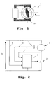
- the electronic device of the invention is applied to a permanent-magnet synchronous motor 1 with a rotor 1A and a stator 1B Said motor 1 has two rotor poles and two stator poles, and is shown purely by way of an example.
- the electronic device for controlling said synchronous motor 1 comprises:
- Said electronic circuit 3 determines the timing for firing the static switch taking as reference the zero-crossing of the mains voltage Vr and applying a firing time Td starting from said reference, said firing time Td being obtained as a function of the position of the rotor 1A of the motor 1 in the previous half-cycles.
- the electronic circuit 3 can choose the direction of rotation of the rotor 1A of the motor 1. To do that, said electronic circuit 3 takes account of the polarity values of the mains voltage Vr and the position of the rotor 1A, so that the static switch 2 fires at the firing times calculated, provided that said values are such as to contribute to the rotation in the direction chosen.
- switch 2 will receive a firing signal once the corresponding time Td has passed after zero-crossing of the mains voltage Vr.
- the electronic circuit 3 calculates the firing time Td according to the phase shifts between the current flowing through the motor 1 and the position of the rotor 1A in the previous half-cycles.
- the electronic circuit 3 calculates the phase shifts produced between the current flowing through the motor 1 and the rotor 1A measuring the phase shifts between the voltage in the static switch 2 received along line 7, and the signal 6 from a position sensor 4 adapted to detect the position of the rotor 1A of the motor 1 (e.g. a Hall effect sensor).
- the control consists of maintaining a phase shift that, as a maximum, equals a predetermined constant value D. In this way, if the phase shift is greater than said value D, said phase shift will tend to approach value D. No action is implemented on the phase shift when it is less than said value D.
- the electronic circuit 3 calculates the phase shift between the Vt voltage in the static switch 2 (considering the moment at which said voltage Vt appears), and the signal 6 of the position sensor 4, then subtracting from said phase shift the constant phase shift D.
- the sum of the subtractions obtained is divided by a whole constant value k.
- Td i +1 Td i + 1 k ( tIo i - th i - D )
- the electronic circuit 3 acts on the switch 2 according to three signals: the mains voltage Vr received along line 5, the signal 6 from the position sensor 4, and the voltage Vt in the switch 2, received along line 7.
- the electronic circuit 3 calculates the firing time Td as a function of the phase shifts produced between the position of the rotor 1A of the motor 1 and the mains voltage Vr in the previous half-cycles.
- the position of the rotor 1A of the motor 1 is also measured from the signal 6 from a position sensor 4.
- a constant phase shift D is also considered.
- the control consists of maintaining as a minimum a phase shift of D. In this way, if the phase shift is less than said value D, said phase shift will tend to approach value D, with no action being taken on the phase shift when it is greater than said value D.
- Td i +1 Td i + 1 k ( tred i - th i + D )
- the electronic circuit 3 acts on the switch 2 in accordance with two signals: the mains voltage Vr and signal 6 from the position sensor 4, voltage Vt at switch 2 not being necessary.
- the reaction capacity of the motor 1 depends on the values of D and k selected.
- D the reaction capacity of the motor 1
- k the value of the reaction capacity of the motor 1
- a higher D value implies enhanced reaction capacity and less power saving
- a lower value for D implies on the contrary less reaction capacity and greater power saving.
- the second embodiment just the contrary occurs.
- the idea is to reach a compromise when calculating the k and D values.
- Simple tests can be used to determine optimal k and D values which depend, among other factors, on the characteristics of the motor 1.
- the constant k can, for example, have a value of the order of 100, and the value of D may, for a k value of said order, fall between 0 and 2.5 ms.
- the electronic device 3 of the invention fires the static switch 2 during several cycles without control (a situation equivalent to a direct connection to the mains voltage Vr) to force the rotor 1A to move from its rest position. It then begins to calculate the firing times based on the Td firing times and to fire the static switch 2 according to those Td firing times, depending on the direction of turn selected, the polarity of the mains voltage Vr and position of rotor 1A.
- the rotor 1A With the current applied at the outset, the rotor 1A can be moved from its position so as acquire sufficient inertia to begin to turn in a given direction. Should rotor 1A have begun to turn in the direction opposite to the one intended, the control applied will brake it in that direction, until it stops and it begins turning in the direction chosen.
Landscapes
- Engineering & Computer Science (AREA)
- Power Engineering (AREA)
- Control Of Motors That Do Not Use Commutators (AREA)
- Control Of Ac Motors In General (AREA)
Abstract
Description
- an alternating voltage source at mains frequency
providing a voltage Vr, connected in series with
said
synchronous motor 1, - a
static switch 2 connected in series with saidsynchronous motor 1 and comprising for example a triac, and - an
electronic circuit 3 which acts on saidstatic switch 2.


Claims (13)
- An electronic device for controlling a synchronous motor with permanent-magnet rotor comprising:characterised in that said electronic circuit (3) calculates the firing instants for the static switch (2) for each half-cycle, taking as reference the zero-crossing of the mains voltage (Vr) and applying a firing time (Td) starting from said reference, said firing time (Td) being obtained as a function of the position of the rotor (1A) of the motor (1) in the previous half-cycles.an alternating voltage current source at mains frequency connected in series with said synchronous motor (1)at least one static switch (2) connected in series with said synchronous motor (1); andan electronic circuit (3) acting on said static switch (2);
- An electronic device according to claim 1, wherein the electronic circuit (3) determines the direction of rotation of the rotor (1A) according to the polarity of the mains voltage (Vr) and the position of the rotor (1A), firing the static switch (2), at the firing instants calculated, provided that the values of the mains voltage (Vr) and the position of rotor (1A) are such as to help rotation in the direction chosen.
- An electronic device according to claims 1 or 2, wherein the electronic circuit (3) calculates the firing time (Td) according to the phase shifts produced between the current flowing through the motor (1) and the position of the rotor (1A) of the motor (1) in the previous half-cycles.
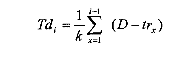
- An electronic device according to claim 3, wherein the electronic circuit (3) determines the firing time (Td) at a given instant i calculated by the following formula:where trx is the phase shift between the current in the static switch (2) and the position of the rotor (1A), D is a constant predetermined phase shift and k is a given constant value.

- An electronic device according to claims 3 or 4, wherein the electronic circuit (3) calculates the phase shifts produced between the current flowing through motor (1) and the position of the rotor (1A) of the motor (1), measuring the phase shifts between the voltage (Vt) in the static switch (2) and the signal (6) from a position sensor (4) adapted to detect the position of the rotor (1A) of the motor (1).
- An electronic device according to claims 1 or 2, wherein the electronic circuit (3) calculates the firing time (Td) according to the phase shifts produced between the position of the rotor (1A) of the motor (1) and the mains voltage (Vr) in the previous half-cycles.
- An electronic device according to claim 6, wherein the electronic circuit (3) calculates the firing time (Td) in a given instant i using the following formula:where trx is the phase shift between the position of the rotor (1A) and the mains voltage (Vr), D is a predetermined constant phase shift, and k is a given constant value.
- An electronic device according to claim 6 or 7, wherein the position of rotor (1A) of the motor (1) is measured from the signal (6) from a position sensor (4).
- An electronic device according to claim 5 or 8, wherein the position sensor (4) is placed at the central point of the free space between the poles of the stator (1B) of the motor (1).
- An electronic device according to any of the preceding claims, wherein, on initiating startup of the motor (1), the electronic circuit (3) fires the static switch (2) during several cycles, without control, to cause the rotor (1A) to move from its rest position, and then begins to calculate the firing instants based on the firing times (Td), and to fire the static switch (2) depending on said firing times (Td).
- An electronic device according to claim 10, wherein if, following initiation of the startup, the time during which the rotor (1A) polarity remains the same exceeds a predetermined value, said startup is initiated once more.
- An electronic device according to any of the preceding claims, wherein, when the time (trot) taken by the rotor (1A) of the motor (1) to rotate a half turn is less than the time of one half-cycle (Tred) of the mains voltage (Vr), a delay (δ) is applied to the firing time (Td).
- An electronic device according to claim 12, wherein the delay (δ) equals the difference between the time (Tred) of one half-cycle of the mains voltage (Vr) and the time (trot) taken by the rotor (1A) of the motor (1) to rotate a half turn.
Applications Claiming Priority (2)
| Application Number | Priority Date | Filing Date | Title |
|---|---|---|---|
| ES200201408A ES2197822B1 (en) | 2002-06-18 | 2002-06-18 | ELECTRONIC DEVICE FOR THE CONTROL OF A SYNCHRONOUS MOTOR WITH PERMANENT MAGNET ROTOR. |
| ES200201408 | 2002-06-18 |
Publications (3)
| Publication Number | Publication Date |
|---|---|
| EP1376848A2 true EP1376848A2 (en) | 2004-01-02 |
| EP1376848A3 EP1376848A3 (en) | 2006-05-10 |
| EP1376848B1 EP1376848B1 (en) | 2011-04-20 |
Family
ID=29717043
Family Applications (1)
| Application Number | Title | Priority Date | Filing Date |
|---|---|---|---|
| EP03380132A Expired - Lifetime EP1376848B1 (en) | 2002-06-18 | 2003-06-03 | Electronic device for controlling a synchronous motor with permanent-magnet rotor |
Country Status (5)
| Country | Link |
|---|---|
| US (1) | US6885161B2 (en) |
| EP (1) | EP1376848B1 (en) |
| AT (1) | ATE506739T1 (en) |
| DE (1) | DE60336785D1 (en) |
| ES (2) | ES2197822B1 (en) |
Cited By (2)
| Publication number | Priority date | Publication date | Assignee | Title |
|---|---|---|---|---|
| CN104979982A (en) * | 2015-07-01 | 2015-10-14 | 江门市地尔汉宇电器股份有限公司 | Miniature single-phase permanent-magnet synchronous motor |
| CN105048899A (en) * | 2015-07-15 | 2015-11-11 | 江门市地尔汉宇电器股份有限公司 | Miniature single-phase permanent-magnet synchronous motor |
Families Citing this family (28)
| Publication number | Priority date | Publication date | Assignee | Title |
|---|---|---|---|---|
| EP1351376A1 (en) * | 2002-03-11 | 2003-10-08 | Askoll Holding S.r.l. | Electronic device for starting and controlling a permanent-magnet synchronous motor |
| DE50311997D1 (en) * | 2003-01-21 | 2009-11-19 | Grundfos As | Method for controlling the ignition angle and single phase AC powered electric motor |
| DK1512949T3 (en) * | 2003-09-04 | 2007-05-14 | Askoll Holding Srl | Method and apparatus for determining the hydraulic flow rate in a pump |
| ITTO20060023A1 (en) * | 2006-01-13 | 2007-07-14 | Elbi Int Spa | CONTROL DEVICE FOR A SYNCHRONOUS ELECTRIC MOTOR |
| ITTO20070459A1 (en) * | 2007-06-26 | 2008-12-27 | Emerson Appliance Motors Europe | CONTROL SYSTEM WITHOUT POSITION SENSORS FOR A SYNCHRONOUS ELECTRIC MOTOR |
| ITTO20070458A1 (en) * | 2007-06-26 | 2008-12-27 | Emerson Appliance Motors Europe | CONTROL SYSTEM OF THE ROTATION AT THE HEIGHT OF A SYNCHRONOUS ELECTRIC MOTOR |
| EP2238270A2 (en) * | 2007-12-21 | 2010-10-13 | Cook Incorporated | Radiopaque alloy and medical device made of this alloy |
| GB201006395D0 (en) | 2010-04-16 | 2010-06-02 | Dyson Technology Ltd | Control of a brushless motor |
| GB201006388D0 (en) | 2010-04-16 | 2010-06-02 | Dyson Technology Ltd | Control of brushless motor |
| GB201006397D0 (en) | 2010-04-16 | 2010-06-02 | Dyson Technology Ltd | Control of a brushless motor |
| GB201006387D0 (en) * | 2010-04-16 | 2010-06-02 | Dyson Technology Ltd | Control of a brushless motor |
| GB201006392D0 (en) | 2010-04-16 | 2010-06-02 | Dyson Technology Ltd | Controller for a brushless motor |
| GB201006398D0 (en) | 2010-04-16 | 2010-06-02 | Dyson Technology Ltd | Control of a brushless motor |
| GB201006386D0 (en) | 2010-04-16 | 2010-06-02 | Dyson Technology Ltd | Control of a brushless motor |
| GB201006390D0 (en) | 2010-04-16 | 2010-06-02 | Dyson Technology Ltd | Control of a brushless motor |
| GB201006396D0 (en) | 2010-04-16 | 2010-06-02 | Dyson Technology Ltd | Control of a brushless motor |
| GB201006391D0 (en) | 2010-04-16 | 2010-06-02 | Dyson Technology Ltd | Control of a brushless permanent-magnet motor |
| SI2410653T1 (en) * | 2010-07-23 | 2019-07-31 | Askoll Holding S.R.L. | Device for controlling a synchronous electric motor with a permanent magnet rotor |
| GB2484289B (en) | 2010-10-04 | 2013-11-20 | Dyson Technology Ltd | Control of an electrical machine |
| US10312798B2 (en) | 2016-04-15 | 2019-06-04 | Emerson Electric Co. | Power factor correction circuits and methods including partial power factor correction operation for boost and buck power converters |
| US10763740B2 (en) | 2016-04-15 | 2020-09-01 | Emerson Climate Technologies, Inc. | Switch off time control systems and methods |
| US10277115B2 (en) | 2016-04-15 | 2019-04-30 | Emerson Climate Technologies, Inc. | Filtering systems and methods for voltage control |
| US9933842B2 (en) | 2016-04-15 | 2018-04-03 | Emerson Climate Technologies, Inc. | Microcontroller architecture for power factor correction converter |
| US10656026B2 (en) | 2016-04-15 | 2020-05-19 | Emerson Climate Technologies, Inc. | Temperature sensing circuit for transmitting data across isolation barrier |
| US10284132B2 (en) | 2016-04-15 | 2019-05-07 | Emerson Climate Technologies, Inc. | Driver for high-frequency switching voltage converters |
| US10305373B2 (en) | 2016-04-15 | 2019-05-28 | Emerson Climate Technologies, Inc. | Input reference signal generation systems and methods |
| CN109687780A (en) * | 2017-08-25 | 2019-04-26 | 德昌电机(深圳)有限公司 | Motor and its driving circuit and driving method |
| JP7050624B2 (en) * | 2018-08-24 | 2022-04-08 | 日立Astemo株式会社 | Motor control device and electric brake device equipped with it |
Family Cites Families (11)
| Publication number | Priority date | Publication date | Assignee | Title |
|---|---|---|---|---|
| JPS4921488B1 (en) * | 1967-03-24 | 1974-06-01 | ||
| DE3507883A1 (en) * | 1985-03-06 | 1986-09-18 | Deutsche Thomson-Brandt Gmbh, 7730 Villingen-Schwenningen | CIRCUIT TO CONTROL A BRUSHLESS ELECTRIC MOTOR |
| DE3517570A1 (en) * | 1985-05-15 | 1986-11-20 | Deutsche Thomson-Brandt Gmbh, 7730 Villingen-Schwenningen | CIRCUIT TO CONTROL A BRUSHLESS ELECTRIC MOTOR |
| IT1259115B (en) * | 1992-06-17 | 1996-03-11 | Askoll Spa | ELECTRONIC DEVICE FOR STARTING A SYNCHRONOUS MOTOR WITH PERMANENT MAGNET ROTOR |
| IT1269755B (en) * | 1994-05-11 | 1997-04-15 | Sisme | ELECTRONIC DEVICE FOR STARTING AND CONTROL OF A SINGLE-PHASE SYNCHRONOUS MOTOR WITH PERMANENT MAGNETS |
| IT1271327B (en) * | 1994-12-23 | 1997-05-27 | Sisme | METHOD AND RELATED CONTROL DEVICE OF A SINGLE-PHASE SYNCHRONOUS MOTOR WITH PERMANENT MAGNETS SUITABLE TO OPTIMIZE THE OPERATING PARAMETERS EVEN IN THE PRESENCE OF OSCILLATIONS OF THE SUPPLY VOLTAGE OR THE LOAD APPLIED |
| US5675226A (en) * | 1995-09-06 | 1997-10-07 | C.E.Set. S.R.L. | Control circuit for an synchronous electric motor of the brushless type |
| DE19701856A1 (en) * | 1997-01-21 | 1998-07-23 | Wunnibald Kunz | Electronic start-up and operation control for a single-phase synchronous motor |
| IT1295316B1 (en) * | 1997-10-10 | 1999-05-04 | Sisme Immobiliare S P A | SINGLE-PHASE SYNCHRONOUS MOTOR WITH PERMANENT MAGNET ROTOR |
| ITTO980027A1 (en) * | 1998-01-15 | 1999-07-15 | Plaset Srl | PILOTING CIRCUIT FOR A SYNCHRONOUS ELECTRIC MOTOR IN CURRENT TO THE TERNATA. |
| IT1304666B1 (en) * | 1998-10-01 | 2001-03-28 | Plaset Spa | SYNCHRONOUS ELECTRIC MOTOR. |
-
2002
- 2002-06-18 ES ES200201408A patent/ES2197822B1/en not_active Expired - Fee Related
-
2003
- 2003-06-03 DE DE60336785T patent/DE60336785D1/en not_active Expired - Lifetime
- 2003-06-03 AT AT03380132T patent/ATE506739T1/en not_active IP Right Cessation
- 2003-06-03 ES ES03380132T patent/ES2361830T3/en not_active Expired - Lifetime
- 2003-06-03 EP EP03380132A patent/EP1376848B1/en not_active Expired - Lifetime
- 2003-06-12 US US10/461,762 patent/US6885161B2/en not_active Expired - Lifetime
Cited By (4)
| Publication number | Priority date | Publication date | Assignee | Title |
|---|---|---|---|---|
| CN104979982A (en) * | 2015-07-01 | 2015-10-14 | 江门市地尔汉宇电器股份有限公司 | Miniature single-phase permanent-magnet synchronous motor |
| CN104979982B (en) * | 2015-07-01 | 2017-09-12 | 江门市地尔汉宇电器股份有限公司 | A kind of miniature single-phase permanent-magnet synchronous motor |
| CN105048899A (en) * | 2015-07-15 | 2015-11-11 | 江门市地尔汉宇电器股份有限公司 | Miniature single-phase permanent-magnet synchronous motor |
| CN105048899B (en) * | 2015-07-15 | 2017-06-13 | 江门市地尔汉宇电器股份有限公司 | A kind of miniature single-phase permanent-magnet synchronous motor |
Also Published As
| Publication number | Publication date |
|---|---|
| ES2361830T3 (en) | 2011-06-22 |
| ES2197822B1 (en) | 2005-09-16 |
| ATE506739T1 (en) | 2011-05-15 |
| US6885161B2 (en) | 2005-04-26 |
| EP1376848B1 (en) | 2011-04-20 |
| US20030230999A1 (en) | 2003-12-18 |
| EP1376848A3 (en) | 2006-05-10 |
| DE60336785D1 (en) | 2011-06-01 |
| ES2197822A1 (en) | 2004-01-01 |
Similar Documents
| Publication | Publication Date | Title |
|---|---|---|
| US6885161B2 (en) | Electronic device for controlling a synchronous motor with permanent-magnet rotor | |
| KR101521199B1 (en) | Control of an electrical machine | |
| EP1121753B1 (en) | Method and device for controlling a brushless electric motor | |
| US4767976A (en) | Control system for PWM inverter | |
| EP3540933B1 (en) | Method for driving sensorless motor | |
| JP5281339B2 (en) | Synchronous motor drive system and control device used therefor | |
| KR100791814B1 (en) | Sensorless BCD Motor Control Method | |
| EP1612925A2 (en) | A brushless DC motor controller | |
| KR102426117B1 (en) | System and method for controlling motor | |
| EP1406376A2 (en) | Speed-based open-loop start-up method for brushless DC motor | |
| JP2000166300A (en) | Start control device for permanent magnet synchronous motor | |
| CN101248577B (en) | Asymmetric control system for a sensorless and brushless electric motor | |
| EP1594219A2 (en) | Motor controller and out-of-control detecting method | |
| EP1774644B1 (en) | Drive circuit for a synchronous electric motor | |
| JP2011024401A (en) | Starting method and driving method for brushless motor, and driving device for the same | |
| JP6440355B2 (en) | Method and apparatus for synchronizing rotor speed with stator rotating magnetic field | |
| JP3296636B2 (en) | Driving method of brushless DC motor | |
| RU2014720C1 (en) | Method of starting and self-starting of synchronous motor | |
| US6781334B2 (en) | Motor controller and control method thereof | |
| SU1037403A1 (en) | Method and apparatus for controlling induction electric motor | |
| JP2005278360A (en) | Brushless motor sensorless controlling method, sensorless controller thereof, and electric pump | |
| JPH06303787A (en) | Induction motor DC braking control method | |
| JP2000004598A (en) | Stepping motor device with position sensor | |
| JPH04140093A (en) | Motor driving circuit | |
| SU904135A1 (en) | Thyratron electric motor |
Legal Events
| Date | Code | Title | Description |
|---|---|---|---|
| PUAI | Public reference made under article 153(3) epc to a published international application that has entered the european phase |
Free format text: ORIGINAL CODE: 0009012 |
|
| AK | Designated contracting states |
Kind code of ref document: A2 Designated state(s): AT BE BG CH CY CZ DE DK EE ES FI FR GB GR HU IE IT LI LU MC NL PT RO SE SI SK TR |
|
| AX | Request for extension of the european patent |
Extension state: AL LT LV MK |
|
| PUAL | Search report despatched |
Free format text: ORIGINAL CODE: 0009013 |
|
| AK | Designated contracting states |
Kind code of ref document: A3 Designated state(s): AT BE BG CH CY CZ DE DK EE ES FI FR GB GR HU IE IT LI LU MC NL PT RO SE SI SK TR |
|
| AX | Request for extension of the european patent |
Extension state: AL LT LV MK |
|
| RAP1 | Party data changed (applicant data changed or rights of an application transferred) |
Owner name: COPRECITEC, S.L. |
|
| 17P | Request for examination filed |
Effective date: 20060906 |
|
| AKX | Designation fees paid |
Designated state(s): AT BE BG CH CY CZ DE DK EE ES FI FR GB GR HU IE IT LI LU MC NL PT RO SE SI SK TR |
|
| 17Q | First examination report despatched |
Effective date: 20070312 |
|
| GRAP | Despatch of communication of intention to grant a patent |
Free format text: ORIGINAL CODE: EPIDOSNIGR1 |
|
| GRAS | Grant fee paid |
Free format text: ORIGINAL CODE: EPIDOSNIGR3 |
|
| GRAA | (expected) grant |
Free format text: ORIGINAL CODE: 0009210 |
|
| AK | Designated contracting states |
Kind code of ref document: B1 Designated state(s): AT BE BG CH CY CZ DE DK EE ES FI FR GB GR HU IE IT LI LU MC NL PT RO SE SI SK TR |
|
| REG | Reference to a national code |
Ref country code: GB Ref legal event code: FG4D |
|
| REG | Reference to a national code |
Ref country code: CH Ref legal event code: EP |
|
| REG | Reference to a national code |
Ref country code: IE Ref legal event code: FG4D |
|
| REF | Corresponds to: |
Ref document number: 60336785 Country of ref document: DE Date of ref document: 20110601 Kind code of ref document: P |
|
| REG | Reference to a national code |
Ref country code: DE Ref legal event code: R096 Ref document number: 60336785 Country of ref document: DE Effective date: 20110601 |
|
| REG | Reference to a national code |
Ref country code: ES Ref legal event code: FG2A Ref document number: 2361830 Country of ref document: ES Kind code of ref document: T3 Effective date: 20110622 |
|
| REG | Reference to a national code |
Ref country code: NL Ref legal event code: VDEP Effective date: 20110420 |
|
| PG25 | Lapsed in a contracting state [announced via postgrant information from national office to epo] |
Ref country code: PT Free format text: LAPSE BECAUSE OF FAILURE TO SUBMIT A TRANSLATION OF THE DESCRIPTION OR TO PAY THE FEE WITHIN THE PRESCRIBED TIME-LIMIT Effective date: 20110822 Ref country code: SE Free format text: LAPSE BECAUSE OF FAILURE TO SUBMIT A TRANSLATION OF THE DESCRIPTION OR TO PAY THE FEE WITHIN THE PRESCRIBED TIME-LIMIT Effective date: 20110420 |
|
| PG25 | Lapsed in a contracting state [announced via postgrant information from national office to epo] |
Ref country code: FI Free format text: LAPSE BECAUSE OF FAILURE TO SUBMIT A TRANSLATION OF THE DESCRIPTION OR TO PAY THE FEE WITHIN THE PRESCRIBED TIME-LIMIT Effective date: 20110420 Ref country code: BE Free format text: LAPSE BECAUSE OF FAILURE TO SUBMIT A TRANSLATION OF THE DESCRIPTION OR TO PAY THE FEE WITHIN THE PRESCRIBED TIME-LIMIT Effective date: 20110420 Ref country code: SI Free format text: LAPSE BECAUSE OF FAILURE TO SUBMIT A TRANSLATION OF THE DESCRIPTION OR TO PAY THE FEE WITHIN THE PRESCRIBED TIME-LIMIT Effective date: 20110420 Ref country code: AT Free format text: LAPSE BECAUSE OF FAILURE TO SUBMIT A TRANSLATION OF THE DESCRIPTION OR TO PAY THE FEE WITHIN THE PRESCRIBED TIME-LIMIT Effective date: 20110420 Ref country code: GR Free format text: LAPSE BECAUSE OF FAILURE TO SUBMIT A TRANSLATION OF THE DESCRIPTION OR TO PAY THE FEE WITHIN THE PRESCRIBED TIME-LIMIT Effective date: 20110721 Ref country code: CY Free format text: LAPSE BECAUSE OF FAILURE TO SUBMIT A TRANSLATION OF THE DESCRIPTION OR TO PAY THE FEE WITHIN THE PRESCRIBED TIME-LIMIT Effective date: 20110420 |
|
| PG25 | Lapsed in a contracting state [announced via postgrant information from national office to epo] |
Ref country code: NL Free format text: LAPSE BECAUSE OF FAILURE TO SUBMIT A TRANSLATION OF THE DESCRIPTION OR TO PAY THE FEE WITHIN THE PRESCRIBED TIME-LIMIT Effective date: 20110420 |
|
| PG25 | Lapsed in a contracting state [announced via postgrant information from national office to epo] |
Ref country code: EE Free format text: LAPSE BECAUSE OF FAILURE TO SUBMIT A TRANSLATION OF THE DESCRIPTION OR TO PAY THE FEE WITHIN THE PRESCRIBED TIME-LIMIT Effective date: 20110420 Ref country code: CZ Free format text: LAPSE BECAUSE OF FAILURE TO SUBMIT A TRANSLATION OF THE DESCRIPTION OR TO PAY THE FEE WITHIN THE PRESCRIBED TIME-LIMIT Effective date: 20110420 |
|
| REG | Reference to a national code |
Ref country code: CH Ref legal event code: PL |
|
| PLBE | No opposition filed within time limit |
Free format text: ORIGINAL CODE: 0009261 |
|
| STAA | Information on the status of an ep patent application or granted ep patent |
Free format text: STATUS: NO OPPOSITION FILED WITHIN TIME LIMIT |
|
| PG25 | Lapsed in a contracting state [announced via postgrant information from national office to epo] |
Ref country code: SK Free format text: LAPSE BECAUSE OF FAILURE TO SUBMIT A TRANSLATION OF THE DESCRIPTION OR TO PAY THE FEE WITHIN THE PRESCRIBED TIME-LIMIT Effective date: 20110420 Ref country code: DK Free format text: LAPSE BECAUSE OF FAILURE TO SUBMIT A TRANSLATION OF THE DESCRIPTION OR TO PAY THE FEE WITHIN THE PRESCRIBED TIME-LIMIT Effective date: 20110420 Ref country code: RO Free format text: LAPSE BECAUSE OF FAILURE TO SUBMIT A TRANSLATION OF THE DESCRIPTION OR TO PAY THE FEE WITHIN THE PRESCRIBED TIME-LIMIT Effective date: 20110420 |
|
| 26N | No opposition filed |
Effective date: 20120123 |
|
| REG | Reference to a national code |
Ref country code: IE Ref legal event code: MM4A |
|
| PG25 | Lapsed in a contracting state [announced via postgrant information from national office to epo] |
Ref country code: LI Free format text: LAPSE BECAUSE OF NON-PAYMENT OF DUE FEES Effective date: 20110630 Ref country code: IE Free format text: LAPSE BECAUSE OF NON-PAYMENT OF DUE FEES Effective date: 20110603 Ref country code: CH Free format text: LAPSE BECAUSE OF NON-PAYMENT OF DUE FEES Effective date: 20110630 |
|
| REG | Reference to a national code |
Ref country code: DE Ref legal event code: R097 Ref document number: 60336785 Country of ref document: DE Effective date: 20120123 |
|
| PG25 | Lapsed in a contracting state [announced via postgrant information from national office to epo] |
Ref country code: MC Free format text: LAPSE BECAUSE OF NON-PAYMENT OF DUE FEES Effective date: 20110630 |
|
| PG25 | Lapsed in a contracting state [announced via postgrant information from national office to epo] |
Ref country code: LU Free format text: LAPSE BECAUSE OF NON-PAYMENT OF DUE FEES Effective date: 20110603 |
|
| PG25 | Lapsed in a contracting state [announced via postgrant information from national office to epo] |
Ref country code: BG Free format text: LAPSE BECAUSE OF FAILURE TO SUBMIT A TRANSLATION OF THE DESCRIPTION OR TO PAY THE FEE WITHIN THE PRESCRIBED TIME-LIMIT Effective date: 20110720 |
|
| PG25 | Lapsed in a contracting state [announced via postgrant information from national office to epo] |
Ref country code: TR Free format text: LAPSE BECAUSE OF FAILURE TO SUBMIT A TRANSLATION OF THE DESCRIPTION OR TO PAY THE FEE WITHIN THE PRESCRIBED TIME-LIMIT Effective date: 20110420 |
|
| PG25 | Lapsed in a contracting state [announced via postgrant information from national office to epo] |
Ref country code: HU Free format text: LAPSE BECAUSE OF FAILURE TO SUBMIT A TRANSLATION OF THE DESCRIPTION OR TO PAY THE FEE WITHIN THE PRESCRIBED TIME-LIMIT Effective date: 20110420 |
|
| REG | Reference to a national code |
Ref country code: FR Ref legal event code: PLFP Year of fee payment: 14 |
|
| REG | Reference to a national code |
Ref country code: FR Ref legal event code: PLFP Year of fee payment: 15 |
|
| REG | Reference to a national code |
Ref country code: FR Ref legal event code: PLFP Year of fee payment: 16 |
|
| PGFP | Annual fee paid to national office [announced via postgrant information from national office to epo] |
Ref country code: FR Payment date: 20180626 Year of fee payment: 16 |
|
| PGFP | Annual fee paid to national office [announced via postgrant information from national office to epo] |
Ref country code: ES Payment date: 20180704 Year of fee payment: 16 Ref country code: IT Payment date: 20180621 Year of fee payment: 16 Ref country code: DE Payment date: 20180627 Year of fee payment: 16 Ref country code: GB Payment date: 20180627 Year of fee payment: 16 |
|
| REG | Reference to a national code |
Ref country code: DE Ref legal event code: R119 Ref document number: 60336785 Country of ref document: DE |
|
| GBPC | Gb: european patent ceased through non-payment of renewal fee |
Effective date: 20190603 |
|
| PG25 | Lapsed in a contracting state [announced via postgrant information from national office to epo] |
Ref country code: IT Free format text: LAPSE BECAUSE OF NON-PAYMENT OF DUE FEES Effective date: 20190603 Ref country code: DE Free format text: LAPSE BECAUSE OF NON-PAYMENT OF DUE FEES Effective date: 20200101 Ref country code: GB Free format text: LAPSE BECAUSE OF NON-PAYMENT OF DUE FEES Effective date: 20190603 |
|
| PG25 | Lapsed in a contracting state [announced via postgrant information from national office to epo] |
Ref country code: FR Free format text: LAPSE BECAUSE OF NON-PAYMENT OF DUE FEES Effective date: 20190630 |
|
| REG | Reference to a national code |
Ref country code: ES Ref legal event code: FD2A Effective date: 20201027 |
|
| PG25 | Lapsed in a contracting state [announced via postgrant information from national office to epo] |
Ref country code: ES Free format text: LAPSE BECAUSE OF NON-PAYMENT OF DUE FEES Effective date: 20190604 |