EP1376471A1 - Verfahren der Bewegungsschätzung zur Stabilisierung einer Bildsequenz - Google Patents
Verfahren der Bewegungsschätzung zur Stabilisierung einer Bildsequenz Download PDFInfo
- Publication number
- EP1376471A1 EP1376471A1 EP02425402A EP02425402A EP1376471A1 EP 1376471 A1 EP1376471 A1 EP 1376471A1 EP 02425402 A EP02425402 A EP 02425402A EP 02425402 A EP02425402 A EP 02425402A EP 1376471 A1 EP1376471 A1 EP 1376471A1
- Authority
- EP
- European Patent Office
- Prior art keywords
- block
- image
- motion vector
- motion
- accordance
- Prior art date
- Legal status (The legal status is an assumption and is not a legal conclusion. Google has not performed a legal analysis and makes no representation as to the accuracy of the status listed.)
- Withdrawn
Links
- 230000033001 locomotion Effects 0.000 title claims abstract description 237
- 230000006641 stabilisation Effects 0.000 title claims description 30
- 238000011105 stabilization Methods 0.000 title claims description 30
- 239000013598 vector Substances 0.000 claims abstract description 96
- 238000000034 method Methods 0.000 claims abstract description 75
- 239000011159 matrix material Substances 0.000 claims abstract description 5
- 230000000087 stabilizing effect Effects 0.000 claims description 3
- 238000013519 translation Methods 0.000 description 13
- 230000004913 activation Effects 0.000 description 8
- 238000012937 correction Methods 0.000 description 8
- 238000012545 processing Methods 0.000 description 7
- 230000008901 benefit Effects 0.000 description 6
- 238000004364 calculation method Methods 0.000 description 5
- 230000002747 voluntary effect Effects 0.000 description 5
- 230000006870 function Effects 0.000 description 4
- 238000007781 pre-processing Methods 0.000 description 4
- 239000003381 stabilizer Substances 0.000 description 4
- 230000006835 compression Effects 0.000 description 3
- 238000007906 compression Methods 0.000 description 3
- 230000000875 corresponding effect Effects 0.000 description 3
- 238000001914 filtration Methods 0.000 description 3
- 230000003287 optical effect Effects 0.000 description 3
- 238000004091 panning Methods 0.000 description 3
- 238000004891 communication Methods 0.000 description 2
- 230000002596 correlated effect Effects 0.000 description 2
- 238000011156 evaluation Methods 0.000 description 2
- 230000004048 modification Effects 0.000 description 2
- 238000012986 modification Methods 0.000 description 2
- 230000010355 oscillation Effects 0.000 description 2
- 230000003044 adaptive effect Effects 0.000 description 1
- 230000006399 behavior Effects 0.000 description 1
- 238000006243 chemical reaction Methods 0.000 description 1
- 230000000295 complement effect Effects 0.000 description 1
- 230000007547 defect Effects 0.000 description 1
- 238000006073 displacement reaction Methods 0.000 description 1
- 230000000694 effects Effects 0.000 description 1
- 238000005516 engineering process Methods 0.000 description 1
- 230000010354 integration Effects 0.000 description 1
- 229910044991 metal oxide Inorganic materials 0.000 description 1
- 150000004706 metal oxides Chemical class 0.000 description 1
- 238000010295 mobile communication Methods 0.000 description 1
- 238000005457 optimization Methods 0.000 description 1
- 230000002093 peripheral effect Effects 0.000 description 1
- 230000008569 process Effects 0.000 description 1
- 230000005855 radiation Effects 0.000 description 1
- 238000009877 rendering Methods 0.000 description 1
- 239000004065 semiconductor Substances 0.000 description 1
- 230000035945 sensitivity Effects 0.000 description 1
- 230000003595 spectral effect Effects 0.000 description 1
- 230000009466 transformation Effects 0.000 description 1
- 230000007704 transition Effects 0.000 description 1
- 230000021542 voluntary musculoskeletal movement Effects 0.000 description 1
Images


Classifications
-
- G—PHYSICS
- G06—COMPUTING; CALCULATING OR COUNTING
- G06T—IMAGE DATA PROCESSING OR GENERATION, IN GENERAL
- G06T7/00—Image analysis
- G06T7/20—Analysis of motion
- G06T7/215—Motion-based segmentation
Definitions
- the present invention is concerned with digital image processing and, more particularly, regards a motion estimation method and a stabilization method for an image sequence.
- Digital images are nowadays used in many different applications, a case in point being such traditional acquisition devices as digital still and video cameras.
- the acquisition rate of the sequence i.e. the number of images acquired in a given time interval, may vary in accordance with the specific applications; for example, the rate will be very high in digital video cameras (about 25 images per second) and lower in mobile communication terminals (about 15 images per second) that acquire the digital images and transmit them in real time to a remote terminal.
- the number of digital images comprised in the sequence can likewise vary within wide limits: for example, the sequence may contain a large number of images (video sequence), but there are also many known specific applications of digital photography for which it is sufficient to acquire sequences containing just a few images (two or three, for example).
- image sequences are often affected by unwanted displacements/motions between images produced in the acquisition phase.
- unwanted motions may be due to, for example, vibrations, fluctuations or micro-oscillations of the acquisition device during the acquisition of the sequence.
- the stabilization of video sequences plays an important part, because - as is well known to persons skilled in the art - it not only eliminates unpleasant oscillations and vibrations that would be visible in the reproduction of these sequences (a film, for example), but also makes it possible to obtain a greater compression efficiency when the sequences are encoded by means of encoding /compression techniques that operate, for example, in accordance with the MPEG standard or the H263 standard and are nowadays extensively used in the greater part of the available commercial devices.
- both the alignment/registration techniques and the stabilization techniques correct the acquired sequence after a phase of estimating the relative motions between image pairs of the sequence.
- This phase which will hereinafter be referred to as the motion estimation (or Mot Est) phase, produces an estimate of the motion of the sequence by evaluating, for example, the motion of each image of the sequence with respect to a reference image.
- the present invention therefore sets out to provide a motion estimation method for an image sequence that will not give rise to the drawbacks associated with the prior art methods. This aim is attained by a motion estimation method as described in Claims 1 to 15 hereinbelow.
- a further aim of the present invention is to provide a stabilization method as described in Claims 16 to 20.
- Another aim of the present invention is to provide an acquisition device as described in Claims 21 and 22.
- the preferred embodiment of the present invention concerns a portable device capable of acquiring digital images for video applications and, more particularly, a motion estimation method for a sequence of images in a digital video camera and a method of stabilizing the sequence.
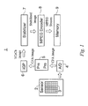
- Figure 1 shows the function blocks of a digital video camera 1.
- the video camera 1 includes an acquisition block 2 comprising an optical sensor 3.
- the sensor 3 which may either a CCD (Charge Coupled Device) or a CMOS (Complementary Metal Oxide Semiconductor), is an integrated circuit comprising a matrix of photosensitive cells, each of which serves to generate an electric signal proportional to the quantity of light that strikes it during the acquisition interval.
- CCD Charge Coupled Device
- CMOS Complementary Metal Oxide Semiconductor
- the senor 3 comprises an optical CFA (Colour Filter Array) filter, for example, a Bayer filter.
- an optical CFA Cold Filter Array
- a Bayer filter As is well known to persons skilled in the art, in a sensor with a CFA filter only a single photosensitive cell is available for acquiring a pixel.
- the sensor is covered by an optical filter constituted by a matrix (a Bayer matrix in this example) of filtering elements, each of which is associated with a photosensitive cell.
- Each filtering element transmits to the photosensitive cell associated with it the light radiation corresponding to the wavelength of only red light, only green light or only blue light, so that for each pixel it detects only one component (of which it absorbs no more than a minimal part).
- the video camera 1 also includes an analog/digital (A/D) conversion block, indicated by the reference number 4, to translate the generated electric signal into a digital value with a predetermined number of bits (generally 8, 10 or 12 bits).
- A/D analog/digital
- the A/D converter 4 is such as to encode the incoming analog signals with eight-bit digital values. In that case the digital values of the pixels will be comprised between a minimum binary value equal to 0 and a maximum binary value equal to 255.
- each pixel is constituted by just a single chromatic component (R, G or B). For this reason, a single one-byte digital value is associated with each pixel.
- a pre-processing (PrePro) block 5 active before and during the entire acquisition phase, is such as to interact with the acquisition block 2 and to extract from the CFA image a number of parameters useful for carrying out automatic control functions: self-focusing, automatic exposure, correction of sensor defects and white balancing.
- a block 6 the so-called IGP (Image Generation Pipeline) block, is designed to perform a processing phase that, starting from the digital CFA image, will produce a complete digital image - YCrCb format, for example - in which each pixel will have associated with it three digital values (i.e. a total of 24 bits) corresponding to a luminance component Y and two chrominance components Cr and Cb.
- This transformation obtained - for example - by means of interpolation, involves a passage from a representation of the image in a single plane (Bayer plane), though containing information relating to different chromatic components, to a representation in three planes.
- the IGP block is commonly realized in the form of a dedicated processor (CFA processor), which may be, for example, in VLSI (Very Large Scale Integration) technology.
- CFA processor dedicated processor
- VLSI Very Large Scale Integration
- the IGP block 6 is also such as to perform various functions for improving the quality of the image, including, for example, filtering the noise introduced by the sensor 3, applying special effects and other functions that will generally vary from one producer to another.
- the video camera 1 preferably comprises a stabilizer block 7 that follows the IGP block 6 and is intended to perform the operations relating to the stabilization method in accordance with the present invention, so that its output will consist of a stabilized sequence of digital images.
- a compression/encoding block 8 which in this example is of the MPEG type (but could also be of other types, H263 for example), and a memory unit 9.
- the sequence images are acquired consecutively by means of the acquisition block 2, preferably within a brief time interval between one image and the next.
- the MPEG-4 standard for example, requires fifteen images to be acquired per second.
- Img 1 represents the first image of the sequence to be acquired
- Img 2 represents the second image, and so on.
- each image is passed to the subsequent blocks, so that in all the subsequent processing phases the images will still be processed consecutively.
- the micro-oscillations of the video camera 1 due to involuntary micro-motions of the user's hand between one acquisition and the next will generate image sequences affected by unwanted motions.
- the sequence may also contain motions purposely introduced by the operator.
- the operator may want to enlarge or reduce the field of view (zooming), or he may voluntarily move the camera to obtain a panoramic view or follow a moving personage (panning).
- each image of the sequence is converted into digital values by the A/D converter 4 and then processed by the pre-processing block 5.
- each CFA image is sent to the IGP block 6.
- the image is subjected to an interpolation phase and is thus transformed into a complete image, for example, in YCrCb format.
- the interpolation phase may be performed, among others, with methods that are know to a person skilled in the art and are therefore obvious from the previous description.
- the interpolated image in YCrCb format is then sent to the stabilizer block 7, where it undergoes processing phase by means of a stabilization method in accordance with the present invention.
- This processing phase produces a stabilized image as its output.
- the choice that the stabilizer block should operate on an image in YCrCb format constitutes a preference and is not limitative for the purposes of the present invention.
- the stabilization method operates on interpolated to be considered as limitative: as will subsequently be explained, a possible alternative consists of applying the stabilization methods to the CFA images.
- each image is sent to the MPEG encoder block 8, which produces as its output a sequence or stream of images encoded/compressed in accordance to an MPEG-type encoding.
- the MPEG stream of compressed images may be registered in a memory unit 9 or sent to an external peripheral device.
- the stabilization method 10, performed in the stabilizer block 7 comprises substantially three successive phases, namely: a first phase 11 of motion estimation (Mot_Est), a second phase 12 of unwanted motion estimation (Unw_Mot_Est) and a third phase 13 of unwanted motion compensation/correction (Unw_Mot_Comp).
- the first phase 11 of motion estimation (Mot_Est) is such as to estimate the motion between images of the sequence.
- the motion estimated by this phase may be due either to a voluntary motion of the operator or to an unwanted motion.
- the motion estimation phase 11 produces an absolute vector of global motion absGMV[n,ref] that comprises a translation component in the horizontal direction absGMV x [n,ref] and a translation component in the vertical direction absGMV Y [n, ref].
- the absolute global motion vector absGMV[n,ref] represents the estimation of the translation motion of the input image Img n with respect to a previous image of the sequence Img ref , which is considered as the reference image.
- the estimation absGMV[n,ref] of the absolute global motion vector of an input image Img n with respect to the reference image Img ref is produced by estimating a global motion vector GMV[n,n-1] of the input image Img n with respect to the image Img n - 1 that immediately precedes it and then adding this vector to the absolute global motion vector absGMV[n-1, ref] estimated for the previous image Img n-1 .
- the second phase 12 which estimates the unwanted motion, is such as to produce for each image Img n an estimation of the unwanted motion by starting from the absolute global motion vector absGMV[n,ref] estimated in the first Mot_Est phase 11.
- a third phase 13 is such as to process the input image Img n in such a manner as to compensate the unwanted motion on the basis of the estimation of this motion produced in the second Unw_Mot_Est phase 12.
- the problem of estimating the motion of the Mot_Est phase 11 is therefore that of estimating a global motion vector between consecutive images of the sequence.
- this global motion vector can be advantageously estimated by starting from the estimation of a plurality of block motion vectors, each associated with a respective sub-block of image pixels.
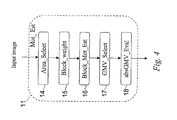
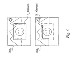
- the motion estimation phase 11 comprises preferably an "area select" phase 14 which selects two regions of the image Img n : a first region "B_Ground”, which represents the background of the scene reproduced by the image Img n , and a second region “F_Ground”, which represents the foreground (see Figure 5).
- the two regions may even be partially superposed and is not necessary that, taken together, they should cover the whole of the image.
- the image may be stabilized by correcting the unwanted motions (essentially due to vibrations of the video camera) after having estimated this motion by means of the oscillations that can be observed in the background of the image, i.e. by studying the motion of the background region.
- the stabilization is performed by correcting the undesired motion after having estimated it on the basis of the motions that can be observed in the foreground.
- the foreground is usually situated in a substantially central portion of the image, while the background is situated in the lateral and upper parts of the frame.
- the Area_Select phase could therefore select the B_Ground and F_Ground regions in a predetermined manner, for example, in the precise manner shown in Figure 5.
- the selection of the regions representing the foreground and the background could be made in a dynamic and adaptive manner.
- the Area_Select phase 14 could select the foreground and background regions, for example, in such a manner as to be exactly superposed on each other, i.e. turn them into a single region that will represent either the background or the foreground according to a user preselected stabilization strategy.
- the Mot_Est phase 11 also comprises a weight calculation phase 15 indicated in the figure as "Block_Weight".
- the B_Ground and F_Ground regions are subdivided into sub-blocks of pixels, to which we shall hereinafter refer also with the simpler term of blocks.
- These blocks may be, for example, small square blocks of size 8x8, 16x16, 32x32. It is, of course, also possible to make different choices as regards the size and the shape of the blocks. It will however be advantageous to make sure that the number of pixels in each block is small as compared with the size (the number of pixels) of the image.
- the two regions may be partially superposed, and some of the blocks could therefore form part of both the regions.
- the weight calculation phase 15 sets out to associate with each block of the foreground and background regions a respective weighting coefficient W that is correlated with some inhomogeneity measure and, for example, will become greater as the inhomogeneity of the block increases. For example, a block B1 that is wholly homogeneous will be assigned a weighting coefficient W1 equal to 1 (unity). A block B2 less homogeneous than block B1 will be assigned a weighting coefficient W2 greater than one.
- the inhomogeneity of a block represents the lack of uniformity existing between one or more parameters associated with the pixels of that same block and is therefore correlated with the spectral content of the block in the spatial frequency domain.
- the phase of evaluating the inhomogeneities serves to identify the blocks that, given their particular characteristics, can provide information about the global motion of the image Img n and possibly also serves to discard the blocks that are not very representative of the global motion of the image.
- the motion estimation of a substantially homogeneous block i.e. a block with only small inhomogeneity
- a block with high-frequency components can potentially provide very reliable information about the global motion of the image.
- the evaluation of the inhomogeneity of a block is performed by measuring the inhomogeneity of the luminance component Y of the pixels forming part of the block, since this is the component of the image for which the human eye has the greatest sensitivity.
- the estimation of the inhomogeneity could be carried out on images that have not yet been interpolated, possibly in Bayer CFA format, taking into consideration the green pixels.
- the reason for this choice is that in this format the green pixels are more numerous than the others and the green component is representative of the luminance information to within a good approximation.
- An inhomogeneity measure can be obtained, for example, by calculating the variance of the block or, more particularly, the variance of the luminance values of the pixels of the block. For example, given a block of size 16x16, the number of luminance values to be taken into consideration is 64. The greater the variance, the greater will be the inhomogeneity and therefore the weighting coefficient W to be associated with the block.
- the variance can be calculated as: where Y i,j is the luminance value of the pixel having the coordinates (i,j) in the block under consideration, m is the average luminance of the pixels of the block and N is the number of pixels in the block.
- the inhomogeneity is estimated by calculating the mean absolute difference MAD:
- the homogeneity is preferably also valued by calculating the "activation" A, which is a measure of the difference that exist between adjacent pixels both in the horizontal and in the vertical direction.
- A A hor + A vert
- a hor is the horizontal activation and is given by: while A vert is the vertical activation and is given by:
- the calculation of this measure does not call for a great computational effort.
- the activation measure values the presence of both horizontal and vertical edges or transitions more accurately than the two previously described measures and is therefore particularly suitable for characterizing the inhomogeneity of a block.
- a weighting coefficient W can be associated with each block.
- the table below illustrates an example of a possible association methodology: Activation W 0 ⁇ A ⁇ 10 1 10 ⁇ A ⁇ 500 2 500 ⁇ A ⁇ 1000 4 1000 ⁇ A ⁇ 2000 8 2000 ⁇ A ⁇ 4000 16 A ⁇ 4000 32
- the weighting coefficients W are assigned according to the range of values within which the calculated activation is comprised.
- the subsequent processing operations of the phase Mot_Est of estimating the global motion vector of the image Img n will take into consideration only the blocks that have an inhomogeneity greater than a predetermined value o or, more particularly, only blocks having a weighting coefficient W greater than a predetermined threshold value W th , for example, equal to 2.
- these blocks will henceforth be referred to as "above-threshold" blocks.
- the Mot_Est phase comprises - as shown in Figure 4 - a further phase 16, described as Block_Mot_Est, that associates with each block of the image Img n that has an above-threshold coefficient a respective block motion vector BMV that represents the translation motion that the block in question has undergone in passing from the previous image Img n-1 to the present image Img n .
- any appropriate method known to the state of the art may be used for determining a motion vector BMV to be associated with a given block.
- the conventional block motion estimation algorithm employed in the MPEG encoder of the video camera 1 may also be advantageously used in the method in accordance with the present invention.
- a phase 17, known as GMV_Select selects from among all the block motion vectors BMV the particular block motion vector BMV that is most representative of the global motion of the image Img n with respect to the previous image Img n-1 .
- the phase calculates a global motion vector B_GMV representative of the motion of the background region.
- the phase calculates a global motion vector F_GMV representative of the motion of the foreground region.
- the global motion vector B_GMV representative of the motion of the background region B_Ground will be calculated by constructing a bidimensional histogram of the block motion vectors BMV of the above-threshold blocks of the background region. In this histogram each block "votes" for its associated block vector BMV with the weighting coefficient W assigned to it.
- the phase selects from among the possible block motion vectors the one that has received the largest number of "votes", i.e. the one that produces a peak in the histogram.
- a two-dimensional histogram is not generally equivalent to two one-dimensional histograms of, respectively, the horizontal motion component and the vertical motion component. This is due to the fact that the correlation between the horizontal and vertical motion components is lost when two separate histograms are used. At times this loss will lead to an incorrect result.
- the motion vector F_GMV representative of the motions of the foreground region F_Ground is calculated in a similar manner.
- the GMV_Select phase assigns to the image Img n a global motion vector GMV[n,n-1] by selecting one of the two global motion vectors F_GMV and B_GMV calculated for the two regions as explained above.
- N 1 NB B_Ground TW B_Ground I B _Ground [ B _ GMV ]
- NB B_Ground is the number of above-threshold blocks in the background region B_Ground
- TW B _ Ground is the sum of all the values in the histogram (i.e. the sum of all the weighting coefficients associated with above-threshold blocks of the background region)
- I B _ Ground [ B _ GMV ] is the histogram value of the vector B_GMV, i.e. the peak value of the histogram.
- N 2 NB F_Ground TW F_Ground I F_Ground [ F_GMV ].
- a final phase 18, designated as absGMV Eval, of the motion estimation phase 11 calculates the absolute motion absGMV[n,ref] of the image Img n with respect to the image Img n-1 of the sequence as previously explained.
- unwanted motion estimation phase 12 estimates the unwanted motion from the absolute global motion vector absGMV[n, ref] of the image Img n .
- the two translation components in the horizontal and the vertical direction of the absolute global motion vector of the image Img n are taken into individual consideration in this phase, because there exists the possibility, for example, that estimated movement in the vertical direction is due to vibration (jiggling) and therefore unwanted, whereas the motion in the horizontal direction is due a panoramic shot (panning) and has therefore been purposely introduced by the operator.
- undesired motion having the characteristics of a random vibration will typically have a small amplitude and a zero mean value as compared with the reference image (because it rapidly changes direction).
- Purposely-introduced motion can attain large amplitudes and maintain the same direction for a long time.
- voluntary movements could even grow indefinitely and cause a situation of arithmetic overflow, i.e. grow to a value that exceeds the largest number that can be represented by the memory quantity reserved therefor.
- the unwanted motion estimation phase Unw_Mot_Est compares the horizontal component absGMV x [n,ref] of the absolute global motion vector absGMV[n,ref] estimated for the image Img n with a predetermined threshold value, which we shall henceforth refer to as the as the horizontal compensation threshold T hor / c om p .
- the horizontal component absGMV x [n,ref] has an amplitude smaller - the amplitude to be considered being that of the module - than the compensation threshold T hor / c om p , the horizontal component is associated with an unwanted motion, i.e. it is established that the horizontal motion component is due to an undesired motion. Otherwise the horizontal motion is associated with a purposely-introduced motion.
- a horizontal component associated with an undesired motion activates the subsequent unwanted motion compensation (or Unw_Mot_Comp) phase 13, which horizontally translates the image Img n in the direction opposite to that of the horizontal component and by a number of pixels equal to the amplitude of the horizontal component Img n , of the absolute global motion vector.
- Unw_Mot_Comp unwanted motion compensation
- the absolute motion vector is thus modified by making the amplitude of the horizontal component associated with a voluntary motion equal to the horizontal compensation threshold.
- its amplitude is fixed at a value that coincides with the compensation threshold.
- the horizontal motion component GMV x [n+1,n] is interpreted as an unwanted horizontal vibration, because its direction is contrary to the direction of the wanted motion, and the compensation phase 13 is therefore activated.
- this method of estimating the unwanted motion will also interpret the initial part of a voluntary motion as an unwanted motion (and will therefore correct/compensate it) until the compensation threshold is exceeded. Once this critical point has been passed, the remainder of the wanted motion is correctly interpreted and will not therefore be corrected/compensated. In any case, the erroneously corrected/compensated part of such a voluntary motion would be negligible, because these motions - by their very nature - are normally very extensive.
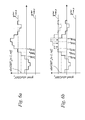
- Figures 6a and 6b illustrate the variations in the course of time of the horizontal components of the absolute motion vectors of an image sequence.
- Figure 6a shows the variations in time of the horizontal components of the absolute motion vectors that would be observed on the output side of the Mot_Est phase if the horizontal components having an amplitude greater than or equal to the compensation threshold were not to be modified.
- Figure 6b illustrates the time behaviour of the absolute motion vectors after they have been modified in phase 13, the Unw_Mot_Comp phase.
- the component having an amplitude greater than the threshold are modified in such a way as to have an amplitude equal to the threshold.
- the horizontal motion is interpreted as unwanted as far as image Img n-1 . But from image Img n onwards and as far as image Img n+3 the motion is interpreted as wanted. From image Img n+4 onwards, lastly, it is again interpreted as unwanted.
- the method in accordance with the present invention will be such as to provide for the compensation threshold - in this case horizontal - to be adaptively modified on the basis of its previous history.
- the horizontal compensation threshold will be raised, thus rendering the method more sensitive to unwanted horizontal motions. But when corrections/compensations predominate and wanted motion is only rarely detected, the threshold will be lowered.
- the value of the absolute global motion vector can be reduced at the end of a wanted motion (for example, it can be made equal to the compensation threshold) in order to render the stabilization more efficient in detecting unwanted motions having opposite directions.
- the unwanted motions are compensated/corrected in the unwanted motion compensation phase 13.
- the image Img n will be appropriately translated in the vertical/horizontal direction as previously described in order to compensate the unwanted motion.
- the translation phase will preferably be followed by an appropriate phase of re-dimensioning the image Img n, because the translation will cause a part of the image to be lost/discarded.
- An enlargement phase may also be introduced.
- the method of stabilization in accordance with the present invention has been found not only to provide a reliable and robust estimate of the movement of a sequence, but also to be capable of appropriately distinguishing unwanted motions that have to be stabilized from purposely introduced motions.
- the subdivision of the image into a region that represents the background and a region that represents the foreground makes it possible to obtain a motion estimation and an image stabilization that will be optimised in relation to the image content.
- the estimation of the motion vector representative of the motion of an entire image is obtained by using an inhomogeneity measure of image blocks suitable for evaluating the reliability of these blocks on the basis of their respective frequency contents.
- This measure is used for selecting one of multiplicity of block motion vectors as representative of the image motion.
- the inhomogeneity information serves not only to discard unreliable blocks, but is also used for weighting the reliability of the non-discarded blocks for the purposes of obtaining the global motion vector of the image.
- Another advantage derives from the fact that the method exploits the information of a large number of blocks, so that a possible block characterized by a considerable inhomogeneity (and therefore giving rise to a large weighting coefficient) but with a motion that is not representative of the image motion (due, for example, to the presence of moving objects in the scene) will have practically no influence on the image motion estimation if many other blocks provide correct information.
- the motion estimation method in accordance with the present invention need not necessarily be employed for this purpose.
- it could be alternatively and advantageously be used for estimating the motion of any kind of sequence of digital or digitalized photograms in alignment/registration techniques for photographic applications.
Priority Applications (2)
| Application Number | Priority Date | Filing Date | Title |
|---|---|---|---|
| EP02425402A EP1376471A1 (de) | 2002-06-19 | 2002-06-19 | Verfahren der Bewegungsschätzung zur Stabilisierung einer Bildsequenz |
| US10/462,090 US8325810B2 (en) | 2002-06-19 | 2003-06-13 | Motion estimation method and stabilization method for an image sequence |
Applications Claiming Priority (1)
| Application Number | Priority Date | Filing Date | Title |
|---|---|---|---|
| EP02425402A EP1376471A1 (de) | 2002-06-19 | 2002-06-19 | Verfahren der Bewegungsschätzung zur Stabilisierung einer Bildsequenz |
Publications (1)
| Publication Number | Publication Date |
|---|---|
| EP1376471A1 true EP1376471A1 (de) | 2004-01-02 |
Family
ID=29717015
Family Applications (1)
| Application Number | Title | Priority Date | Filing Date |
|---|---|---|---|
| EP02425402A Withdrawn EP1376471A1 (de) | 2002-06-19 | 2002-06-19 | Verfahren der Bewegungsschätzung zur Stabilisierung einer Bildsequenz |
Country Status (2)
| Country | Link |
|---|---|
| US (1) | US8325810B2 (de) |
| EP (1) | EP1376471A1 (de) |
Cited By (8)
| Publication number | Priority date | Publication date | Assignee | Title |
|---|---|---|---|---|
| EP1643762A1 (de) * | 2004-10-01 | 2006-04-05 | Nikon Corporation | Gerät zum Verarbeiten beweglicher Bilder und Verfahren zum Ausführen verschiedener Verarbeitungen bei Bereichen beweglicher und unbeweglicher Objeke |
| WO2008057841A1 (en) * | 2006-11-09 | 2008-05-15 | Intel Corporation | Digital video stabilization based on robust dominant motion estimation |
| EP2143003A1 (de) * | 2007-04-27 | 2010-01-13 | Coupons, Inc. | Kopierschutz für kupons |
| CN102238332A (zh) * | 2010-04-28 | 2011-11-09 | 索尼公司 | 图像处理装置、图像处理方法、成像装置和程序 |
| FR2969352A1 (fr) * | 2010-12-20 | 2012-06-22 | St Ericsson Sa | Procede de realisation d'une image panoramique et appareil de mise en œuvre. |
| US8531504B2 (en) | 2010-06-11 | 2013-09-10 | Intel Corporation | System and method for 3D video stabilization by fusing orientation sensor readings and image alignment estimates |
| US20160112717A1 (en) * | 2007-01-26 | 2016-04-21 | Telefonaktiebolaget Lm Ericsson (Publ) | Motion estimation for uncovered frame regions |
| CN110378930A (zh) * | 2019-09-11 | 2019-10-25 | 湖南德雅坤创科技有限公司 | 运动目标提取方法、装置和电子设备及可读存储介质 |
Families Citing this family (33)
| Publication number | Priority date | Publication date | Assignee | Title |
|---|---|---|---|---|
| US8229549B2 (en) * | 2004-07-09 | 2012-07-24 | Tyco Healthcare Group Lp | Surgical imaging device |
| KR100579493B1 (ko) * | 2003-06-16 | 2006-05-15 | 삼성전자주식회사 | 움직임 벡터 생성 장치 및 방법 |
| KR100584597B1 (ko) * | 2004-05-10 | 2006-05-30 | 삼성전자주식회사 | 적응적 가중치를 적용한 움직임 추정 방법 및 그를 적용한프레임 레이트 변환 장치 |
| KR20050119285A (ko) * | 2004-06-16 | 2005-12-21 | 삼성전자주식회사 | 하이브리드 블록기반 움직임 추정장치 및 그 방법 |
| US7705884B2 (en) * | 2004-07-21 | 2010-04-27 | Zoran Corporation | Processing of video data to compensate for unintended camera motion between acquired image frames |
| US7684628B2 (en) * | 2004-08-12 | 2010-03-23 | Industrial Technology Research Institute | System and method for non-iterative global motion estimation |
| FR2875091B1 (fr) * | 2004-09-08 | 2006-11-24 | Citilog Sa | Procede et dispositif pour stabiliser les images donnees par une camera video |
| US7649549B2 (en) * | 2004-09-27 | 2010-01-19 | Texas Instruments Incorporated | Motion stabilization in video frames using motion vectors and reliability blocks |
| US20060120615A1 (en) * | 2004-12-06 | 2006-06-08 | Huiqiong Wang | Frame compensation for moving imaging devices |
| US7489341B2 (en) * | 2005-01-18 | 2009-02-10 | Primax Electronics Ltd. | Method to stabilize digital video motion |
| DE102005025634A1 (de) * | 2005-06-03 | 2006-12-07 | Micronas Gmbh | Verfahren und Vorrichtung zur Ermittlung von Bewegungsvektoren |
| US9258519B2 (en) * | 2005-09-27 | 2016-02-09 | Qualcomm Incorporated | Encoder assisted frame rate up conversion using various motion models |
| US20070076982A1 (en) * | 2005-09-30 | 2007-04-05 | Petrescu Doina I | System and method for video stabilization |
| KR100775104B1 (ko) * | 2006-02-27 | 2007-11-08 | 삼성전자주식회사 | 영상 신호의 떨림 보정 장치와 그를 포함하는 영상 시스템및 그 방법 |
| US8130845B2 (en) * | 2006-11-02 | 2012-03-06 | Seiko Epson Corporation | Method and apparatus for estimating and compensating for jitter in digital video |
| JP4412323B2 (ja) * | 2006-12-28 | 2010-02-10 | 株式会社日立製作所 | 映像処理装置及び映像表示装置 |
| TWI367026B (en) * | 2007-03-28 | 2012-06-21 | Quanta Comp Inc | Method and apparatus for image stabilization |
| KR101392732B1 (ko) * | 2007-08-20 | 2014-05-08 | 삼성전자주식회사 | 손떨림에 의한 움직임 추정 장치 및 방법, 그를 이용한영상 촬상 장치 |
| JP5045320B2 (ja) * | 2007-09-05 | 2012-10-10 | ソニー株式会社 | 画像処理装置、および画像処理方法、並びにコンピュータ・プログラム |
| JP4544334B2 (ja) * | 2008-04-15 | 2010-09-15 | ソニー株式会社 | 画像処理装置および画像処理方法 |
| EP2494781A1 (de) | 2009-10-29 | 2012-09-05 | Vestel Elektronik Sanayi ve Ticaret A.S. | Verfahren und vorrichtung zur verarbeitung einer videosequenz |
| CN102065278A (zh) * | 2009-11-12 | 2011-05-18 | 鸿富锦精密工业(深圳)有限公司 | 电子设备及其监控方法 |
| US8896715B2 (en) | 2010-02-11 | 2014-11-25 | Microsoft Corporation | Generic platform video image stabilization |
| US9824426B2 (en) | 2011-08-01 | 2017-11-21 | Microsoft Technology Licensing, Llc | Reduced latency video stabilization |
| TWI459810B (zh) * | 2011-11-22 | 2014-11-01 | Altek Corp | 影像處理裝置及其處理方法 |
| US9510018B2 (en) * | 2011-11-23 | 2016-11-29 | Luca Rossato | Signal analysis and generation of transient information |
| FR2985065B1 (fr) * | 2011-12-21 | 2014-01-10 | Univ Paris Curie | Procede d'estimation de flot optique a partir d'un capteur asynchrone de lumiere |
| US10136063B2 (en) | 2013-07-12 | 2018-11-20 | Hanwha Aerospace Co., Ltd | Image stabilizing method and apparatus |
| KR102069269B1 (ko) * | 2014-01-21 | 2020-01-22 | 한화테크윈 주식회사 | 영상 안정화 장치 및 방법 |
| US10949985B2 (en) | 2016-06-02 | 2021-03-16 | Stc.Unm | System and methods for parallel processing motion estimation of digital videos |
| CN106651918B (zh) * | 2017-02-16 | 2020-01-31 | 国网上海市电力公司 | 抖动背景下的前景提取方法 |
| CN107396111B (zh) * | 2017-07-13 | 2020-07-14 | 河北中科恒运软件科技股份有限公司 | 介导现实中自动视频插帧补偿方法及系统 |
| JP6545229B2 (ja) * | 2017-08-23 | 2019-07-17 | キヤノン株式会社 | 画像処理装置、撮像装置、画像処理装置の制御方法およびプログラム |
Family Cites Families (22)
| Publication number | Priority date | Publication date | Assignee | Title |
|---|---|---|---|---|
| DE3634414C2 (de) * | 1986-10-09 | 1994-12-08 | Thomson Brandt Gmbh | Fernsehkamera mit einem Target |
| US5012270A (en) * | 1988-03-10 | 1991-04-30 | Canon Kabushiki Kaisha | Image shake detecting device |
| US5107293A (en) * | 1988-09-09 | 1992-04-21 | Canon Kabushiki Kaisha | Automatic image stabilization device |
| US5109249A (en) * | 1989-10-12 | 1992-04-28 | Ricoh Company, Ltd. | Camera with a function of preventing a hand moving blur |
| JP2600504B2 (ja) * | 1991-01-25 | 1997-04-16 | 日本ビクター株式会社 | 動きベクトル検出回路 |
| US5469210A (en) * | 1991-03-01 | 1995-11-21 | Canon Kabushiki Kaisha | Image pickup apparatus with control for output of non-vibrating images |
| JP2677312B2 (ja) * | 1991-03-11 | 1997-11-17 | 工業技術院長 | カメラワーク検出方法 |
| US5331414A (en) * | 1991-12-23 | 1994-07-19 | Intel Corporation | Method and apparatus for encoding a digital motion video signal using pyramid specific filtering |
| US5544284A (en) * | 1992-02-11 | 1996-08-06 | Eastman Kodak Company | Sequential product code quantization of digital color image |
| US5311305A (en) * | 1992-06-30 | 1994-05-10 | At&T Bell Laboratories | Technique for edge/corner detection/tracking in image frames |
| DE69428838T2 (de) * | 1993-06-29 | 2002-07-18 | Sanyo Electric Co | Videokamera mit elektronischer Bildstabilisierung und Erzeugung von Additionsdaten |
| EP0697788A3 (de) * | 1994-08-19 | 1997-03-26 | Eastman Kodak Co | Adaptive und für globale Bewegung kompensierte Aufhebung des Zeilensprungverfahrens von aufeinenanderfolgenden Videobildern mit Nachbearbeitung |
| US5835138A (en) | 1995-08-30 | 1998-11-10 | Sony Corporation | Image signal processing apparatus and recording/reproducing apparatus |
| WO1999012355A1 (de) | 1997-08-29 | 1999-03-11 | Siemens Aktiengesellschaft | Verfahren zum komprimieren von bildinformationen |
| US6748158B1 (en) * | 1999-02-01 | 2004-06-08 | Grass Valley (U.S.) Inc. | Method for classifying and searching video databases based on 3-D camera motion |
| US6628711B1 (en) * | 1999-07-02 | 2003-09-30 | Motorola, Inc. | Method and apparatus for compensating for jitter in a digital video image |
| US6809758B1 (en) | 1999-12-29 | 2004-10-26 | Eastman Kodak Company | Automated stabilization method for digital image sequences |
| EP1139669A1 (de) | 2000-03-28 | 2001-10-04 | STMicroelectronics S.r.l. | Koprozessor zur bewegungsschätzung in codierern für digitalisierte videosequenzen |
| JP3679988B2 (ja) * | 2000-09-28 | 2005-08-03 | 株式会社東芝 | 画像処理装置及び画像処理方法 |
| US20020039138A1 (en) * | 2000-09-29 | 2002-04-04 | Edelson Steven D. | Method and apparatus for automatically adjusting video panning and zoom rates |
| US6987530B2 (en) * | 2001-05-29 | 2006-01-17 | Hewlett-Packard Development Company, L.P. | Method for reducing motion blur in a digital image |
| US7227896B2 (en) * | 2001-10-04 | 2007-06-05 | Sharp Laboratories Of America, Inc. | Method and apparatus for global motion estimation |
-
2002
- 2002-06-19 EP EP02425402A patent/EP1376471A1/de not_active Withdrawn
-
2003
- 2003-06-13 US US10/462,090 patent/US8325810B2/en active Active
Non-Patent Citations (1)
| Title |
|---|
| VELLA F ET AL: "Robust digital image stabilization algorithm using block motion vectors", 2002 DIGEST OF TECHNICAL PAPERS. INTERNATIONAL CONFERENCE ON CONSUMER ELECTRONICS, LOS ANGELES, CA, USA, 18-20 JUNE 2002, 2002, Piscataway, NJ, USA, IEEE, USA, pages 234 - 235, XP002215391, ISBN: 0-7803-7300-6 * |
Cited By (17)
| Publication number | Priority date | Publication date | Assignee | Title |
|---|---|---|---|---|
| US8514293B2 (en) | 2004-10-01 | 2013-08-20 | Nikon Corporation | Moving image processing device and method for performing different image processings to moving object region and still object region |
| EP1643762A1 (de) * | 2004-10-01 | 2006-04-05 | Nikon Corporation | Gerät zum Verarbeiten beweglicher Bilder und Verfahren zum Ausführen verschiedener Verarbeitungen bei Bereichen beweglicher und unbeweglicher Objeke |
| WO2008057841A1 (en) * | 2006-11-09 | 2008-05-15 | Intel Corporation | Digital video stabilization based on robust dominant motion estimation |
| US9860554B2 (en) * | 2007-01-26 | 2018-01-02 | Telefonaktiebolaget Lm Ericsson (Publ) | Motion estimation for uncovered frame regions |
| US20160112717A1 (en) * | 2007-01-26 | 2016-04-21 | Telefonaktiebolaget Lm Ericsson (Publ) | Motion estimation for uncovered frame regions |
| US8000496B2 (en) | 2007-04-27 | 2011-08-16 | Coupons.Com Incorporated | Coupon copy protection |
| US8559667B2 (en) | 2007-04-27 | 2013-10-15 | Coupons.Com Incorporated | Coupon copy protection |
| EP2143003A4 (de) * | 2007-04-27 | 2011-05-25 | Coupons Inc | Kopierschutz für kupons |
| US9424585B2 (en) | 2007-04-27 | 2016-08-23 | Quotient Technology, Inc. | Coupon copy protection |
| US9576298B2 (en) | 2007-04-27 | 2017-02-21 | Quotient Technology Inc. | Coupon copy protection |
| EP2143003A1 (de) * | 2007-04-27 | 2010-01-13 | Coupons, Inc. | Kopierschutz für kupons |
| CN102238332A (zh) * | 2010-04-28 | 2011-11-09 | 索尼公司 | 图像处理装置、图像处理方法、成像装置和程序 |
| US8531504B2 (en) | 2010-06-11 | 2013-09-10 | Intel Corporation | System and method for 3D video stabilization by fusing orientation sensor readings and image alignment estimates |
| FR2969352A1 (fr) * | 2010-12-20 | 2012-06-22 | St Ericsson Sa | Procede de realisation d'une image panoramique et appareil de mise en œuvre. |
| WO2012084883A1 (en) * | 2010-12-20 | 2012-06-28 | St-Ericsson Sa | Method for producing a panoramic image and implementation apparatus |
| CN110378930A (zh) * | 2019-09-11 | 2019-10-25 | 湖南德雅坤创科技有限公司 | 运动目标提取方法、装置和电子设备及可读存储介质 |
| CN110378930B (zh) * | 2019-09-11 | 2020-01-31 | 湖南德雅坤创科技有限公司 | 运动目标提取方法、装置和电子设备及可读存储介质 |
Also Published As
| Publication number | Publication date |
|---|---|
| US8325810B2 (en) | 2012-12-04 |
| US20040027454A1 (en) | 2004-02-12 |
Similar Documents
| Publication | Publication Date | Title |
|---|---|---|
| EP1376471A1 (de) | Verfahren der Bewegungsschätzung zur Stabilisierung einer Bildsequenz | |
| US7852375B2 (en) | Method of stabilizing an image sequence | |
| US7773115B2 (en) | Method and system for deblurring digital camera images using reference image and motion estimation | |
| JP5908511B2 (ja) | ブロックベースの画像安定化 | |
| US7903156B2 (en) | Image processing device, image processing method, computer program, recording medium storing the computer program, frame-to-frame motion computing method, and image processing method | |
| US7755667B2 (en) | Image sequence stabilization method and camera having dual path image sequence stabilization | |
| EP0629083B1 (de) | Abtastungsumwandler von Zeilensprung in ohne Zeilensprung mit einer doppelten Glättungsfunktion und Verfahren dafür | |
| US7369181B2 (en) | Method of removing noise from digital moving picture data | |
| US8300120B2 (en) | Image processing apparatus and method of processing image for reducing noise of the image | |
| US8179446B2 (en) | Video stabilization and reduction of rolling shutter distortion | |
| KR101442153B1 (ko) | 저조도 영상 처리 방법 및 시스템 | |
| JP5052301B2 (ja) | 画像処理装置、画像処理方法 | |
| US20120162454A1 (en) | Digital image stabilization device and method | |
| US7734110B2 (en) | Method for filtering the noise of a digital image sequence | |
| US20040218073A1 (en) | Color filter array interpolation | |
| KR100745386B1 (ko) | 화상 신호 처리 장치, 화상 신호 처리 방법, 학습 장치,학습 방법 및 기록 매체 | |
| KR101225056B1 (ko) | 이미지 센서 노이즈 저감 장치 및 방법 | |
| US20040179108A1 (en) | Adaptive low-light image processing | |
| CN102595027A (zh) | 图像处理设备和图像处理方法 | |
| WO2007085004A2 (en) | Hand jitter reduction for compensating for linear displacement | |
| US7489822B2 (en) | Image processing apparatus and method for detecting a direction of an edge in the vicinity of a pixel of interest and generating all color signals for each pixel by interpolation using color signals of a pixel of interest and its neighbor pixels, and a recording medium having a program recorded thereon for causing the apparatus to perform the method | |
| JP2007323635A (ja) | ビデオ・イメージの再帰的フィルタリング | |
| JPH0846934A (ja) | ディジタル画像信号の処理装置 | |
| JP2917988B1 (ja) | 動画像符号化装置のプレフィルタ | |
| EP1636987A1 (de) | Räumliche signalumsetzung |
Legal Events
| Date | Code | Title | Description |
|---|---|---|---|
| PUAI | Public reference made under article 153(3) epc to a published international application that has entered the european phase |
Free format text: ORIGINAL CODE: 0009012 |
|
| AK | Designated contracting states |
Kind code of ref document: A1 Designated state(s): AT BE CH CY DE DK ES FI FR GB GR IE IT LI LU MC NL PT SE TR |
|
| AX | Request for extension of the european patent |
Extension state: AL LT LV MK RO SI |
|
| 17P | Request for examination filed |
Effective date: 20040622 |
|
| AKX | Designation fees paid |
Designated state(s): DE FR GB IT |
|
| 17Q | First examination report despatched |
Effective date: 20080521 |
|
| RAP1 | Party data changed (applicant data changed or rights of an application transferred) |
Owner name: STMICROELECTRONICS SRL |
|
| RAP1 | Party data changed (applicant data changed or rights of an application transferred) |
Owner name: STMICROELECTRONICS SRL |
|
| STAA | Information on the status of an ep patent application or granted ep patent |
Free format text: STATUS: THE APPLICATION IS DEEMED TO BE WITHDRAWN |
|
| 18D | Application deemed to be withdrawn |
Effective date: 20130103 |