EP1375957B1 - Amortisseur hydraulique de fin de course autonome - Google Patents
Amortisseur hydraulique de fin de course autonome Download PDFInfo
- Publication number
- EP1375957B1 EP1375957B1 EP03253893A EP03253893A EP1375957B1 EP 1375957 B1 EP1375957 B1 EP 1375957B1 EP 03253893 A EP03253893 A EP 03253893A EP 03253893 A EP03253893 A EP 03253893A EP 1375957 B1 EP1375957 B1 EP 1375957B1
- Authority
- EP
- European Patent Office
- Prior art keywords
- rod
- piston
- housing
- chamber
- cylinder
- Prior art date
- Legal status (The legal status is an assumption and is not a legal conclusion. Google has not performed a legal analysis and makes no representation as to the accuracy of the status listed.)
- Expired - Lifetime
Links
Images

Classifications
-
- F—MECHANICAL ENGINEERING; LIGHTING; HEATING; WEAPONS; BLASTING
- F15—FLUID-PRESSURE ACTUATORS; HYDRAULICS OR PNEUMATICS IN GENERAL
- F15B—SYSTEMS ACTING BY MEANS OF FLUIDS IN GENERAL; FLUID-PRESSURE ACTUATORS, e.g. SERVOMOTORS; DETAILS OF FLUID-PRESSURE SYSTEMS, NOT OTHERWISE PROVIDED FOR
- F15B15/00—Fluid-actuated devices for displacing a member from one position to another; Gearing associated therewith
- F15B15/20—Other details, e.g. assembly with regulating devices
- F15B15/22—Other details, e.g. assembly with regulating devices for accelerating or decelerating the stroke
- F15B15/227—Other details, e.g. assembly with regulating devices for accelerating or decelerating the stroke having an auxiliary cushioning piston within the main piston or the cylinder end face
-
- F—MECHANICAL ENGINEERING; LIGHTING; HEATING; WEAPONS; BLASTING
- F16—ENGINEERING ELEMENTS AND UNITS; GENERAL MEASURES FOR PRODUCING AND MAINTAINING EFFECTIVE FUNCTIONING OF MACHINES OR INSTALLATIONS; THERMAL INSULATION IN GENERAL
- F16F—SPRINGS; SHOCK-ABSORBERS; MEANS FOR DAMPING VIBRATION
- F16F9/00—Springs, vibration-dampers, shock-absorbers, or similarly-constructed movement-dampers using a fluid or the equivalent as damping medium
- F16F9/32—Details
- F16F9/48—Arrangements for providing different damping effects at different parts of the stroke
- F16F9/49—Stops limiting fluid passage, e.g. hydraulic stops or elastomeric elements inside the cylinder which contribute to changes in fluid damping
Definitions
- the present invention relates generally to hydraulic snubbers, and, more particularly, to an improved self-contained end-of-stroke hydraulic snubber that is intended to decelerate and cushion movement of an actuator rod at either end of its stroke.
- Hydraulic actuators are frequently fitted with separate snubbing mechanisms to decelerate and reduce the impact of the piston hitting the end of the cylinder at either end of its stroke.
- separate hydraulic snubber assemblies are frequently added to decelerate and cushion both ends of the actuator rod movement.
- Hydraulic actuators used in flight simulator motion systems have been using end-of-stroke cushions integrated into the hydraulic cylinder for many years.
- electrical actuators began to be used in motion systems in the early 1990's, there was a need to incorporate snubbers to perform this cushioning function.
- a hydraulic actuator it is straight-forward to incorporate snubbing.
- electro-mechanical actuator however, snubbing requires a separate add-on device for that purpose.
- One approach has been to use separate snubber cylinders packaged either inside or outside of the actuator at each end.
- JPA 09210018A discloses a stroke snubbing device according to the preamble of claim 1.
- DE 3245732 shows a stroke snubbing device with a housing, a movable member, a variable volume chamber and a lost-motion mechanism.
- the present invention broadly provides (e.g., in Fig. 1) an improved single self-contained bidirectional end-of-stroke hydraulic snubbing device that is operative to decelerate and cushion movement of an actuator rod at either end of its stroke.
- a bi-directional end-of stroke snubbing device comprising: a housing; a rod movable relative to said housing; a single fluid-filled variable-volume annular chamber communicating with a fluid sump through an orifice; said chamber being defined between at least one piston and a cylinder, and a lost-motion mechanism for selectively causing a reduction of the volume of said chamber by motion of said rod approaching either end of its stroke; whereby said mechanism will force fluid from said chamber through said orifice to decelerate movement of said rod relative to said housing proximate either end of its stroke, characterized by said piston and said cylinder being concentric with said rod.
- the chamber may be defined between a cylinder and two pistons, as shown in Fig. 2.
- the fluid sump may include an accumulator, which may be pressurized if desired.
- the lost-motion mechanism may include a first abutment member mounted on the member to engage one portion of the wall of the chamber, and a second abutment member mounted on the member to engage another portion of the chamber wall.
- the general object of this invention is to provide an improved end-of-stroke snubbing device.
- Another object is to provide a single snubbing device which may be mounted on an electro-mechanical actuator, and which may selectively and controllably decelerate and cushion movement of the actuator rod proximate either end of its stroke.
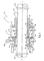
- the first form of the improved end-of-stroke snubbing device is generally indicated at 20.
- This device is shown as broadly including a housing, a fragmentary portion of which is generally indicated at 21; an actuator rod 22 movable relative to the housing; a single fluid-filled variable-volume chamber 23; a fluid sump 24; and a lost-motion mechanism 25.
- rod 22 is shown as being a horizontally-elongated cylindrical member which is mounted for controlled horizontal movement along its axis x-x.
- the rod has a pair of axially-spaced annular stops or shoulder members extending radially outwardly therefrom.
- the left shoulder member is indicated at 26, and the right shoulder member is indicated at 28.
- Members 26 and 28 may be formed integrally with rod 22, or may be formed separately and subsequently attached to the rod, as desired.
- Rod 22 is thus mounted for horizontal reciprocating movement relative to housing 21.
- the snubber includes the single fluid-filled variable-volume chamber 23, which is defined between a rightward inverted reversed C-shaped cylinder member 29 and a leftward piston member 30 received therein. Members 29 and 30 are mounted for selective axial movement relative to one another to vary the volume of intermediate chamber 23, as described infra .
- Cylinder member 29 is shown as having an annular leftwardly-opening cup-shaped transverse cross-section. More particularly, this cross-section is sequentially bounded by an outwardly-facing horizontal cylindrical surface 31, a leftwardly-facing annular vertical surface 32, and inwardly-facing cylindrical surface 33, a leftwardly-facing annular vertical surface 34, an outwardly-facing horizontal cylindrical surface 35, a leftwardly-facing annular vertical surface 36 substantially coplanar with surface 32, an inwardly-facing horizontal cylindrical surface 38, and a rightwardly-facing annular vertical surface 39, an outwardly-facing horizontal cylindrical surface 40, and a rightwardly-facing annular vertical surface 41 extending radially outwardly therefrom to join the right end of surface 31.
- Piston member 30 is shown as being a specially-configured annular member that is sequentially bounded by a leftwardly-facing annular vertical surface 42, an outwardly-facing horizontal cylindrical surface 43, a leftwardly-facing annular vertical 44, an outwardly-facing horizontal cylindrical surface 45, a rightwardly-facing annular vertical surface 46, an inwardly-facing horizontal cylindrical surface 48, a rightwardly-facing annular vertical surface 49, and an inwardly-facing horizontal cylindrical surface 50 extending leftwardly therefrom to join the inner margin of left end face 42.
- Piston member surface 43 is arranged in closely-spaced facing relation to an inwardly-facing horizontal cylindrical surface 51 of the housing, and the sliding joint therebetween is sealed by means of an O-ring 52.
- Piston member surface 45 is arranged in closely-spaced facing relation to surface 33, and the sliding joint therebetween is sealed by an O-ring 53.
- Piston member surface 48 is arranged in closely-spaced facing relation to surface 35, and the sliding joint therebetween is sealed by a means of an O-ring 54.
- Cylinder member surface 31 is arranged in spaced facing relation to an inwardly-facing horizontal cylindrical surface 55 of the housing.
- Cylinder member surface 40 is arranged in closely-spaced facing relation to housing surface 56, and the joint therebetween is sealed by an O-ring 58.
- the housing is shown, in pertinent part, as having a rightward portion 59 which extends radially inwardly toward the member, an outer portion 60, a leftward portion 61, and an inner portion 62 which extends rightwardly from the inner margin of leftward portion 61.
- the leftwardly-facing annular vertical surface 63 of housing rightward portion 59 serves as an abutment stop to limit rightward movement of cylinder member 29.
- the rightwardly-facing annular vertical surface 64 of housing inner portion 62 serves as an abutment stop to limit leftward movement of member 30.
- Members 29 and 30 define a fluid-filled variable-volume chamber 23 therebetween, which communicates via three axially-spaced orifices, severally indicated at 65, with a sump chamber 66. This sump chamber in turn communicates with the pressurized accumulator 68.
- Snubber 20 does not interfere with normal movement of the rod-like member 22 relative to the housing intermediate the ends of its stroke.
- the annular vertical right face of left rod abutment 26 would first engage piston surface 42. Thereafter, continued rightward movement of rod 22 would cause piston member 30 to move rightwardly within cylinder member 29, thereby forcing fluid in chamber 23 to pass through orifices 65, 65, 65 into sump chamber 66, and from there into accumulator 68.
- piston member 30 will sequentially occlude the three spaced orifices, thereby progressively decreasing the orifice area as the piston moves rightwardly within the cylinder. This action will therefore decelerate and cushion such rightward movement of the rod relative to the housing.
- FIG. 2 A second form of the inventive snubber is shown in Fig. 2.
- the snubber is generally indicated at 70.
- the snubber is again shown as having a rod 22 provided with axially-spaced bosses or abutment stops 26, 28 respectively.
- the housing is generally indicated at 71.
- the housing has a rightward portion 72 which extends radially inwardly toward the rod, an intermediate portion 73, and a leftward portion 74.
- the mechanism includes a leftward piston member 75 and a rightward piston member 76. These two piston members are mounted for movement within a cylinder-like member defined by the housing.
- Left piston member 75 is shown as being a specially-configured member somewhat analogous to member 30 in the first embodiment. More particularly, left piston member 75 is shown as being sequentially bounded by a leftwardly-facing annular vertical surface 78, an outwardly-facing horizontal cylindrical surface 79, a leftwardly-facing annular vertical surface 80, an outwardly-facing horizontal cylindrical surface 81, a rightwardly-facing annular vertical surface 82, an inwardly-facing horizontal cylindrical surface 83, a rightwardly-facing annular vertical surface 84, and an inwardly-facing horizontal cylindrical surface 85 continuing leftwardly therefrom to rejoin the inner margin of left end face 78.
- Right piston member 76 is shown as being sequentially bounded by an annular vertical left face 86, an outwardly-facing horizontal cylindrical surface 88, a leftwardly-facing annular vertical surface 89, and outwardly-facing horizontal cylindrical surface 90, a rightwardly-facing annular vertical surface 91, an outwardly-facing horizontal cylindrical surface 92, an annular vertical right end face 93, and an inwardly-facing horizontal cylindrical surface 94 continuing leftwardly therefrom to join the inner margin of left end face 86.
- a portion of right piston surface 88 is adapted to be arranged in closely-spaced facing relation to surface 83, and the sliding joint therebetween is sealed by means of an O-ring 95.
- An O-ring 96 seals the sliding joint between left piston surface 81 and the inwardly-facing surface 98 of the housing.
- Another O-ring 99 is operatively raised to seal the sliding joint between left piston surface 79 and the inwardly-facing surface 100 of the housing.
- Still another O-ring 103 is arranged to seal the sliding joint between right piston surface 90 and housing surface 98.
- the housing contains a passageway 105 which communicates a small fluid sump chamber 106 with a pressurized accumulator 108.
- the snubber shown in Fig. 2 while structurally different, operates functionally in substantially in the same manner as the device shown in Fig. 1.
- the snubber does not interfere with normal motion of the rod intermediate the ends of its stroke.
- the present invention provides an improved self-contained end-of-stroke snubbing device which is operational bidirectionally (i.e. , regardless of the direction the rod moves relative to the housing).
- one of the members may be configured as a piston movable relative to the other, which is configured as cylinder, as shown in Fig. 1.
- the housing may define a cylinder, and both of the members may be configured as pistons movable within that cylinder, as shown in Fig. 2.
- the pressurized fluid provided by accumulators 68, 108 biases the piston-cylinder and piston-piston members, respectively, to move apart from one another.
- a return spring could perform this function.
- the materials of construction and dimensions are not considered to be particularly critical, and may be readily changed or modified as desired.
- the general shape and configuration of the various parts are not limited to the particular forms shown. Also, other types of lost-motion connections may be substituted therefore.
Claims (7)
- Dispositif amortisseur de fin de course bidirectionnel (20), comprenant : un boîtier (21) ; une tige (22) mobile par rapport audit boîtier (21) ; une chambre annulaire unique (23, 109) à volume variable et remplie de fluide, en communication avec une bâche à fluide (24) via un orifice (65, 110) ; ladite chambre (23, 109) étant définie entre au moins un piston (30, 75, 76) et un cylindre (29, 73), et un mécanisme à course morte (25) pour provoquer sélectivement une réduction du volume de ladite chambre (23, 109) par un mouvement de ladite tige (22) qui s'approche d'une fin ou de l'autre de sa course ; grâce à quoi ledit mécanisme (25) va forcer le fluide hors de ladite chambre (23, 109) via ledit orifice (65, 110) pour décélérer le mouvement de ladite tige (22) par rapport audit boîtier (21) à proximité d'une fin ou de l'autre de sa course, caractérisé en ce que ledit piston (30, 75, 76) et ledit cylindre (29, 73) sont concentriques avec ladite tige.
- Dispositif (20) selon la revendication 1, dans lequel ladite chambre (109) est définie entre un cylindre (73) et deux pistons (75, 76).
- Dispositif (20) selon la revendication 1, dans lequel ladite bâche est un accumulateur (68).
- Dispositif (20) selon la revendication 3, dans lequel ledit accumulateur (68) est mis sous pression.
- Dispositif (20) selon la revendication 1, dans lequel ledit mécanisme inclut une première surface de butée (26) montée sur ladite tige (22) pour engager l'un des éléments parmi ledit piston (30, 75) et ledit cylindre (29, 73).
- Dispositif (20) selon la revendication 1, dans lequel ledit mécanisme inclut une seconde surface de butée (28) montée sur ladite tige (22) pour engager un autre des éléments parmi ledit piston (76) et ledit cylindre (29).
- Dispositif (20) selon la revendication 1, dans lequel la taille dudit orifice diminue alors que le volume de ladite chambre diminue.
Applications Claiming Priority (2)
| Application Number | Priority Date | Filing Date | Title |
|---|---|---|---|
| US10/184,700 US6763920B2 (en) | 2002-06-28 | 2002-06-28 | Self-contained bidirectional end-of-stroke hydraulic snubber |
| US184700 | 2002-06-28 |
Publications (2)
| Publication Number | Publication Date |
|---|---|
| EP1375957A1 EP1375957A1 (fr) | 2004-01-02 |
| EP1375957B1 true EP1375957B1 (fr) | 2006-01-04 |
Family
ID=29717973
Family Applications (1)
| Application Number | Title | Priority Date | Filing Date |
|---|---|---|---|
| EP03253893A Expired - Lifetime EP1375957B1 (fr) | 2002-06-28 | 2003-06-19 | Amortisseur hydraulique de fin de course autonome |
Country Status (5)
| Country | Link |
|---|---|
| US (1) | US6763920B2 (fr) |
| EP (1) | EP1375957B1 (fr) |
| JP (1) | JP4166636B2 (fr) |
| CA (1) | CA2433827C (fr) |
| DE (1) | DE60303092T2 (fr) |
Families Citing this family (15)
| Publication number | Priority date | Publication date | Assignee | Title |
|---|---|---|---|---|
| DE102004021558A1 (de) * | 2004-05-03 | 2005-12-08 | Daimlerchrysler Ag | Schwingungsdämpfer mit Zuganschlag |
| FR2885192A1 (fr) * | 2005-04-29 | 2006-11-03 | Renault Sas | Systeme de butee hydraulique d'un vehicule automobile |
| FR2894303B1 (fr) * | 2005-12-02 | 2010-09-03 | Pommier S C E B P | Verin hydraulique a amortissement |
| JP5100150B2 (ja) | 2006-03-02 | 2012-12-19 | 株式会社コガネイ | ショックアブソーバ |
| JP4971828B2 (ja) * | 2006-03-02 | 2012-07-11 | 株式会社コガネイ | ショックアブソーバ |
| US20090173402A1 (en) * | 2007-12-05 | 2009-07-09 | Pacific Scientific Company | Snubber valve |
| DE102010017204A1 (de) * | 2010-06-02 | 2012-01-05 | Amazonen-Werke H. Dreyer Gmbh & Co. Kg | Landwirtschaftliche Verteilmaschine |
| FR2975744B1 (fr) * | 2011-05-25 | 2013-11-22 | Peugeot Citroen Automobiles Sa | Dispositif de deplacement commande en translation d'une fourchette de passage de vitesse pour boite de vitesses de vehicule automobile |
| FR2990735B1 (fr) * | 2012-05-16 | 2015-01-16 | Peugeot Citroen Automobiles Sa | Amortisseur hydraulique comprenant une butee de fin de course comportant un piston |
| DE102012107197A1 (de) * | 2012-08-06 | 2014-02-06 | Still Gmbh | Hydraulikzylinder mit Endlagendämpfung |
| US9091320B1 (en) | 2014-01-08 | 2015-07-28 | Thyssenkrupp Bilstein Of America, Inc. | Multi-stage shock absorber |
| FR3049231B1 (fr) * | 2016-03-24 | 2019-06-07 | Peugeot Citroen Automobiles Sa | Systeme de suspension hydraulique d'un vehicule |
| DE102018201276A1 (de) * | 2018-01-29 | 2019-08-14 | Volkswagen Aktiengesellschaft | Schwingungsdämpfer mit hydraulischem Zuganschlag |
| GB2575879A (en) | 2018-07-27 | 2020-01-29 | Moog Bv | Actuator |
| FR3098561B1 (fr) * | 2019-07-09 | 2021-08-06 | Soben | Butée hydraulique pour amortisseur |
Family Cites Families (9)
| Publication number | Priority date | Publication date | Assignee | Title |
|---|---|---|---|---|
| US2948358A (en) * | 1958-02-10 | 1960-08-09 | Western Electric Co | Hydraulic shock absorber |
| US3698284A (en) * | 1970-07-16 | 1972-10-17 | Us Army | Buffer system for decelerating a reciprocating gun |
| US3889934A (en) * | 1973-12-19 | 1975-06-17 | Houdaille Industries Inc | Hydraulic buffer |
| DE8234698U1 (de) * | 1982-12-10 | 1983-06-23 | Paul Forkardt GmbH & Co KG, 4000 Düsseldorf | Zweiseitig wirkender hydraulischer Stoßdämpfer |
| DE3324165A1 (de) * | 1983-07-05 | 1985-01-17 | ACE Stoßdämpfer GmbH, 4018 Langenfeld | Beidseitig wirksamer hydraulischer stossdaempfer |
| SE438990B (sv) * | 1984-06-21 | 1985-05-28 | Saab Scania Ab | Arrangemang for dempning av vexlingsrorelser vid en mekanisk synkroniserad flerstegsvexellada |
| US5205200A (en) * | 1990-07-26 | 1993-04-27 | Wright John J | Hydraulic booster device for linear actuator |
| JPH09210018A (ja) * | 1996-01-31 | 1997-08-12 | Tokimec Inc | 液圧回路 |
| US5720368A (en) * | 1997-03-03 | 1998-02-24 | Caterpillar Inc. | Snubber for a hydraulic cylinder |
-
2002
- 2002-06-28 US US10/184,700 patent/US6763920B2/en not_active Expired - Lifetime
-
2003
- 2003-06-19 DE DE60303092T patent/DE60303092T2/de not_active Expired - Lifetime
- 2003-06-19 EP EP03253893A patent/EP1375957B1/fr not_active Expired - Lifetime
- 2003-06-25 CA CA2433827A patent/CA2433827C/fr not_active Expired - Lifetime
- 2003-06-30 JP JP2003187367A patent/JP4166636B2/ja not_active Expired - Lifetime
Also Published As
| Publication number | Publication date |
|---|---|
| JP4166636B2 (ja) | 2008-10-15 |
| DE60303092T2 (de) | 2006-07-20 |
| DE60303092D1 (de) | 2006-03-30 |
| CA2433827A1 (fr) | 2003-12-28 |
| EP1375957A1 (fr) | 2004-01-02 |
| CA2433827C (fr) | 2010-02-23 |
| JP2004036888A (ja) | 2004-02-05 |
| US6763920B2 (en) | 2004-07-20 |
| US20040000455A1 (en) | 2004-01-01 |
Similar Documents
| Publication | Publication Date | Title |
|---|---|---|
| EP1375957B1 (fr) | Amortisseur hydraulique de fin de course autonome | |
| KR100219694B1 (ko) | 경로에 좌우되는 완충력 영역을 갖춘 피스톤-실린더유닛 | |
| EP3173655B1 (fr) | Système de régulation de charge variable dans un dispositif hydraulique | |
| EP0897471B1 (fr) | Dispositif servant a convertir l'energie des vagues | |
| US2771968A (en) | Shock absorber | |
| US6213261B1 (en) | Hydropneumatic spring | |
| US6913128B2 (en) | Piston-cylinder assembly having a speed-dependent damping force | |
| US9151304B2 (en) | Multi-stage hydraulic cylinder assembly | |
| CN107850165B (zh) | 用于机动车辆的振动阻尼器 | |
| US5509513A (en) | Bidirectional snubber for a hydraulic suspension cylinder | |
| CN112431816B (zh) | 油液阻尼控制液压作动筒运动速度的末端缓冲装置 | |
| US6491292B2 (en) | Piston and cylinder assembly | |
| EP1830098B1 (fr) | Amortisseur | |
| CN110439951B (zh) | 应急救援车辆用集成式半主动悬挂液压作动器 | |
| WO2017144476A1 (fr) | Ensemble de suspension pour un véhicule | |
| EP2246585A2 (fr) | Amortisseur | |
| US5305859A (en) | Liquid spring having improved damper valve structure | |
| US6408739B1 (en) | Pneumatic cylinder with internal liquid dampening means | |
| US20020023536A1 (en) | Piston-cylinder unit with at least one bypass groove in the cylinder | |
| CN112594245B (zh) | 一种双向缓冲液压缸 | |
| EP3736453A1 (fr) | Cylindre à l'aide d'un dispositif de fermeture à barres | |
| CN210565963U (zh) | 温度补偿阻尼气动作动器 | |
| US5373777A (en) | Linear hydraulic motor with snubber | |
| CN110107633B (zh) | 液气阻尼作动器 | |
| EP1153228B1 (fr) | Unites a ressort et d'amortissement |
Legal Events
| Date | Code | Title | Description |
|---|---|---|---|
| PUAI | Public reference made under article 153(3) epc to a published international application that has entered the european phase |
Free format text: ORIGINAL CODE: 0009012 |
|
| AK | Designated contracting states |
Kind code of ref document: A1 Designated state(s): AT BE BG CH CY CZ DE DK EE ES FI FR GB GR HU IE IT LI LU MC NL PT RO SE SI SK TR |
|
| AX | Request for extension of the european patent |
Extension state: AL LT LV MK |
|
| RTI1 | Title (correction) |
Free format text: SELF-CONTAINED BIDIRECTIONAL END-OF-STROKE HYDRAULIC SNUBBER |
|
| AKX | Designation fees paid | ||
| 17P | Request for examination filed |
Effective date: 20040519 |
|
| RBV | Designated contracting states (corrected) |
Designated state(s): DE FR GB NL |
|
| REG | Reference to a national code |
Ref country code: DE Ref legal event code: 8566 |
|
| 17Q | First examination report despatched |
Effective date: 20050111 |
|
| GRAP | Despatch of communication of intention to grant a patent |
Free format text: ORIGINAL CODE: EPIDOSNIGR1 |
|
| GRAS | Grant fee paid |
Free format text: ORIGINAL CODE: EPIDOSNIGR3 |
|
| GRAA | (expected) grant |
Free format text: ORIGINAL CODE: 0009210 |
|
| AK | Designated contracting states |
Kind code of ref document: B1 Designated state(s): DE FR GB NL |
|
| REG | Reference to a national code |
Ref country code: GB Ref legal event code: FG4D |
|
| REF | Corresponds to: |
Ref document number: 60303092 Country of ref document: DE Date of ref document: 20060330 Kind code of ref document: P |
|
| ET | Fr: translation filed | ||
| PLBE | No opposition filed within time limit |
Free format text: ORIGINAL CODE: 0009261 |
|
| STAA | Information on the status of an ep patent application or granted ep patent |
Free format text: STATUS: NO OPPOSITION FILED WITHIN TIME LIMIT |
|
| 26N | No opposition filed |
Effective date: 20061005 |
|
| REG | Reference to a national code |
Ref country code: FR Ref legal event code: PLFP Year of fee payment: 14 |
|
| REG | Reference to a national code |
Ref country code: FR Ref legal event code: PLFP Year of fee payment: 15 |
|
| REG | Reference to a national code |
Ref country code: FR Ref legal event code: PLFP Year of fee payment: 16 |
|
| PGFP | Annual fee paid to national office [announced via postgrant information from national office to epo] |
Ref country code: NL Payment date: 20220626 Year of fee payment: 20 Ref country code: GB Payment date: 20220628 Year of fee payment: 20 |
|
| PGFP | Annual fee paid to national office [announced via postgrant information from national office to epo] |
Ref country code: FR Payment date: 20220627 Year of fee payment: 20 |
|
| PGFP | Annual fee paid to national office [announced via postgrant information from national office to epo] |
Ref country code: DE Payment date: 20220629 Year of fee payment: 20 |
|
| REG | Reference to a national code |
Ref country code: DE Ref legal event code: R071 Ref document number: 60303092 Country of ref document: DE |
|
| REG | Reference to a national code |
Ref country code: NL Ref legal event code: MK Effective date: 20230618 |
|
| REG | Reference to a national code |
Ref country code: GB Ref legal event code: PE20 Expiry date: 20230618 |
|
| PG25 | Lapsed in a contracting state [announced via postgrant information from national office to epo] |
Ref country code: GB Free format text: LAPSE BECAUSE OF EXPIRATION OF PROTECTION Effective date: 20230618 |