EP1375826B1 - Radial turbine with guide vanes for reducing vibrations - Google Patents
Radial turbine with guide vanes for reducing vibrations Download PDFInfo
- Publication number
- EP1375826B1 EP1375826B1 EP03253014A EP03253014A EP1375826B1 EP 1375826 B1 EP1375826 B1 EP 1375826B1 EP 03253014 A EP03253014 A EP 03253014A EP 03253014 A EP03253014 A EP 03253014A EP 1375826 B1 EP1375826 B1 EP 1375826B1
- Authority
- EP
- European Patent Office
- Prior art keywords
- turbine
- inlet passageway
- vane
- vanes
- trailing edge
- Prior art date
- Legal status (The legal status is an assumption and is not a legal conclusion. Google has not performed a legal analysis and makes no representation as to the accuracy of the status listed.)
- Expired - Lifetime
Links
- 230000000063 preceeding effect Effects 0.000 claims 1
- 239000007789 gas Substances 0.000 description 20
- 230000004048 modification Effects 0.000 description 5
- 238000012986 modification Methods 0.000 description 5
- 230000000694 effects Effects 0.000 description 3
- 238000002485 combustion reaction Methods 0.000 description 2
- 238000010276 construction Methods 0.000 description 2
- 230000005284 excitation Effects 0.000 description 2
- 230000003993 interaction Effects 0.000 description 2
- 230000003466 anti-cipated effect Effects 0.000 description 1
- 230000007423 decrease Effects 0.000 description 1
- 230000003247 decreasing effect Effects 0.000 description 1
- 230000001419 dependent effect Effects 0.000 description 1
- 230000010355 oscillation Effects 0.000 description 1
- 230000000737 periodic effect Effects 0.000 description 1
- 238000007789 sealing Methods 0.000 description 1
- 230000009747 swallowing Effects 0.000 description 1
Images
Classifications
-
- F—MECHANICAL ENGINEERING; LIGHTING; HEATING; WEAPONS; BLASTING
- F02—COMBUSTION ENGINES; HOT-GAS OR COMBUSTION-PRODUCT ENGINE PLANTS
- F02B—INTERNAL-COMBUSTION PISTON ENGINES; COMBUSTION ENGINES IN GENERAL
- F02B37/00—Engines characterised by provision of pumps driven at least for part of the time by exhaust
- F02B37/12—Control of the pumps
- F02B37/22—Control of the pumps by varying cross-section of exhaust passages or air passages, e.g. by throttling turbine inlets or outlets or by varying effective number of guide conduits
-
- F—MECHANICAL ENGINEERING; LIGHTING; HEATING; WEAPONS; BLASTING
- F01—MACHINES OR ENGINES IN GENERAL; ENGINE PLANTS IN GENERAL; STEAM ENGINES
- F01D—NON-POSITIVE DISPLACEMENT MACHINES OR ENGINES, e.g. STEAM TURBINES
- F01D17/00—Regulating or controlling by varying flow
- F01D17/10—Final actuators
- F01D17/12—Final actuators arranged in stator parts
- F01D17/14—Final actuators arranged in stator parts varying effective cross-sectional area of nozzles or guide conduits
- F01D17/16—Final actuators arranged in stator parts varying effective cross-sectional area of nozzles or guide conduits by means of nozzle vanes
- F01D17/167—Final actuators arranged in stator parts varying effective cross-sectional area of nozzles or guide conduits by means of nozzle vanes of vanes moving in translation
-
- F—MECHANICAL ENGINEERING; LIGHTING; HEATING; WEAPONS; BLASTING
- F01—MACHINES OR ENGINES IN GENERAL; ENGINE PLANTS IN GENERAL; STEAM ENGINES
- F01D—NON-POSITIVE DISPLACEMENT MACHINES OR ENGINES, e.g. STEAM TURBINES
- F01D17/00—Regulating or controlling by varying flow
- F01D17/10—Final actuators
- F01D17/12—Final actuators arranged in stator parts
- F01D17/14—Final actuators arranged in stator parts varying effective cross-sectional area of nozzles or guide conduits
- F01D17/16—Final actuators arranged in stator parts varying effective cross-sectional area of nozzles or guide conduits by means of nozzle vanes
- F01D17/165—Final actuators arranged in stator parts varying effective cross-sectional area of nozzles or guide conduits by means of nozzle vanes for radial flow, i.e. the vanes turning around axes which are essentially parallel to the rotor centre line
-
- F—MECHANICAL ENGINEERING; LIGHTING; HEATING; WEAPONS; BLASTING
- F01—MACHINES OR ENGINES IN GENERAL; ENGINE PLANTS IN GENERAL; STEAM ENGINES
- F01D—NON-POSITIVE DISPLACEMENT MACHINES OR ENGINES, e.g. STEAM TURBINES
- F01D5/00—Blades; Blade-carrying members; Heating, heat-insulating, cooling or antivibration means on the blades or the members
- F01D5/12—Blades
- F01D5/14—Form or construction
- F01D5/141—Shape, i.e. outer, aerodynamic form
Definitions
- the present invention relates to a turbine, and in particular to a turbine of a type suitable for use in a turbocharger for an internal combustion engine.
- the turbine stage comprises a turbine chamber within which a turbine wheel is mounted, an annular inlet passageway arranged around the turbine chamber, an inlet arranged around the inlet passageway, and an outlet passageway extending from the turbine chamber.
- the passageways and chambers communicate such that pressurised exhaust gas admitted to the inlet chamber flows through the inlet passageway to the outlet passageway via the turbine chamber.
- a turbine wheel with radially extending blades is mounted in the turbine chamber and is rotated by the gas.
- vanes referred to as nozzle vanes
- Turbines may be of a fixed or variable geometry type. Variable geometry turbines differ from fixed geometry turbines in that the size of the inlet passageway can be varied to optimise gas flow velocities over a range of mass flow rates so that the power output of the turbine can be varied to suit varying engine demands.
- each vane is pivotable about its own axis extending across the inlet passageway (typically aligned with a point approximately halfway along the length of the vane) and a vane actuating mechanism is provided which is linked to each of the vanes and is displaceable in a manner which causes each of the vanes to pivot in unison so that the trailing edge of each vane (i.e. that edge closest the turbine wheel) moves towards or away from an adjacent vane to vary the cross-sectional area available for the incoming gas as well as the angle of approach of the gas to the turbine wheel.
- Such arrangements are generally referred to as swing vane variable geometry turbines.
- one wall of the inlet passageway is defined by a moveable wall member, generally referred to as a nozzle ring, the position of which relative to a facing wall of the inlet passageway is adjustable to control the width of the inlet passageway. For instance, as the volume of gas flowing through the turbine decreases in the inlet passageway width may also be decreased to maintain gas velocity and optimise turbine output.
- the nozzle vanes are fixed in position but extend through slots in a moveable nozzle ring and in others the vanes extend from a moveable nozzle ring in to slots provided on the facing wall of the inlet passageway.
- variable geometry turbines with a moveable nozzle ring
- a turbocharger including a turbine having the features of the preamble of claim 1 is disclosed in WO02/06636 .
- the nozzle vanes are stationary in the sense that they do not rotate with the turbine wheel. This leads to a well known problem caused by the interaction of the rotating wheel blades with a stationary pressure field resulting from the nozzle ring. That is, the periodic nature of this interaction can, at certain rotational speeds, correspond to the resonant frequency of the blades in one or more of their modes of vibration and set up oscillations in the blades. The vibrating strain imposed on the turbine blades can cause significant damage to the blades.
- a turbocharger including a turbine comprising a turbine wheel having radial blades and supported in a housing for rotation about an axis, an annular inlet passageway extending radially inwards towards the turbine wheel, the inlet passageway being defined between first and second facing annular walls, an annular array of vanes extending across the inlet passageway, each vane having a trailing edge extending adjacent the turbine wheel blades, wherein the trailing edge of each vane deviates from a straight line over at least a portion of its length defined between its ends, whereby said deviation is provided by a notch defined in the trailing edge.
- the notch disturbs the pressure fields generated by the vanes and in particular reduces the vibrations which can cause damage to the turbine blades.
- FIG. 1 this is a schematic section through part of a known variable geometry turbocharger turbine which comprises a turbine housing 1 defining a volute or inlet chamber 2 to which gas from an internal combustion engine (not shown) is delivered.
- the gas flows from the inlet chamber 2 to an axial outlet passageway 3 via an annular inlet passageway 4 defined on one side by the radial face of a nozzle ring 5 and on the other side by an annular shroud plate 6 which covers the opening of an annular recess 7 defined in the opposing wall of the housing 1.
- the nozzle ring 5 is slidably mounted within an annular cavity 8 provided in the turbine housing 1, and is sealed with respect thereto by sealing rings 9.
- the nozzle ring 5 supports a circumferential array of nozzle vanes 10 which extend from the face of the nozzle ring 5 across the inlet passageway 4.
- Each vane 10 is cut away at its end remote from the nozzle ring 5 defining a trailing edge 10a and a reduced width portion 10b.
- the vane will typically have an airfoil profile tapering towards the trailing edge 10a.
- gas flowing from the inlet chamber 2 to the outlet passageway 3 passes over a turbine wheel 11 which rotates about an axis 12 and thereby applies torque to a turbocharger shaft 13 which drives a compressor wheel (not shown).
- the speed of the turbine wheel 11 is dependant upon the velocity of the gas passing through the annular inlet passageway 4.
- the vanes 10 are angled to begin turning the gas in the direction of rotation of the turbine wheel.
- the gas velocity is a function of the width of the inlet passageway 4, which can be adjusted by controlling the axial position of the nozzle ring 5 (i.e. by moving it back and forth as indicated by the arrow 14). Movement of the nozzle ring 5 may be controlled by any suitable actuation means.
- the nozzle ring 5 may be mounted on axially extending pins (not shown) the position of which is controlled by a stirrup member (not shown) linked to a pneumatically operated actuator (not shown). Since the actuator system may take a variety of conventional forms no particular actuator mechanism is illustrated or described in detail.
- Figure 1a the nozzle ring is shown in a closed position at which the width of the inlet passageway 4 is reduced to a minimum. In this position it will be seen that the ends of the nozzle vanes 10 abut the housing 1 within the recess 7, to reduce width portion 10b of each vane being entirely received within the recess 7.
- Figures 1b and 1c show the nozzle ring in fully open and "over open” positions respectively.
- the nozzle ring 5 is withdrawn part way into the cavity 8 so that the face of the nozzle ring 5 is flush with the wall of the housing and the inlet passageway 4 is at its maximum width.
- the length of the trailing edge 10a of each vane is sufficient to extend across the inlet passageway 4 when the inlet passageway is fully open as illustrated in Figure 2a .
- the reduced width portion 10b of each vane is received within the recess 7.
- variable geometry turbine can however be increased by further withdrawing the nozzle ring 5 into the cavity 8 so that the reduced width portion 10b of each vane is at least partially retracted from the recess 7 to lie within the inlet passageway 4. This reduces the total vane area obstructing gas flow through the inlet passageway 4 allowing increased gas flow.
- the maximum flow position is that illustrated in Figure 1c .
- Figures 2a to 2c correspond to Figures 1a to 1c but illustrate a modification of the blade profile in accordance with the present invention.
- a discontinuity is provided in the otherwise straight profile of the trailing edge 10a of each vane in the form of a notch 14 located intermediate the ends of the trailing edge 10a.
- the notch 14 disturbs and broadens out the pressure field so that the turbine blades experience a less sharp pressure fluctuation as they pass through the wake and thus the excitation of the blades is reduced. This effectively reduces the strain damage to the turbine blades.
- the notch 14 is positioned to provide influence over as greater range of running conditions as possible.
- the notch is positioned so as to be located in the inlet passageway 4 between the minimum and maximum inlet passageway widths.
- the notch is withdrawn into the cavity 8 within the housing 1 but at this stage the cutaway portion 10b of the each vane is exposed in the inlet passageway 4 which also has some effect on disturbing the pressure field and reducing strain on the turbine wheel blades 11.
- FIG. 3 this shows a similar modification made to an otherwise conventional swing vane turbine comprising a turbine wheel 15 rotatable about an axis 16 within a housing defining an annular inlet passageway 17 between housing walls 18 and 19.
- exhaust gases flow into the inlet passageway 17 in a radially inwards direction to drive the turbine wheel.
- Mounted within the inlet passageway 17 is an annular array of vanes 20 each of which has a respective integral axle 21 that projects through the inlet walls 18 and 19.
- a crank 22 is provided at one end of the axle 20 which in use is coupled to an actuator (not shown) via a pin 23 to provide controlled rotation of the vanes 20 about the respective axles 21.
- the area of the inlet passageway 17 is varied by pivoting each vane 21 about its own axle 20 to bring the trailing edge 21 a of each vane closer to its neighbour thus narrowing the flow passage 17.
- a discontinuity is provided in the trailing edge 21 a of each vane intermediate its ends to disturb the pressure field generated as the turbine wheel 15 rotates and thereby reduce vibration and damage to the turbine blades.
- the discontinuity in this embodiment is provided by way of a notch 24 formed in the trailing edge 21a.
- FIG. 4 illustrates application of the invention to a typical fixed geometry turbocharger provided with inlet vanes.
- the turbine comprises a turbine wheel 25 rotatable about an axis 26 within a housing defining an inlet passageway 27.
- Fixed vanes 28 extend across the inlet passageway 27 which in accordance with the present invention are provided with a notch 29 in their trailing edges 28a.
- the discontinuity provided to disturb the pressure fields takes the form of a notch provided in an otherwise continuous trailing edge. It is anticipated that the precise positioning, profile and size of the notch (i.e. its width and depth) can have a significant effect on the disruption of the wake and that the skilled person will be able to optimise these features of the notch to suit any particular application. Thus, the notch position, shape and size may vary significantly from that illustrated. Similarly, it may be advantageous to provide more than one discontinuity (e.g. more than one notch - possibly of different sizes/shapes in the trailing edge) in certain applications.
- the trailing edge of each vane may also be profiling the trailing edge of each vane so as to deviate from a straight line for at least part of its length in ways other than by forming a notch in the edge.
- the trailing edge could be curved either in a circumferential direction relative to rotation of the turbine wheel (effectively by varying the camber of each vane along its length), or in a radial direction, or a combination of both.
- Such curvature could be provided along the whole length of the trailing edge of each vane or along only a portion or portions of its length.
- such curved edges could be combined with other discontinuities, such as notches as described above.
Landscapes
- Engineering & Computer Science (AREA)
- Mechanical Engineering (AREA)
- General Engineering & Computer Science (AREA)
- Physics & Mathematics (AREA)
- Fluid Mechanics (AREA)
- Chemical & Material Sciences (AREA)
- Combustion & Propulsion (AREA)
- Supercharger (AREA)
- Control Of Turbines (AREA)
Description
- The present invention relates to a turbine, and in particular to a turbine of a type suitable for use in a turbocharger for an internal combustion engine.
- In known turbochargers, the turbine stage comprises a turbine chamber within which a turbine wheel is mounted, an annular inlet passageway arranged around the turbine chamber, an inlet arranged around the inlet passageway, and an outlet passageway extending from the turbine chamber. The passageways and chambers communicate such that pressurised exhaust gas admitted to the inlet chamber flows through the inlet passageway to the outlet passageway via the turbine chamber. A turbine wheel with radially extending blades is mounted in the turbine chamber and is rotated by the gas.
- It is also well known to trim turbine performance by providing vanes, referred to as nozzle vanes, in the inlet passageway so as to deflect gas flowing through the inlet passageway towards the direction of rotation of the turbine wheel.
- Turbines may be of a fixed or variable geometry type. Variable geometry turbines differ from fixed geometry turbines in that the size of the inlet passageway can be varied to optimise gas flow velocities over a range of mass flow rates so that the power output of the turbine can be varied to suit varying engine demands. In the most common type of variable geometry turbine each vane is pivotable about its own axis extending across the inlet passageway (typically aligned with a point approximately halfway along the length of the vane) and a vane actuating mechanism is provided which is linked to each of the vanes and is displaceable in a manner which causes each of the vanes to pivot in unison so that the trailing edge of each vane (i.e. that edge closest the turbine wheel) moves towards or away from an adjacent vane to vary the cross-sectional area available for the incoming gas as well as the angle of approach of the gas to the turbine wheel. Such arrangements are generally referred to as swing vane variable geometry turbines.
- In another common type of variable geometry turbine, one wall of the inlet passageway is defined by a moveable wall member, generally referred to as a nozzle ring, the position of which relative to a facing wall of the inlet passageway is adjustable to control the width of the inlet passageway. For instance, as the volume of gas flowing through the turbine decreases in the inlet passageway width may also be decreased to maintain gas velocity and optimise turbine output. In some cases the nozzle vanes are fixed in position but extend through slots in a moveable nozzle ring and in others the vanes extend from a moveable nozzle ring in to slots provided on the facing wall of the inlet passageway.
- In variable geometry turbines with a moveable nozzle ring, it is known to provide for "over-opening" of the nozzle ring by withdrawing it beyond the nominal full width of the inlet passageway to retract the vanes at least partially from the inlet passageway and thereby increase the maximum inlet passageway flow area and gas flow rate. In a modification of this system, it is also known to provide a cut-out at the end on the nozzle vanes remote from the nozzle ring. This reduces the length of the trailing edge of the nozzle ring and the height of the of the nozzle vane over a portion of its width (the height of the vane being the distance it extends from the nozzle ring). There is thus a region at the end of each vane which has a reduced width and which is brought into to the inlet passageway as the nozzle ring is over-opened to increase the area of the inlet passageway.
- A turbocharger including a turbine having the features of the preamble of
claim 1 is disclosed inWO02/06636 - Whatever the form of the turbine the nozzle vanes are stationary in the sense that they do not rotate with the turbine wheel. This leads to a well known problem caused by the interaction of the rotating wheel blades with a stationary pressure field resulting from the nozzle ring. That is, the periodic nature of this interaction can, at certain rotational speeds, correspond to the resonant frequency of the blades in one or more of their modes of vibration and set up oscillations in the blades. The vibrating strain imposed on the turbine blades can cause significant damage to the blades.
- It is an object of the present invention to obviate or mitigate the above problem.
- According to the present invention there is provided a turbocharger including a turbine comprising a turbine wheel having radial blades and supported in a housing for rotation about an axis, an annular inlet passageway extending radially inwards towards the turbine wheel, the inlet passageway being defined between first and second facing annular walls, an annular array of vanes extending across the inlet passageway, each vane having a trailing edge extending adjacent the turbine wheel blades, wherein the trailing edge of each vane deviates from a straight line over at least a portion of its length defined between its ends, whereby said deviation is provided by a notch defined in the trailing edge.
- The notch disturbs the pressure fields generated by the vanes and in particular reduces the vibrations which can cause damage to the turbine blades.
- Preferred features of the present invention will be appreciated from the following description.
- Specific embodiments of the present invention will now be described, by way of example only, with reference to the accompanying drawings, in which:
-
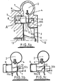
Figures 1a, 1 and 1c are schematic cross-sectional illustrations of part of a known variable geometry turbocharger turbine. -
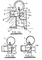
Figures 2a, 2b and 2c illustrate modification of the turbine ofFigures 1a to 1c in accordance with one embodiment of the present invention. -
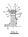
Figure 3 is a schematic cross-section through part of a second known variable geometry turbocharger turbine construction but modified in accordance with an embodiment of the present invention. -
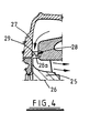
Figure 4 is a schematic cross-section through part of a fixed geometry turbocharger turbine modified in accordance with an embodiment of the present invention. - Referring to
Figure 1 , this is a schematic section through part of a known variable geometry turbocharger turbine which comprises aturbine housing 1 defining a volute orinlet chamber 2 to which gas from an internal combustion engine (not shown) is delivered. The gas flows from theinlet chamber 2 to anaxial outlet passageway 3 via an annular inlet passageway 4 defined on one side by the radial face of anozzle ring 5 and on the other side by anannular shroud plate 6 which covers the opening of anannular recess 7 defined in the opposing wall of thehousing 1. Thenozzle ring 5 is slidably mounted within anannular cavity 8 provided in theturbine housing 1, and is sealed with respect thereto by sealingrings 9. Thenozzle ring 5 supports a circumferential array ofnozzle vanes 10 which extend from the face of thenozzle ring 5 across the inlet passageway 4. Eachvane 10 is cut away at its end remote from thenozzle ring 5 defining atrailing edge 10a and a reducedwidth portion 10b. Although not visible in the figures, in section the vane will typically have an airfoil profile tapering towards thetrailing edge 10a. - In use, gas flowing from the
inlet chamber 2 to theoutlet passageway 3 passes over aturbine wheel 11 which rotates about anaxis 12 and thereby applies torque to aturbocharger shaft 13 which drives a compressor wheel (not shown). The speed of theturbine wheel 11 is dependant upon the velocity of the gas passing through the annular inlet passageway 4. Thevanes 10 are angled to begin turning the gas in the direction of rotation of the turbine wheel. For a fixed rate of flow of gas, the gas velocity is a function of the width of the inlet passageway 4, which can be adjusted by controlling the axial position of the nozzle ring 5 (i.e. by moving it back and forth as indicated by the arrow 14). Movement of thenozzle ring 5 may be controlled by any suitable actuation means. For instance, thenozzle ring 5 may be mounted on axially extending pins (not shown) the position of which is controlled by a stirrup member (not shown) linked to a pneumatically operated actuator (not shown). Since the actuator system may take a variety of conventional forms no particular actuator mechanism is illustrated or described in detail. - In
Figure 1a the nozzle ring is shown in a closed position at which the width of the inlet passageway 4 is reduced to a minimum. In this position it will be seen that the ends of the nozzle vanes 10 abut thehousing 1 within therecess 7, to reducewidth portion 10b of each vane being entirely received within therecess 7. -
Figures 1b and 1c show the nozzle ring in fully open and "over open" positions respectively. In the position illustrated inFigure 1b it will be seen that thenozzle ring 5 is withdrawn part way into thecavity 8 so that the face of thenozzle ring 5 is flush with the wall of the housing and the inlet passageway 4 is at its maximum width. To maximise efficiency the length of thetrailing edge 10a of each vane is sufficient to extend across the inlet passageway 4 when the inlet passageway is fully open as illustrated inFigure 2a . Hence, in this position only the reducedwidth portion 10b of each vane is received within therecess 7. - The swallowing capacity of this particular design of variable geometry turbine can however be increased by further withdrawing the
nozzle ring 5 into thecavity 8 so that the reducedwidth portion 10b of each vane is at least partially retracted from therecess 7 to lie within the inlet passageway 4. This reduces the total vane area obstructing gas flow through the inlet passageway 4 allowing increased gas flow. The maximum flow position is that illustrated inFigure 1c . - As mentioned in the introduction to this specification, a known problem encountered in vaned turbocharger designs is that pressure waves generated as tips of the
turbine wheel blades 11 sweep past the trailing edge of thevanes 10 they interact with a stationary pressure field generated by thevanes 10 which can induce resonant vibrations in theblades 11 leading to stress damage and blade failure. -
Figures 2a to 2c correspond toFigures 1a to 1c but illustrate a modification of the blade profile in accordance with the present invention. Specifically, a discontinuity is provided in the otherwise straight profile of thetrailing edge 10a of each vane in the form of anotch 14 located intermediate the ends of thetrailing edge 10a. Thenotch 14 disturbs and broadens out the pressure field so that the turbine blades experience a less sharp pressure fluctuation as they pass through the wake and thus the excitation of the blades is reduced. This effectively reduces the strain damage to the turbine blades. Since any given mode of vibration can be encountered over a range of inlet passageway widths (since the excitation is dependent on several parameters such as mass flow rate, temperature and pressure of the gas in addition to the passage width) thenotch 14 is positioned to provide influence over as greater range of running conditions as possible. Hence, it can be seen from seen fromFigures 2a and 2b that the notch is positioned so as to be located in the inlet passageway 4 between the minimum and maximum inlet passageway widths. In the over open position illustrated inFigure 2c the notch is withdrawn into thecavity 8 within thehousing 1 but at this stage thecutaway portion 10b of the each vane is exposed in the inlet passageway 4 which also has some effect on disturbing the pressure field and reducing strain on theturbine wheel blades 11. - Referring now to
Figure 3 , this shows a similar modification made to an otherwise conventional swing vane turbine comprising aturbine wheel 15 rotatable about anaxis 16 within a housing defining anannular inlet passageway 17 betweenhousing walls 18 and 19. As with the embodiment described above, exhaust gases flow into theinlet passageway 17 in a radially inwards direction to drive the turbine wheel. Mounted within theinlet passageway 17 is an annular array ofvanes 20 each of which has a respectiveintegral axle 21 that projects through theinlet walls 18 and 19. Acrank 22 is provided at one end of theaxle 20 which in use is coupled to an actuator (not shown) via apin 23 to provide controlled rotation of thevanes 20 about therespective axles 21. With this type of variable geometry turbine the area of theinlet passageway 17 is varied by pivoting eachvane 21 about itsown axle 20 to bring thetrailing edge 21 a of each vane closer to its neighbour thus narrowing theflow passage 17. In accordance with the present invention a discontinuity is provided in the trailingedge 21 a of each vane intermediate its ends to disturb the pressure field generated as theturbine wheel 15 rotates and thereby reduce vibration and damage to the turbine blades. As with the embodiment of the invention described above, the discontinuity in this embodiment is provided by way of anotch 24 formed in the trailingedge 21a. -
Figure 4 illustrates application of the invention to a typical fixed geometry turbocharger provided with inlet vanes. Once again, the turbine comprises aturbine wheel 25 rotatable about anaxis 26 within a housing defining aninlet passageway 27.Fixed vanes 28 extend across theinlet passageway 27 which in accordance with the present invention are provided with anotch 29 in theirtrailing edges 28a. - In each of the above embodiments of the invention the discontinuity provided to disturb the pressure fields takes the form of a notch provided in an otherwise continuous trailing edge. It is anticipated that the precise positioning, profile and size of the notch (i.e. its width and depth) can have a significant effect on the disruption of the wake and that the skilled person will be able to optimise these features of the notch to suit any particular application. Thus, the notch position, shape and size may vary significantly from that illustrated. Similarly, it may be advantageous to provide more than one discontinuity (e.g. more than one notch - possibly of different sizes/shapes in the trailing edge) in certain applications.
- The same effect may also be achieved by profiling the trailing edge of each vane so as to deviate from a straight line for at least part of its length in ways other than by forming a notch in the edge. For instance, the trailing edge could be curved either in a circumferential direction relative to rotation of the turbine wheel (effectively by varying the camber of each vane along its length), or in a radial direction, or a combination of both. Such curvature could be provided along the whole length of the trailing edge of each vane or along only a portion or portions of its length. Moreover, such curved edges could be combined with other discontinuities, such as notches as described above.
- It will be appreciated that the invention can be applied to any turbocharger turbine incorporating an array of vanes adjacent the area swept out by the turbine wheel blades and is not limited to the particular constructions and geometries described above. Other possible modifications of the invention will be readily apparent to the appropriately skilled person.
Claims (10)
- A turbocharger including a turbine comprising a turbine wheel (11; 15) having radial blades and supported in a housing (1) for rotation about an axis, an annular inlet passageway (4;17) extending radially inwards towards the turbine wheel (11;15), the inlet passageway (4; 17) being defined between first and second facing annular walls (5,6;18,19), an annular array of vanes (10;20) extending across the inlet passageway (4;17), each vane having a trailing edge (10a;21a) extending adjacent the turbine wheel blades, wherein the trailing edge (10a;21a) of each vane deviates from a straight line over at least a portion of its length defined between its ends, characterized in that said deviation is provided by a notch (14;24) defined in the trailing edge.
- A turbine according to claim 1, wherein portions of the trailing edge (10a;21a) of each vane on either side of said notch (14;24) at least substantially lie on the same straight line.
- A turbine according to claim 2, wherein said line is substantially parallel to lines defined by tips of the turbine wheel blades.
- The turbine according to any preceding claim, wherein the trailing edge of each vane is curved along at least a portion of its length in a circumferential and/or radial direction relative to the axis of rotation of the turbine wheel.
- A turbine according to any preceding claim, comprising a plurality of notches (14;24) in the trailing edge of each vane.
- A turbine according to any preceeding claim, wherein the geometry of the inlet passageway (4; 17) is variable.
- A turbine according to claim 6, wherein the first wall is defined by a moveable wall member (5) which is moveable relative to the facing wall (6) to vary the width of the inlet passageway (4).
- A turbine according to claim 7, wherein the vanes (10) are supported by the moveable wall member (5) and said facing wall (6) is provided with a recess or recesses to receive ends of the vanes.
- A turbine according to claim 7, wherein the moveable wall member is slotted to receive said vanes which extend from the facing wall.
- A turbine according to claim 6, where each vane (20) is rotatably mounted about a respective axis (21) extending across the inlet passageway (17), the vanes being coupled to an actuator which is displaceable to cause the vanes the pivot about said axes within the inlet passageway (17).
Applications Claiming Priority (2)
| Application Number | Priority Date | Filing Date | Title |
|---|---|---|---|
| GBGB0213910.3A GB0213910D0 (en) | 2002-06-17 | 2002-06-17 | Turbine |
| GB0213910 | 2002-06-17 |
Publications (2)
| Publication Number | Publication Date |
|---|---|
| EP1375826A1 EP1375826A1 (en) | 2004-01-02 |
| EP1375826B1 true EP1375826B1 (en) | 2011-07-20 |
Family
ID=9938744
Family Applications (1)
| Application Number | Title | Priority Date | Filing Date |
|---|---|---|---|
| EP03253014A Expired - Lifetime EP1375826B1 (en) | 2002-06-17 | 2003-05-15 | Radial turbine with guide vanes for reducing vibrations |
Country Status (6)
| Country | Link |
|---|---|
| US (1) | US6932565B2 (en) |
| EP (1) | EP1375826B1 (en) |
| JP (1) | JP2004019663A (en) |
| KR (1) | KR20040002526A (en) |
| CN (1) | CN1288333C (en) |
| GB (1) | GB0213910D0 (en) |
Families Citing this family (24)
| Publication number | Priority date | Publication date | Assignee | Title |
|---|---|---|---|---|
| US7207176B2 (en) | 2002-11-19 | 2007-04-24 | Cummins Inc. | Method of controlling the exhaust gas temperature for after-treatment systems on a diesel engine using a variable geometry turbine |
| US7150151B2 (en) * | 2002-11-19 | 2006-12-19 | Cummins Inc. | Method of controlling the exhaust gas temperature for after-treatment systems on a diesel engine using a variable geometry turbine |
| US7280950B2 (en) * | 2004-01-22 | 2007-10-09 | Electro-Motive Diesel, Inc. | Locomotive diesel engine turbocharger and turbine stage constructed with turbine blade vibration suppression methodology |
| JP2011021612A (en) * | 2004-05-06 | 2011-02-03 | Cummins Inc | Method of determining exhaust gas temperature for after-treatment system on internal combustion engine using variable geometry turbine |
| DE102005027080A1 (en) * | 2005-06-11 | 2006-12-14 | Daimlerchrysler Ag | Exhaust gas turbine in an exhaust gas turbocharger |
| GB0521354D0 (en) | 2005-10-20 | 2005-11-30 | Holset Engineering Co | Variable geometry turbine |
| US20070175214A1 (en) * | 2006-01-30 | 2007-08-02 | Reisdorf Paul W | Turbocharger having divided housing with nozzle vanes |
| GB0615495D0 (en) * | 2006-08-04 | 2006-09-13 | Cummins Turbo Tech Ltd | Variable geometry turbine |
| ITMI20061738A1 (en) * | 2006-09-12 | 2008-03-13 | Iveco Motorenforschung Ag | VARIABLE GEOMETRY TURBINE |
| US20100150701A1 (en) * | 2007-06-26 | 2010-06-17 | Borgwarner Inc. | Variable geometry turbocharger |
| EP2077312A1 (en) | 2007-12-17 | 2009-07-08 | Nippon Oil Corporation | Fuels for homogeneous charge compression ignition combustion engine |
| GB0805519D0 (en) * | 2008-03-27 | 2008-04-30 | Cummins Turbo Tech Ltd | Variable geometry turbine |
| GB2462115A (en) * | 2008-07-25 | 2010-01-27 | Cummins Turbo Tech Ltd | Variable geometry turbine |
| KR101036591B1 (en) * | 2009-04-03 | 2011-05-24 | 김병섭 | Rebar coupler |
| DE102010051359A1 (en) * | 2010-11-13 | 2012-05-16 | Daimler Ag | Insert element for a turbine of an exhaust gas turbocharger, exhaust gas turbocharger and turbine for an exhaust gas turbocharger |
| US8627660B2 (en) * | 2010-12-02 | 2014-01-14 | Toyota Jidosha Kabushiki Kaisha | Control device for internal combustion engine with supercharger |
| US10072513B2 (en) | 2011-11-30 | 2018-09-11 | Mitsubishi Heavy Industries, Ltd. | Radial turbine |
| DE112013003162T5 (en) * | 2012-07-27 | 2015-03-12 | Borgwarner Inc. | Retractable bladed diffuser for compressors |
| DE102012108975A1 (en) * | 2012-09-24 | 2014-03-27 | Firma IHI Charging Systems International GmbH | Adjustable distributor for an exhaust gas turbocharger and turbocharger |
| US9963974B2 (en) | 2012-10-23 | 2018-05-08 | United Technologies Corporation | Reduction of equally spaced turbine nozzle vane excitation |
| GB2571356A (en) * | 2018-02-27 | 2019-08-28 | Cummins Ltd | Variable geometry turbine |
| CN109779741B (en) * | 2019-01-23 | 2020-05-19 | 宁波天阁汽车零部件有限公司 | Automobile-used turbo charger |
| JP7423557B2 (en) * | 2021-01-21 | 2024-01-29 | 三菱重工エンジン&ターボチャージャ株式会社 | Variable displacement turbine and supercharger |
| US11732601B2 (en) | 2021-12-06 | 2023-08-22 | Borgwarner Inc. | Variable turbine geometry assembly |
Citations (1)
| Publication number | Priority date | Publication date | Assignee | Title |
|---|---|---|---|---|
| US4318669A (en) * | 1980-01-07 | 1982-03-09 | The United States Of America As Represented By The Secretary Of The Air Force | Vane configuration for fluid wake re-energization |
Family Cites Families (8)
| Publication number | Priority date | Publication date | Assignee | Title |
|---|---|---|---|---|
| US4292807A (en) * | 1979-05-02 | 1981-10-06 | United Technologies Corporation | Variable geometry turbosupercharger system for internal combustion engine |
| DE3541508C1 (en) * | 1985-11-23 | 1987-02-05 | Kuehnle Kopp Kausch Ag | Exhaust gas turbocharger |
| US4741666A (en) * | 1985-12-23 | 1988-05-03 | Ishikawajima-Harima Jukogyo Kabushiki Kaisha | Variable displacement turbocharger |
| GB8829792D0 (en) * | 1988-12-21 | 1989-07-05 | Marconi Co Ltd | Noise reduction method |
| JP3153409B2 (en) * | 1994-03-18 | 2001-04-09 | 株式会社日立製作所 | Manufacturing method of centrifugal compressor |
| AT405756B (en) * | 1996-05-30 | 1999-11-25 | Efg Turbinen Und Kraftwerksanl | Guide vane for tubular turbines |
| GB2326198A (en) | 1997-06-10 | 1998-12-16 | Holset Engineering Co | Variable geometry turbine |
| EP1301689B1 (en) * | 2000-07-19 | 2006-09-20 | Honeywell Garrett SA | Sliding vane turbocharger with graduated vanes |
-
2002
- 2002-06-17 GB GBGB0213910.3A patent/GB0213910D0/en not_active Ceased
-
2003
- 2003-05-15 EP EP03253014A patent/EP1375826B1/en not_active Expired - Lifetime
- 2003-06-04 KR KR1020030036019A patent/KR20040002526A/en not_active Ceased
- 2003-06-13 US US10/461,845 patent/US6932565B2/en not_active Expired - Lifetime
- 2003-06-16 JP JP2003170567A patent/JP2004019663A/en active Pending
- 2003-06-17 CN CNB03141088XA patent/CN1288333C/en not_active Expired - Fee Related
Patent Citations (1)
| Publication number | Priority date | Publication date | Assignee | Title |
|---|---|---|---|---|
| US4318669A (en) * | 1980-01-07 | 1982-03-09 | The United States Of America As Represented By The Secretary Of The Air Force | Vane configuration for fluid wake re-energization |
Also Published As
| Publication number | Publication date |
|---|---|
| CN1469035A (en) | 2004-01-21 |
| US6932565B2 (en) | 2005-08-23 |
| JP2004019663A (en) | 2004-01-22 |
| CN1288333C (en) | 2006-12-06 |
| KR20040002526A (en) | 2004-01-07 |
| GB0213910D0 (en) | 2002-07-31 |
| US20040101402A1 (en) | 2004-05-27 |
| EP1375826A1 (en) | 2004-01-02 |
Similar Documents
| Publication | Publication Date | Title |
|---|---|---|
| US6932565B2 (en) | Turbine | |
| EP1099838B1 (en) | Variable displacement turbo supercharger | |
| CN1680683B (en) | variable geometry turbine | |
| EP1903187B1 (en) | Leaned high pressure compressor inlet guide vane | |
| EP2123861B1 (en) | Mixed flow turbine for a turbocharger | |
| EP1353040B1 (en) | Variable geometry turbine | |
| US6402465B1 (en) | Ring valve for turbine flow control | |
| US8672619B2 (en) | Turbocharger vane | |
| JPH0874502A (en) | Turbine blade | |
| JP2005299660A5 (en) | ||
| CA2694659A1 (en) | Variable stator vane contoured button | |
| EP2623728B1 (en) | Variable geometry turbine | |
| WO2009118528A1 (en) | Variable geometry turbine | |
| EP3004588B1 (en) | Turbocharger with progressively variable a/r ratio | |
| EP1481151B1 (en) | Improved vane design for use in variable geometry-turbocharger | |
| JP5427900B2 (en) | Mixed flow turbine | |
| JPS63147903A (en) | Turbine casing structure | |
| JP2000204907A (en) | Variable displacement turbine | |
| EP3569827B1 (en) | Variable diffuser having a respective penny for each vane | |
| EP3567222B1 (en) | Variable diffuser having a respective penny for each vane | |
| JPH09264106A (en) | Exhaust diffuser for turbine | |
| JPH11141343A (en) | Variable capacity turbine | |
| JPH10205340A (en) | Variable displacement turbine | |
| WO2024201987A1 (en) | Variable nozzle device and variable capacity-type exhaust turbocharger | |
| CN116498395A (en) | Non-uniform turbine blade tips for frequency tuning |
Legal Events
| Date | Code | Title | Description |
|---|---|---|---|
| PUAI | Public reference made under article 153(3) epc to a published international application that has entered the european phase |
Free format text: ORIGINAL CODE: 0009012 |
|
| AK | Designated contracting states |
Kind code of ref document: A1 Designated state(s): AT BE BG CH CY CZ DE DK EE ES FI FR GB GR HU IE IT LI LU MC NL PT RO SE SI SK TR |
|
| AX | Request for extension of the european patent |
Extension state: AL LT LV MK |
|
| AKX | Designation fees paid | ||
| REG | Reference to a national code |
Ref country code: DE Ref legal event code: 8566 |
|
| 17P | Request for examination filed |
Effective date: 20040914 |
|
| RBV | Designated contracting states (corrected) |
Designated state(s): DE FR GB |
|
| 17Q | First examination report despatched |
Effective date: 20041103 |
|
| 17Q | First examination report despatched |
Effective date: 20041103 |
|
| GRAJ | Information related to disapproval of communication of intention to grant by the applicant or resumption of examination proceedings by the epo deleted |
Free format text: ORIGINAL CODE: EPIDOSDIGR1 |
|
| GRAP | Despatch of communication of intention to grant a patent |
Free format text: ORIGINAL CODE: EPIDOSNIGR1 |
|
| GRAP | Despatch of communication of intention to grant a patent |
Free format text: ORIGINAL CODE: EPIDOSNIGR1 |
|
| GRAS | Grant fee paid |
Free format text: ORIGINAL CODE: EPIDOSNIGR3 |
|
| RAP1 | Party data changed (applicant data changed or rights of an application transferred) |
Owner name: CUMMINS TURBO TECHNOLOGIES LIMITED |
|
| GRAA | (expected) grant |
Free format text: ORIGINAL CODE: 0009210 |
|
| AK | Designated contracting states |
Kind code of ref document: B1 Designated state(s): DE FR GB |
|
| REG | Reference to a national code |
Ref country code: GB Ref legal event code: FG4D |
|
| REG | Reference to a national code |
Ref country code: DE Ref legal event code: R096 Ref document number: 60337727 Country of ref document: DE Effective date: 20110908 |
|
| PLBE | No opposition filed within time limit |
Free format text: ORIGINAL CODE: 0009261 |
|
| STAA | Information on the status of an ep patent application or granted ep patent |
Free format text: STATUS: NO OPPOSITION FILED WITHIN TIME LIMIT |
|
| 26N | No opposition filed |
Effective date: 20120423 |
|
| REG | Reference to a national code |
Ref country code: DE Ref legal event code: R097 Ref document number: 60337727 Country of ref document: DE Effective date: 20120423 |
|
| REG | Reference to a national code |
Ref country code: FR Ref legal event code: PLFP Year of fee payment: 14 |
|
| REG | Reference to a national code |
Ref country code: FR Ref legal event code: PLFP Year of fee payment: 15 |
|
| REG | Reference to a national code |
Ref country code: FR Ref legal event code: PLFP Year of fee payment: 16 |
|
| PGFP | Annual fee paid to national office [announced via postgrant information from national office to epo] |
Ref country code: FR Payment date: 20210525 Year of fee payment: 19 Ref country code: DE Payment date: 20210527 Year of fee payment: 19 |
|
| PGFP | Annual fee paid to national office [announced via postgrant information from national office to epo] |
Ref country code: GB Payment date: 20210527 Year of fee payment: 19 |
|
| REG | Reference to a national code |
Ref country code: DE Ref legal event code: R119 Ref document number: 60337727 Country of ref document: DE |
|
| GBPC | Gb: european patent ceased through non-payment of renewal fee |
Effective date: 20220515 |
|
| PG25 | Lapsed in a contracting state [announced via postgrant information from national office to epo] |
Ref country code: FR Free format text: LAPSE BECAUSE OF NON-PAYMENT OF DUE FEES Effective date: 20220531 |
|
| PG25 | Lapsed in a contracting state [announced via postgrant information from national office to epo] |
Ref country code: GB Free format text: LAPSE BECAUSE OF NON-PAYMENT OF DUE FEES Effective date: 20220515 Ref country code: DE Free format text: LAPSE BECAUSE OF NON-PAYMENT OF DUE FEES Effective date: 20221201 |
|
| P01 | Opt-out of the competence of the unified patent court (upc) registered |
Effective date: 20230510 |