CN1288333C - Turbine - Google Patents
Turbine Download PDFInfo
- Publication number
- CN1288333C CN1288333C CNB03141088XA CN03141088A CN1288333C CN 1288333 C CN1288333 C CN 1288333C CN B03141088X A CNB03141088X A CN B03141088XA CN 03141088 A CN03141088 A CN 03141088A CN 1288333 C CN1288333 C CN 1288333C
- Authority
- CN
- China
- Prior art keywords
- turbine
- gas
- nozzle vane
- trailing edge
- entered passageway
- Prior art date
- Legal status (The legal status is an assumption and is not a legal conclusion. Google has not performed a legal analysis and makes no representation as to the accuracy of the status listed.)
- Expired - Fee Related
Links
Images


Classifications
-
- F—MECHANICAL ENGINEERING; LIGHTING; HEATING; WEAPONS; BLASTING
- F02—COMBUSTION ENGINES; HOT-GAS OR COMBUSTION-PRODUCT ENGINE PLANTS
- F02B—INTERNAL-COMBUSTION PISTON ENGINES; COMBUSTION ENGINES IN GENERAL
- F02B37/00—Engines characterised by provision of pumps driven at least for part of the time by exhaust
- F02B37/12—Control of the pumps
- F02B37/22—Control of the pumps by varying cross-section of exhaust passages or air passages, e.g. by throttling turbine inlets or outlets or by varying effective number of guide conduits
-
- F—MECHANICAL ENGINEERING; LIGHTING; HEATING; WEAPONS; BLASTING
- F01—MACHINES OR ENGINES IN GENERAL; ENGINE PLANTS IN GENERAL; STEAM ENGINES
- F01D—NON-POSITIVE DISPLACEMENT MACHINES OR ENGINES, e.g. STEAM TURBINES
- F01D17/00—Regulating or controlling by varying flow
- F01D17/10—Final actuators
- F01D17/12—Final actuators arranged in stator parts
- F01D17/14—Final actuators arranged in stator parts varying effective cross-sectional area of nozzles or guide conduits
- F01D17/16—Final actuators arranged in stator parts varying effective cross-sectional area of nozzles or guide conduits by means of nozzle vanes
- F01D17/167—Final actuators arranged in stator parts varying effective cross-sectional area of nozzles or guide conduits by means of nozzle vanes of vanes moving in translation
-
- F—MECHANICAL ENGINEERING; LIGHTING; HEATING; WEAPONS; BLASTING
- F01—MACHINES OR ENGINES IN GENERAL; ENGINE PLANTS IN GENERAL; STEAM ENGINES
- F01D—NON-POSITIVE DISPLACEMENT MACHINES OR ENGINES, e.g. STEAM TURBINES
- F01D17/00—Regulating or controlling by varying flow
- F01D17/10—Final actuators
- F01D17/12—Final actuators arranged in stator parts
- F01D17/14—Final actuators arranged in stator parts varying effective cross-sectional area of nozzles or guide conduits
- F01D17/16—Final actuators arranged in stator parts varying effective cross-sectional area of nozzles or guide conduits by means of nozzle vanes
- F01D17/165—Final actuators arranged in stator parts varying effective cross-sectional area of nozzles or guide conduits by means of nozzle vanes for radial flow, i.e. the vanes turning around axes which are essentially parallel to the rotor centre line
-
- F—MECHANICAL ENGINEERING; LIGHTING; HEATING; WEAPONS; BLASTING
- F01—MACHINES OR ENGINES IN GENERAL; ENGINE PLANTS IN GENERAL; STEAM ENGINES
- F01D—NON-POSITIVE DISPLACEMENT MACHINES OR ENGINES, e.g. STEAM TURBINES
- F01D5/00—Blades; Blade-carrying members; Heating, heat-insulating, cooling or antivibration means on the blades or the members
- F01D5/12—Blades
- F01D5/14—Form or construction
- F01D5/141—Shape, i.e. outer, aerodynamic form
Abstract
A turbine comprises a turbine wheel (11) having radial blades and supported in a housing (1) for rotation about an axis (12). An annular inlet passageway (4) extends radially inwards towards the turbine wheel, the inlet passageway (4) being defined between first and second facing annular walls (5,6). An annular array of vanes (10) extend across the inlet passageway (4). Each vane (10) has a trailing edge (10a) extending adjacent the turbine wheel blades, wherein the trailing edge (10a) of each vane (10) deviates from a straight line over at least a portion of its length defined between its ends.
Description
Technical field
The present invention relates to a kind of turbine, the turbine in particularly a kind of turbosupercharger that is applicable to internal-combustion engine.
Background technique
Turbosupercharger of the prior art, its turbine stage comprises a turbine chamber, and a turbine that is installed in this turbine chamber, one be positioned at around the turbine chamber annular inlet passageway, one is positioned at a suction port and the exhaust passage from the turbine chamber extension around this annular inlet passageway.Gas exchange between passage and chamber is that the waste gas with certain pressure that enters into air-inlet cavity flows to the exhaust passage by gas-entered passageway through turbine chamber.One has radially, and the turbine wheel of extended blade is installed in the turbine chamber, is promoted to be rotated by gas.
As everyone knows, blade that can be by being positioned at gas-entered passageway for example nozzle vane is regulated turbine performance, and the air-flow that makes the gas-entered passageway of flowing through like this deflects along the direction of turbine wheel rotation.
Turbine can be in a fixed geometry turbine or the variable geometry turbine a kind of.The difference of variable geometry turbine and fixed geometry turbine just is, the dimensional changes of its gas-entered passageway makes under the flow situation of certain limit, can the speed of gas in the passage be optimized, thereby the output power that can change turbine is to adapt to the engine demand of variation.The modal structure of this variable geometry turbine is, its each blade with self axis that extends through gas-entered passageway be rotating shaft (be generally along length of blade half certain a bit on), the driving mechanism of blade can be connected on each blade, and be movably, this mode makes that each blade can both be in phase around self axis rotation, make each vane trailing edge (just near the edge of turbine wheel) forward or away from contiguous blade, thereby change the area that is used for the section that gas enters and the flow angle of turbine wheel.The so-called oscillating vane variable geometry turbine of this structure.
The another kind of common structure of variable geometry turbine is, one of them wall of gas-entered passageway is a wall elements movably, is generally a nozzle ring, and it is adjustable with respect to a relative wall's of gas-entered passageway position, thus the width of control gas-entered passageway.For example, when the throughput of the turbine of flowing through reduced, the width of gas-entered passageway also can reduce, thereby kept the speed of air-flow and the output power of optimization turbine.In some cases, nozzle vane is fixed in position, but extends through the slit that is positioned at a removable nozzle ring, and other blade extends to slit on the relative wall who is positioned at gas-entered passageway from a removable nozzle ring.
Have in the variable geometry turbine of removable nozzle ring, prior art is the nozzle ring that " excessively opening " arranged, by its withdrawal is surpassed the nominal whole width of gas-entered passageway, blade is withdrawn from gas-entered passageway at least in part, thereby improve the maximum area of passage and the throughput of gas-entered passageway.In the improvement to this system, prior art is away from nozzle ring, and a part of blade is excised in the tail end of nozzle vane.So just, the length and the height (blades height be meant distance that it from nozzle ring extend) of nozzle vane on width segments of nozzle ring trailing edge have been shortened.Like this, the zone that the afterbody of each blade has a width to reduce, when nozzle ring was in excessive open mode, this zone was positioned at gas-entered passageway, thereby had increased the area of passage of gas-entered passageway.
The turbine of which kind of form no matter, its nozzle vane generally all is static, promptly they can not rotate together with turbine wheel.Because the impeller blade of rotation and brings a known problem by the interaction between the static pressure district of nozzle ring generation.Promptly under some rotating speed, this interactional periodicity is consistent with the vibration frequency of blade under one or more vibrational modes, produces vibration in blade.Vibration strain on this turbine blade makes blade be subjected to very big damage.
Summary of the invention
Goal of the invention of the present invention just is to eliminate or alleviate above problem.
The present invention just is to provide a kind of turbine that comprises a turbine wheel, this turbine wheel with radial blade is around a rotation, be supported in the housing, the gas-entered passageway of one annular is towards the radially direction extension of Xiangli of turbine wheel, this gas-entered passageway is between the first and second relative ring wall surfaces, one rows of blades of arranging in the form of a ring extends through gas-entered passageway, each vane trailing edge is all adjacent with turbine blade, and described each vane trailing edge departs from a straight line at it on the direction of partial-length at least between its end.
This departs from can be one to be positioned at the form of discontinuous portion of trailing edge or one section curve on trailing edge, and its disturbs the pressure area that is produced by blade, particularly reduces because the damage that vibration brings to turbine blade.
Optiaml characteristics of the present invention as can be seen from the following description.
Description of drawings
Below in conjunction with accompanying drawing, will be described in detail preferred embodiment of the present invention.
Fig. 1 a, 1b, 1c are a kind of schematic sectional drawing of known variable geometry turbine.
Fig. 2 a, 2b, 2c are the embodiment after the present invention improves the turbine as Fig. 1 a-1c.
Fig. 3 is the embodiment of the present invention after the part-structure of another known variable geometry turbine is improved sectional drawing.
Fig. 4 is the sectional drawing of the embodiment after the present invention improves the fixed geometry turbine part.
Embodiment
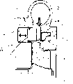
As shown in Figure 1, a kind of schematic part sectioned view of known variable geometry turbine comprises a turbine shroud 1 that is formed by a spiral case or air-inlet cavity 2, is transported in volute or the air-inlet cavity 2 from the gas of internal-combustion engine (not shown).Gas flows to an axial exhaust ducts 3 through an annular inlet passageway 4 from air-inlet cavity 2, a wherein wall of described annular inlet passageway 4 is formed by the radial surface of nozzle ring 5, another wall is formed by a ring-shaped baffle 6, and this ring-shaped baffle 6 covers the opening of the annular recess 7 on the reverse wall that is positioned at housing 1.Nozzle ring 5 is slidably mounted in the toroidal cavity 8 that is arranged in turbine shroud 1, by seal ring 9 realization relative sealings therebetween.The circumferential row of nozzle ring 5 supportings one nozzle vane 10, this nozzle vane 10 extends from the surface of nozzle ring 5, passes gas-entered passageway 4.Each nozzle vane 10 is cut in its end portion away from nozzle ring 5, limits the trailing edge 10a of a nozzle vane and the part 10b that a width reduces.Though also not shown among the figure, in the sectional drawing of nozzle vane, have the tapered airfoil profile of hinder marginal part 10a on one day usually.
In the course of the work, the gas that flows to exhaust passage 3 from air-inlet cavity 2 is through one when the turbine wheel 11 of axis 12 rotations, with a torque on the turbo-charger shaft 13 that drives a compressor impeller (not shown).The rotating speed of turbine wheel 11 is along with the gas velocity by annular inlet passageway 4 changes.Nozzle vane 10 with several angle makes airflow direction change to sense of rotation along turbine wheel.In throughput is under the situation of certain value, and gas flow rate is the function of gas-entered passageway 4 width, and this width can be adjusted (this nozzle ring just moves around) by the axial position of control nozzle ring 5 on the direction of arrow as shown in the figure.Moving of this nozzle ring 5 can be by any suitable driving mode control.For example, this nozzle ring 5 can be installed on the axially extended pin (not shown), and the position of this pin is by a stirrup (not shown) control that is connected to by (not shown) on the air-controlled driving mechanism.Because this drive system can adopt a lot of existing structures, so no longer this driving mechanism is described in detail here.
As Fig. 1 a, nozzle ring 5 is in the closed position, and this moment, the width of gas-entered passageway 4 was a minimum value.When nozzle ring 5 during in this position, the end of nozzle vane 10 is mutually close with the housing 1 that is positioned at groove 7, fully takes in the groove 7 thereby the width on each nozzle vane reduces part 10b.
Fig. 1 b and 1c show nozzle ring 5 and are in the state of opening fully and excessively opening respectively.Shown in Fig. 1 b, nozzle ring 5 is partially retracted in cavity 8, and at this moment the surface of nozzle ring 5 flushes with the wall of housing, and gas-entered passageway 4 is in Extreme breadth.In order to reach peak efficiency, when gas-entered passageway 4 was opened fully, shown in Fig. 1 c, the whole length of the trailing edge 10a of each nozzle vane all extended through gas-entered passageway 4.Like this, when nozzle ring 5 was in this position, each nozzle vane only had only the part 10b that wherein reduces width to be positioned at groove 7.
Yet, the throughput of the variable geometry turbine of this particular design can be improved because of nozzle ring 5 further is withdrawn in the cavity 8, at this moment the width of each nozzle vane reduces part 10b at least in part from groove 7 withdrawals, is horizontally placed in the gas-entered passageway 4.This has reduced to hinder the whole nozzle vane zone that air communication is crossed gas-entered passageway 4, and throughput is increased.The position of maximum airflow is shown in Fig. 1 c.
As what in the introduction of specification of the present invention, mention, occurring an existing problem in the design of blade type turbosupercharger is, when the trailing edge of the inswept nozzle vane 10 in the top of turbine blade 11, produce a pressure wave, this pressure wave and a static pressure district that is produced by nozzle vane 10 interact, cause resonance 11 of turbine blades, cause stress damage and turbine blade to damage.
To Fig. 1 c, Fig. 2 a is the improvement of the present invention to the turbine blade profile to Fig. 2 c corresponding to Fig. 1 a.Be specially, a discontinuous structure is arranged in the outline of straight line of each nozzle vane trailing edge 10a, this structure is positioned at the centre of trailing edge 10a end with the form of a groove 14.This groove 14 disturbs and has enlarged described pressure span, like this, when this whirlpool district (wake) of turbine blade process, bears the pressure surge that relaxes, thereby has reduced the disturbance to turbine blade.This mode has reduced the stress infringement to turbine blade effectively.Because any type of vibration all may exist (because disturbance depends on several parameters in the gas-entered passageway width range, for example except width of flow path, also have gas flow rate, temperature and gas pressure), the location of groove 14 should be able to influence bigger as far as possible operating conditions scope.Like this, as Fig. 2 a, shown in the 2b, groove 14 is located between the minimum and maximum width of gas-entered passageway 4.Shown in Fig. 2 c, when nozzle ring is in the state of excessively opening, groove 4 is withdrawn into the cavity 8 that is arranged in housing 1, but in this state, the cutting part 10b of each nozzle vane is exposed in the gas-entered passageway 4, so also can exert an influence, alleviate damage turbine blade 11 to disturbing described pressure area.Described or each groove is arranged in the trailing edge with outline of straight line of nozzle vane.Described outline of straight line parallels with the straight line that is limited by the turbine wheel vane tip basically.
Refer now to Fig. 3, the figure shows the improvement to another traditional oscillating-blade turbine, this turbine comprises a turbine wheel 15 around axis 16 rotations, and this impeller is positioned at a housing, and this housing limits a ring-type gas-entered passageway 17 between shell body wall 18,19.Aforesaid embodiment, waste gas flows in the gas-entered passageway 17 along a radially inner direction, drives turbine wheel.Each of rows of blades that is installed in the nozzle vane of arranging in the form of a ring 20 in the gas-entered passageway 17 all each has axon 21 one by one, and this axle 21 passes wall 18 and 19 and stretch out.One bent axle 22 is positioned at an end of axle 21, and it links to each other with a driving mechanism (not shown) by a pin 23, and the control nozzle vane rotates around axle 21 separately.In this variable geometry turbine, by each nozzle vane 20 around its separately axle 21 rotation make the trailing edge 21a of each nozzle vane and its adjacent nozzles vane trailing edge more close, make gas-entered passageway 17 become narrow, thereby the area of gas-entered passageway 17 is changed.According to the present invention, a discontinuous portion is positioned in the middle of the end of each trailing edge 21a, is used to disturb the pressure area by the rotation generation of impeller 15, thus the infringement that alleviates vibration and bring to turbine blade.Identical with aforementioned embodiments of the invention, this discontinuous portion is limited at the groove 24 in the trailing edge 21a in the present embodiment.
Fig. 4 is for to be applied in the present invention in a kind of fixed geometry turbine that has the entry nozzle blade commonly used.As previously mentioned, turbine comprises a turbine wheel 25 that rotates around axis 26, and this impeller is positioned at a housing that has a gas-entered passageway 27.Fixed blade 28 extends through described gas-entered passageway 27, according to the present invention, a groove 29 is arranged in trailing edge 28a.
In each embodiment of the invention described above, describedly be a form of grooves that is positioned at continuous trailing edge in order to the discontinuous portion that disturbs the pressure area.Predictably accurate location, profile and the size of this groove (be width and height) all can to the whirlpool district disintegrate the generation significant effects, and those skilled in the art can be optimized these parameters of groove, make it be applicable to any special occasions.Like this, the position of groove, shape and size may have a great difference with the diagram part.Equally, in some occasion, adopt more than one discontinuous portion also be good (for example, be positioned at the more than groove of hinder marginal part and have different size/shape one by one).
Same effect can obtain, by with each trailing edge profile variations on its partial-length direction, departing from a straight line at least, but not form the mode of a groove.For example, trailing edge can be along one with respect to the circumferencial direction of the rotation of turbine wheel or radially, is arc (by changing each blade along the radian on its length direction) along both compound direction perhaps.This bending can be along on the whole length direction of each trailing edge portion, also can be on the length direction of the part of trailing edge or several parts.In addition, this curved edges can be used in combination with the discontinuous portion of other form, for example, and aforesaid groove.
The present invention can be applied to any turbine, and this turbine has one group of blade, this blade and adjacent by the inswept zone of turbine blade, and be not limited to above-mentioned special construction of mentioning and geometrical shape.Other possible improvement of the present invention is clearly to those skilled in the art.
Claims (11)
1. turbine, comprise that one has the turbine wheel of radial blade, this impeller is supported in the housing, rotate around an axis, the annular inlet passageway that one day, turbine wheel radially extended internally, this passage are limited between first and second ring wall surfaces of facing, the nozzle vane of row's ring-type configuration, extend through this gas-entered passageway, each nozzle vane all has a trailing edge adjacent with the turbine wheel blade;
Trailing edge at each nozzle vane has at least one groove in the middle of its end.
2. turbine as claimed in claim 1 is characterized in that: the groove that comprises the trailing edge of some each nozzle vanes.
3. turbine as claimed in claim 1 or 2 is characterized in that: described or each groove is arranged in the trailing edge with outline of straight line of nozzle vane.
4. turbine as claimed in claim 3 is characterized in that: described outline of straight line parallels with the straight line that is limited by the turbine wheel vane tip basically.
5. turbine as claimed in claim 1 or 2 is characterized in that: the trailing edge of each nozzle vane along with respect to the circumference of turbine wheel spin axis and/or radial direction along its at least partial-length be arc.
6. turbine as claimed in claim 1 or 2 is characterized in that: the geometrical shape of described gas-entered passageway is transformable.
7. turbine as claimed in claim 6 is characterized in that: described first wall by one movably wall spare limit, this movably wall spare be movably with respect to this in the face of wall, thereby change the width of gas-entered passageway.
8. turbine as claimed in claim 7 is characterized in that: described nozzle vane is by movably wall spare supporting, and the described wall of facing is provided with the groove that one or several is used for the fanging noz(zle) blade tip.
9. turbine as claimed in claim 7 is characterized in that: this removable wall spare has groove, is used to receive from the extended described nozzle vane of this wall of facing.
10. turbine as claimed in claim 6, it is characterized in that: this each nozzle vane is installed into can be around the rotational of passing gas-entered passageway separately, these nozzle vanes link to each other with a driver, and this driver is movably, and nozzle vane is swung around described axis in gas-entered passageway.
11. a turbosupercharger comprises turbine as claimed in claim 1 or 2.
Applications Claiming Priority (2)
| Application Number | Priority Date | Filing Date | Title |
|---|---|---|---|
| GB0213910.3 | 2002-06-17 | ||
| GBGB0213910.3A GB0213910D0 (en) | 2002-06-17 | 2002-06-17 | Turbine |
Publications (2)
| Publication Number | Publication Date |
|---|---|
| CN1469035A CN1469035A (en) | 2004-01-21 |
| CN1288333C true CN1288333C (en) | 2006-12-06 |
Family
ID=9938744
Family Applications (1)
| Application Number | Title | Priority Date | Filing Date |
|---|---|---|---|
| CNB03141088XA Expired - Fee Related CN1288333C (en) | 2002-06-17 | 2003-06-17 | Turbine |
Country Status (6)
| Country | Link |
|---|---|
| US (1) | US6932565B2 (en) |
| EP (1) | EP1375826B1 (en) |
| JP (1) | JP2004019663A (en) |
| KR (1) | KR20040002526A (en) |
| CN (1) | CN1288333C (en) |
| GB (1) | GB0213910D0 (en) |
Families Citing this family (24)
| Publication number | Priority date | Publication date | Assignee | Title |
|---|---|---|---|---|
| US7150151B2 (en) * | 2002-11-19 | 2006-12-19 | Cummins Inc. | Method of controlling the exhaust gas temperature for after-treatment systems on a diesel engine using a variable geometry turbine |
| US7207176B2 (en) | 2002-11-19 | 2007-04-24 | Cummins Inc. | Method of controlling the exhaust gas temperature for after-treatment systems on a diesel engine using a variable geometry turbine |
| US7280950B2 (en) * | 2004-01-22 | 2007-10-09 | Electro-Motive Diesel, Inc. | Locomotive diesel engine turbocharger and turbine stage constructed with turbine blade vibration suppression methodology |
| JP5140135B2 (en) * | 2004-05-06 | 2013-02-06 | カミンズ インコーポレーテッド | Variable geometry turbocharger and system for determining exhaust gas temperature for aftertreatment systems in an internal combustion engine using a variable geometry turbine |
| DE102005027080A1 (en) * | 2005-06-11 | 2006-12-14 | Daimlerchrysler Ag | Exhaust gas turbine in an exhaust gas turbocharger |
| GB0521354D0 (en) | 2005-10-20 | 2005-11-30 | Holset Engineering Co | Variable geometry turbine |
| US20070175214A1 (en) * | 2006-01-30 | 2007-08-02 | Reisdorf Paul W | Turbocharger having divided housing with nozzle vanes |
| GB0615495D0 (en) * | 2006-08-04 | 2006-09-13 | Cummins Turbo Tech Ltd | Variable geometry turbine |
| ITMI20061738A1 (en) * | 2006-09-12 | 2008-03-13 | Iveco Motorenforschung Ag | VARIABLE GEOMETRY TURBINE |
| EP2171219A4 (en) * | 2007-06-26 | 2013-08-14 | Borgwarner Inc | Variable geometry turbocharger |
| EP2077312A1 (en) | 2007-12-17 | 2009-07-08 | Nippon Oil Corporation | Fuels for homogeneous charge compression ignition combustion engine |
| GB0805519D0 (en) * | 2008-03-27 | 2008-04-30 | Cummins Turbo Tech Ltd | Variable geometry turbine |
| GB2462115A (en) * | 2008-07-25 | 2010-01-27 | Cummins Turbo Tech Ltd | Variable geometry turbine |
| KR101036591B1 (en) * | 2009-04-03 | 2011-05-24 | 김병섭 | Reinforcing bar coupler |
| DE102010051359A1 (en) * | 2010-11-13 | 2012-05-16 | Daimler Ag | Insert element for a turbine of an exhaust gas turbocharger, exhaust gas turbocharger and turbine for an exhaust gas turbocharger |
| US8627660B2 (en) * | 2010-12-02 | 2014-01-14 | Toyota Jidosha Kabushiki Kaisha | Control device for internal combustion engine with supercharger |
| WO2013080795A1 (en) | 2011-11-30 | 2013-06-06 | 三菱重工業株式会社 | Radial turbine |
| US20150176600A1 (en) * | 2012-07-27 | 2015-06-25 | Borgwarner Inc. | Retractable vane diffuser for compressors |
| DE102012108975A1 (en) * | 2012-09-24 | 2014-03-27 | Firma IHI Charging Systems International GmbH | Adjustable distributor for an exhaust gas turbocharger and turbocharger |
| US9963974B2 (en) | 2012-10-23 | 2018-05-08 | United Technologies Corporation | Reduction of equally spaced turbine nozzle vane excitation |
| GB2571356A (en) * | 2018-02-27 | 2019-08-28 | Cummins Ltd | Variable geometry turbine |
| CN109779741B (en) * | 2019-01-23 | 2020-05-19 | 宁波天阁汽车零部件有限公司 | Automobile-used turbo charger |
| JP7423557B2 (en) * | 2021-01-21 | 2024-01-29 | 三菱重工エンジン&ターボチャージャ株式会社 | Variable displacement turbine and supercharger |
| US11732601B2 (en) | 2021-12-06 | 2023-08-22 | Borgwarner Inc. | Variable turbine geometry assembly |
Family Cites Families (9)
| Publication number | Priority date | Publication date | Assignee | Title |
|---|---|---|---|---|
| US4292807A (en) * | 1979-05-02 | 1981-10-06 | United Technologies Corporation | Variable geometry turbosupercharger system for internal combustion engine |
| US4318669A (en) * | 1980-01-07 | 1982-03-09 | The United States Of America As Represented By The Secretary Of The Air Force | Vane configuration for fluid wake re-energization |
| DE3541508C1 (en) * | 1985-11-23 | 1987-02-05 | Kuehnle Kopp Kausch Ag | Exhaust gas turbocharger |
| US4741666A (en) * | 1985-12-23 | 1988-05-03 | Ishikawajima-Harima Jukogyo Kabushiki Kaisha | Variable displacement turbocharger |
| GB8829792D0 (en) * | 1988-12-21 | 1989-07-05 | Marconi Co Ltd | Noise reduction method |
| JP3153409B2 (en) * | 1994-03-18 | 2001-04-09 | 株式会社日立製作所 | Manufacturing method of centrifugal compressor |
| AT405756B (en) * | 1996-05-30 | 1999-11-25 | Efg Turbinen Und Kraftwerksanl | Guide vane for tubular turbines |
| GB2326198A (en) * | 1997-06-10 | 1998-12-16 | Holset Engineering Co | Variable geometry turbine |
| AU2000267060A1 (en) * | 2000-07-19 | 2002-01-30 | Alliedsignal Turbo S.A. | Sliding vane turbocharger with graduated vanes |
-
2002
- 2002-06-17 GB GBGB0213910.3A patent/GB0213910D0/en not_active Ceased
-
2003
- 2003-05-15 EP EP03253014A patent/EP1375826B1/en not_active Expired - Lifetime
- 2003-06-04 KR KR1020030036019A patent/KR20040002526A/en not_active Application Discontinuation
- 2003-06-13 US US10/461,845 patent/US6932565B2/en not_active Expired - Lifetime
- 2003-06-16 JP JP2003170567A patent/JP2004019663A/en active Pending
- 2003-06-17 CN CNB03141088XA patent/CN1288333C/en not_active Expired - Fee Related
Also Published As
| Publication number | Publication date |
|---|---|
| GB0213910D0 (en) | 2002-07-31 |
| US20040101402A1 (en) | 2004-05-27 |
| JP2004019663A (en) | 2004-01-22 |
| US6932565B2 (en) | 2005-08-23 |
| EP1375826B1 (en) | 2011-07-20 |
| EP1375826A1 (en) | 2004-01-02 |
| KR20040002526A (en) | 2004-01-07 |
| CN1469035A (en) | 2004-01-21 |
Similar Documents
| Publication | Publication Date | Title |
|---|---|---|
| CN1288333C (en) | Turbine | |
| EP1340894B1 (en) | Variable inlet guide vanes for varying gas turbine engine inlet air flow | |
| US8202044B2 (en) | Blade shroud with protrusion | |
| EP3124794B1 (en) | Axial flow compressor with end-wall contouring | |
| EP3183428B1 (en) | Compressor aerofoil | |
| US8202039B2 (en) | Blade shroud with aperture | |
| JPH0874502A (en) | Turbine blade | |
| JP2005299660A5 (en) | ||
| JP2005299660A (en) | Variable-form turbine | |
| US10294796B2 (en) | Blade or vane arrangement for a gas turbine engine | |
| EP0083199B1 (en) | Surge control of a fluid compressor | |
| US20170191367A1 (en) | Variable stator vane undercut button | |
| JP5398515B2 (en) | Radial turbine blades | |
| EP3421754B1 (en) | Variable geometry turbocharger | |
| GB2458191A (en) | Variable geometry turbine for a turbocharger | |
| KR102223293B1 (en) | Rotating machine, exhaust member of rotating machine | |
| JP2004263602A (en) | Nozzle blade, moving blade, and turbine stage of axial-flow turbine | |
| WO2019167181A1 (en) | Radial inflow type turbine and turbocharger | |
| JP3886584B2 (en) | Vibration control method for variable capacity turbine | |
| JP7288982B2 (en) | turbine and turbocharger | |
| US20230272738A1 (en) | Turbine and turbocharger | |
| JPH09264106A (en) | Exhaust diffuser for turbine | |
| JP3905811B2 (en) | Variable capacity turbine and variable capacity turbocharger provided with the same | |
| KR20220099950A (en) | Concentric introduction of waste-gate mass flow into a flow-optimized axial diffuser | |
| CN117662263A (en) | Turbine exhaust section with high through-flow wide working condition |
Legal Events
| Date | Code | Title | Description |
|---|---|---|---|
| C06 | Publication | ||
| PB01 | Publication | ||
| C10 | Entry into substantive examination | ||
| SE01 | Entry into force of request for substantive examination | ||
| C14 | Grant of patent or utility model | ||
| GR01 | Patent grant | ||
| CF01 | Termination of patent right due to non-payment of annual fee |
Granted publication date: 20061206 |
|
| CF01 | Termination of patent right due to non-payment of annual fee |