EP1375750A1 - A process for producing synthetic-grass structures and corresponding synthetic-grass structure - Google Patents
A process for producing synthetic-grass structures and corresponding synthetic-grass structure Download PDFInfo
- Publication number
- EP1375750A1 EP1375750A1 EP20020425398 EP02425398A EP1375750A1 EP 1375750 A1 EP1375750 A1 EP 1375750A1 EP 20020425398 EP20020425398 EP 20020425398 EP 02425398 A EP02425398 A EP 02425398A EP 1375750 A1 EP1375750 A1 EP 1375750A1
- Authority
- EP
- European Patent Office
- Prior art keywords
- filiform formations
- synthetic
- grass
- distal ends
- formations
- Prior art date
- Legal status (The legal status is an assumption and is not a legal conclusion. Google has not performed a legal analysis and makes no representation as to the accuracy of the status listed.)
- Granted
Links
- 238000000034 method Methods 0.000 title claims description 23
- 230000008569 process Effects 0.000 title claims description 23
- 230000015572 biosynthetic process Effects 0.000 claims abstract description 95
- 238000005755 formation reaction Methods 0.000 claims abstract description 95
- 239000000463 material Substances 0.000 claims abstract description 62
- 238000009408 flooring Methods 0.000 claims abstract description 57
- 239000000758 substrate Substances 0.000 claims abstract description 48
- 238000004519 manufacturing process Methods 0.000 claims abstract description 8
- 229920000098 polyolefin Polymers 0.000 claims description 7
- 239000000126 substance Substances 0.000 claims description 5
- 239000007767 bonding agent Substances 0.000 claims description 3
- 239000012815 thermoplastic material Substances 0.000 claims description 2
- 238000009877 rendering Methods 0.000 claims 1
- 238000004804 winding Methods 0.000 claims 1
- 230000000694 effects Effects 0.000 abstract description 3
- 239000011236 particulate material Substances 0.000 description 20
- 238000009331 sowing Methods 0.000 description 17
- 244000025254 Cannabis sativa Species 0.000 description 13
- 238000010438 heat treatment Methods 0.000 description 11
- -1 polyethylenes Polymers 0.000 description 6
- 229920003023 plastic Polymers 0.000 description 5
- 239000004033 plastic Substances 0.000 description 5
- 239000004698 Polyethylene Substances 0.000 description 4
- 239000011295 pitch Substances 0.000 description 4
- 229920000573 polyethylene Polymers 0.000 description 4
- 238000009826 distribution Methods 0.000 description 3
- 239000008187 granular material Substances 0.000 description 3
- 239000007858 starting material Substances 0.000 description 3
- 241000196324 Embryophyta Species 0.000 description 2
- 239000004743 Polypropylene Substances 0.000 description 2
- 230000009471 action Effects 0.000 description 2
- 230000009286 beneficial effect Effects 0.000 description 2
- 230000008901 benefit Effects 0.000 description 2
- 206010061592 cardiac fibrillation Diseases 0.000 description 2
- 230000002600 fibrillogenic effect Effects 0.000 description 2
- 238000012423 maintenance Methods 0.000 description 2
- 229920001155 polypropylene Polymers 0.000 description 2
- 229920002635 polyurethane Polymers 0.000 description 2
- 239000004814 polyurethane Substances 0.000 description 2
- 229920002554 vinyl polymer Polymers 0.000 description 2
- 230000004075 alteration Effects 0.000 description 1
- 230000000386 athletic effect Effects 0.000 description 1
- 230000001680 brushing effect Effects 0.000 description 1
- 239000004568 cement Substances 0.000 description 1
- 238000012512 characterization method Methods 0.000 description 1
- 238000004040 coloring Methods 0.000 description 1
- 230000006835 compression Effects 0.000 description 1
- 238000007906 compression Methods 0.000 description 1
- 239000000470 constituent Substances 0.000 description 1
- 238000010276 construction Methods 0.000 description 1
- 229920001577 copolymer Polymers 0.000 description 1
- 238000010586 diagram Methods 0.000 description 1
- 230000007613 environmental effect Effects 0.000 description 1
- 238000001125 extrusion Methods 0.000 description 1
- 230000002349 favourable effect Effects 0.000 description 1
- 239000006261 foam material Substances 0.000 description 1
- 238000009863 impact test Methods 0.000 description 1
- 238000009434 installation Methods 0.000 description 1
- 230000014759 maintenance of location Effects 0.000 description 1
- 230000007246 mechanism Effects 0.000 description 1
- 238000002844 melting Methods 0.000 description 1
- 230000008018 melting Effects 0.000 description 1
- 239000004745 nonwoven fabric Substances 0.000 description 1
- 239000000049 pigment Substances 0.000 description 1
- 239000002861 polymer material Substances 0.000 description 1
- 230000002035 prolonged effect Effects 0.000 description 1
- 238000005086 pumping Methods 0.000 description 1
- 230000001105 regulatory effect Effects 0.000 description 1
- 238000007493 shaping process Methods 0.000 description 1
- 238000010008 shearing Methods 0.000 description 1
- 238000009987 spinning Methods 0.000 description 1
- 230000003068 static effect Effects 0.000 description 1
- 239000004753 textile Substances 0.000 description 1
Images
Classifications
-
- E—FIXED CONSTRUCTIONS
- E01—CONSTRUCTION OF ROADS, RAILWAYS, OR BRIDGES
- E01C—CONSTRUCTION OF, OR SURFACES FOR, ROADS, SPORTS GROUNDS, OR THE LIKE; MACHINES OR AUXILIARY TOOLS FOR CONSTRUCTION OR REPAIR
- E01C13/00—Pavings or foundations specially adapted for playgrounds or sports grounds; Drainage, irrigation or heating of sports grounds
- E01C13/08—Surfaces simulating grass ; Grass-grown sports grounds
-
- Y—GENERAL TAGGING OF NEW TECHNOLOGICAL DEVELOPMENTS; GENERAL TAGGING OF CROSS-SECTIONAL TECHNOLOGIES SPANNING OVER SEVERAL SECTIONS OF THE IPC; TECHNICAL SUBJECTS COVERED BY FORMER USPC CROSS-REFERENCE ART COLLECTIONS [XRACs] AND DIGESTS
- Y10—TECHNICAL SUBJECTS COVERED BY FORMER USPC
- Y10T—TECHNICAL SUBJECTS COVERED BY FORMER US CLASSIFICATION
- Y10T428/00—Stock material or miscellaneous articles
- Y10T428/23907—Pile or nap type surface or component
- Y10T428/23921—With particles
-
- Y—GENERAL TAGGING OF NEW TECHNOLOGICAL DEVELOPMENTS; GENERAL TAGGING OF CROSS-SECTIONAL TECHNOLOGIES SPANNING OVER SEVERAL SECTIONS OF THE IPC; TECHNICAL SUBJECTS COVERED BY FORMER USPC CROSS-REFERENCE ART COLLECTIONS [XRACs] AND DIGESTS
- Y10—TECHNICAL SUBJECTS COVERED BY FORMER USPC
- Y10T—TECHNICAL SUBJECTS COVERED BY FORMER US CLASSIFICATION
- Y10T428/00—Stock material or miscellaneous articles
- Y10T428/23907—Pile or nap type surface or component
- Y10T428/23957—Particular shape or structure of pile
Definitions
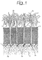
- the present invention relates to synthetic-grass structures of the type comprising a substrate with a plurality of filiform formations that extend upwards starting from the substrate itself so as to simulate natural-grass cover or natural turf.
- Synthetic grass structures of the type described above can be used both as products in themselves and in structures where, between the filiform formations that simulate natural-grass cover, there is dispersed a particulate filling material designed to maintain the filiform formations themselves in a substantially upright condition.
- the particulate filling material, or infill is made up of a substantially homogeneous mass of granular plastic material.
- the synthetic-grass structures considered previously are increasingly considered as being a valid alternative to natural-grass cover.
- This in particular, as regards applications in which, for different reasons (environmental conditions, intense use, etc.), upkeep of natural turf proves to be a critical problem, also as regards the maintenance costs involved.
- grass structures of the type described for making sports fields such as football fields, five-a-side football fields, American-football fields, and tennis courts.
- the use of grass structures of this type is also envisaged for providing athletics tracks.
- the synthetic grass In the first place, it is desirable for the synthetic grass to present an appearance as close as possible to the appearance of a natural-grass cover or natural turf. In other words, it is desirable that a synthetic-grass cover should not reveal too evidently its nature. For this reason, after the synthetic-grass flooring has been laid, it is frequently treated by direct brushing aimed at breaking up in the sense of a general fibrillation the filiform formations of the substrate so as to render them as far as possible similar to blades of natural grass.
- the solution of making the synthetic grass using filiform formations previously subjected to a treatment of curling or texturing (according to a term currently used in the sector of textile yarns) has been proposed and adopted in practice.
- a second category of factors that must be taken into account is linked to the wear of the synthetic-grass cover during use.
- synthetic-grass floorings tend to wear out (or, at the very least, to undergo serious alterations) in a far from uniform way according to the different conditions of use and the stresses to which different areas of the flooring may be subjected.
- the central area of the pitch and the areas around the goal-mouth tend to undergo greater stresses and hence to wear out to a more marked extent than do the other areas such as the areas located near to the corners of the pitch or the areas immediately at the sides of the goals.
- the purpose of the present invention is to provide a solution capable of overcoming, in a decisive way, the critical problems outlined above.
- the invention also refers to a corresponding synthetic-grass cover.
- the solution according to the invention makes it possible to provide a synthetic-grass covering which (both in the case where use of an infill is envisaged and in the case where use of said material is not envisaged) presents an appearance very similar to that of natural-grass cover, without requiring accessory treatment such as combing or fibrillation, as referred to previously.
- the solution according to the invention makes it possible to provide a synthetic-grass covering which is characterized by an excellent resistance to mechanical loads, above all as regards mechanical loads exerted by treading, to which a synthetic-grass flooring is subjected in particular when used for sports events.
- the solution according to the invention enables the filiform formations designed to simulate natural-grass cover to provide an action of containment or of retention of the particulate infill.
- the solution according to the invention enables "sowing" of the substrate with particulate infill when the synthetic flooring is being manufactured, consequently before proceeding to laying the synthetic-grass flooring itself.
- the solution according to the invention makes it possible to provide already at the level of the manufacturing process, hence in the factory a synthetic-grass flooring which comprises both the sheet substrate with the filiform formations designed to simulate natural turf and the particulate infill dispersed between the filiform formations themselves in a substantially upright condition.
- the operation of "sowing" the particulate material carried out at the level of the manufacturing process may be done in a more precise and more controlled way than can be achieved via in-field "sowing” after laying of the sheet substrate with the filiform formations.
- the solution according to the invention makes it possible to obtain - as product leaving the factory - a synthetic-grass flooring which comprises both the sheet substrate with the filiform formations and the particulate infill dispersed amongst the filiform formations, it being possible for the said synthetic-grass flooring to be made in the form of sheets possibly wound in rolls.
- a synthetic-grass flooring comprising a sheet substrate 1 designed to be laid on a subfloor G, which, in the most typical condition of use, consists of a subfloor made of tamped earth or of a bituminous mat, over which the synthetic-grass cover is laid usually in free-laying conditions.
- the sheet substrate 1 may be made up of a sheet of plastic material, such as a non-woven fabric, rubber-backed with the application, for example, of latexes, such as SBR or polyurethane latexes.
- a layer of foamed material for example a polyurethane-based foam material.
- a plurality of filiform formations 2 extend upwards, the said filiform formations being usually arranged in tufts so as to resemble more closely the blades of grass of natural-grass cover.
- the filiform formations 2 are anchored to the substrate 1 at their proximal ends, designated by 2a, and extend upwards with their distal ends for a total length measured starting from the general plane of extension of the substrate 1 which may typically be in the 10-mm to 80-mm range, according to the applications envisaged.
- the quantitative data given above have, of course, a purely indicative nature.
- the distal ends 2b instead of presenting an overall rectilinear pattern, the distal ends 2b have a twisted or "curly" pattern.
- the filiform formations 2 are ordered into tufts that present a general conformation that could be defined as "tree-like".
- the general criteria for making the substrate 2 and the filiform formations 2 are known to the art, and hence do not require a detailed description herein, also because they are of themselves not important for the purposes of understanding the present invention.
- the orientation is towards polyolefin materials, such as polyethylenes or polypropylene, or, more in general, any plastic material that can undergo processes of extrusion, spinning and/or drawing, so as to give rise to filaments capable of simulating the appearance of blades of grass of natural sward.
- the materials referred to above are, moreover, usually characterized by the fact that they can be pigmented relatively easily using pigments that can be introduced into the material for forming the filiform formations in order to give rise to a bulk colouring, which is maintained in a practically constant way even after a prolonged use of the synthetic-grass flooring.
- the absolute and relative dimensions of the filiform formations 2, measured in the direction orthogonal to the plane of extension of the substrate 1, are not in themselves of particularly critical importance as regards the implementation of the invention.
- the choice of particular dimensional values, whether absolute ones or relative ones, is thus determined principally by the purpose to which the flooring in question is to be put.
- a particulate or granular material (the two terms “particulate” and “granular” being used herein as synonyms), which functions as a filling material or infill 3.
- the function of the material 3 is basically that of keeping the filiform formations 2 in the upright condition, i.e., preventing them from undesirably lying down flat on the substrate 1.
- the particulate material 3 is dispersed amongst the filiform formations 2 in a sufficient amount to enable the filiform formations 2 to be supported by the infill 3 practically for the entire extent of the rectilinear portion of the bushy structure.
- the particulate infill material 3 is a substantially homogeneous material dispersed on top of the substrate 1 and amongst the filiform formations 2 in a substantially uniform way, without giving rise to superimposed layers having markedly different characteristics.
- the aforesaid particulate material is a granular material with a grain size of less than 5 mm, ranging typically between 0.5 and 4.5 mm, and more preferably still between 0.5 and 3 mm, with a density ranging typically between 0.9 and 1.6 grams/cm 3 .
- the material of the infill layer may advantageously be a polyolefin material, such as polyethylene, and, even more preferably, a recycled polyolefin material, such as recycled polyethylene.
- the aforesaid material may consist of a vinyl polymer, and, even more preferably, of recycled vinyl polymer.
- the choice of the infill material 3, the modalities of distribution (thickness or depth of the infill layer 3, grain size of the material, etc.) chiefly determine the characteristics of hardness/compliance of the sward.
- the aforesaid characteristics of hardness/compliance of the synthetic-grass flooring may be identified in a quantitatively precise way by resorting to the elastic-impact test forming the subject of the DIN standard 18035/6.
- This standard together with the standard DIN 18032/2, enables definition of a parameter or coefficient known as KA (abbreviation of the German word "Kraftabbau").
- the coefficient KA basically corresponds to a characterization, in percentage terms, of the behaviour of a flooring subjected to the fall of a heavy object of normalized dimensions as compared to the behaviour manifested in regard to the same load by a rigid surface typically made of cement.
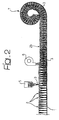
- FIG. 2 illustrates a process that can be adopted for making a synthetic-grass flooring of the type illustrated in Figure 1.
- the starting point of the process is represented by a sheet substrate 1 provided with a plurality of filiform formations 2 having a substantially rectilinear pattern, which extends from the substrate and is designed to simulate natural-grass cover or turf.
- the reference number 5 designates, as a whole, a machine (of a known type) designed for dispensing or laying on the starting material designated by 1, 2 a mass of filling material or infill 3 (of a type in itself known), consisting, for example, of a substantially homogeneous mass of a plastic material of the type already described previously.
- the aforesaid filling material or infill is dispersed amongst the filiform formations 2, so as to keep the filiform formations 2 in a substantially upright condition.
- the solution according to the invention is applicable also to synthetic-grass cover for which the distribution of an infill material 3 is not envisaged.
- the aforesaid operation of "sowing” or distribution of the particulate material can be performed, according to a solution currently adopted in the art, in field, i.e., after the substrate material 1, 2 has already been laid on the subfloor (designated by G in Figure 1), i.e., after the aforesaid substrate material 1, 2 has already been laid in the place of installation of the synthetic-grass flooring.
- the source 5 for delivering the starting material 1, 2 typically assumes the structure of a mobile dispensing unit designed to advance gradually over the substrate material 1, 2 to carry out the operation of "sowing" of the particulate material 3.
- a further unit (not illustrated in the drawings, but of a known type) basically configured as a rake or similar implement, the function of which is to pass in front of the dispensing unit 5 in the relative movement of advance with respect to the substrate material 1, 2, in such a way as to enable the substrate material 1, 2 to be pre-arranged in the most favourable conditions for receiving the granular material 3 by causing the filiform formations 2 - which, at the moment have a substantially rectilinear pattern - to be oriented substantially in a vertical direction, hence in a direction orthogonal to the general plane of extension of the substrate material 1.
- the operation of "sowing" the particulate material 3 can be performed in a particularly advantageous way, together with the operation of curling the filiform formations, which will be described in greater detail hereinafter, in an industrial environment, i.e., in the context of a single production line, where, starting from the substrate material 1, 2, a final material is obtained that comprises the aforesaid substrate material plus the particulate infill 3.
- a final material is obtained that comprises the aforesaid substrate material plus the particulate infill 3.
- both the criteria that determine the choice of the substrate material 1, 2 and the criteria for carrying out the operation of sowing the particulate material 3 correspond to solutions which are in themselves known and hence do not constitute a specific subject of the present application.
- the aforesaid result is obtained by applying a flow of heated aeriform substance.
- the said flow of aeriform substance may be simply a flow of heated air generated by a pumping element 6 basically consisting of a fan with associated thereto a heating source. It may typically be represented by an industrial fan-heater or, possibly, a heating source obtained by modifying a gun-type heating apparatus, such as a blow-torch of the sort currently used, for example, by persons who install waterproof sheeting.
- the operation of directing a flow of heated air onto the distal portions 2b of the filiform formations 2 in order to cause the said distal portions, which preferably consist of thermoplastic material, such as polyolefin material, to curl may be performed even after the synthetic-grass flooring has been laid. This is done typically after sowing of the particulate material 3 (if envisaged).
- the aforesaid polyolefin material may be chosen in the category of the materials already currently in use for making synthetic-grass structures. For instance, it may be polyethylene (with a softening temperature in the region of 70-100°C according to the density), polypropylene (with a softening temperature in the region of 130-160°C, once again according to the density), or else copolymers of various nature (with softening temperatures usually comprised within the extreme limits defined above).
- the above applies, in particular, as regards the choice and maintenance of conditions of strict tolerance in regulating parameters, such as the temperature and flow rate of the aeriform substance, the distance between the source 6 and the synthetic-grass structure that undergoes the curling treatment, etc.
- the above are, in fact, parameters which, according to the characteristics of the filiform formations 2 (their length, in particular as regards the length of the portion that projects above the mass of infill 3, the material constituting the filiform formations, and the dimensions of the filiform formations) determine the degree of curling bestowed upon the distal portions 2b of the filiform formations 2.
- the degree of the phenomenon of curling induced on the distal ends 2b of the filiform formations 2 depends, all other parameters being equal (dimensions of the filiform formations, constituent material, temperature of the flow of aeriform substance, etc.), upon the relative rate of feed of the treated web-like material with respect to the heating source 6.
- an important characteristic of the solution according to the invention which is linked to the general bushy shaping attributed to the filiform formations 2 by subjecting their distal ends 2b to curling, is provided by the fact that, once the particulate infill 3 has been sown amongst the filiform formations 2 which are then subjected to curling at their top ends 2b, it is, so to speak, trapped between the sheet substrate 1 and the intertwined curly ends 2b of the filiform formations 2.
- the above result may be rendered even more evident in the case where the particulate material is in some way rendered at least slightly cohesive, for example by the addition of a bonding agent or by subjecting the layer of particulate material 3, once sown, to a treatment of contained compression.
- the product coming out of the curling station 6 of Figure 2 constitutes, to all effects and purposes, a complete synthetic-grass covering that can be made in the form of sheets or strips which can then possibly be wound in the form of rolls, as is schematically indicated by the reference number 7 in Figure 2.
- the material in rolls thus obtained can be stored in view of a subsequent delivery to the place where it is to be laid.
Abstract
Description
- The present invention relates to synthetic-grass structures of the type comprising a substrate with a plurality of filiform formations that extend upwards starting from the substrate itself so as to simulate natural-grass cover or natural turf. Synthetic grass structures of the type described above can be used both as products in themselves and in structures where, between the filiform formations that simulate natural-grass cover, there is dispersed a particulate filling material designed to maintain the filiform formations themselves in a substantially upright condition.
- Solutions of this sort are described, for example, in US-A-5 958 527 or EP-A-1 158 099. In particular, in the solution described in the latter document, the particulate filling material, or infill, is made up of a substantially homogeneous mass of granular plastic material.
- The synthetic-grass structures considered previously (whether these be solutions that do not envisage the use of filling material (infill), or and above all solutions that do envisage the use of the aforesaid infill) are increasingly considered as being a valid alternative to natural-grass cover. This, in particular, as regards applications in which, for different reasons (environmental conditions, intense use, etc.), upkeep of natural turf proves to be a critical problem, also as regards the maintenance costs involved. For example, there is known the use of grass structures of the type described for making sports fields such as football fields, five-a-side football fields, American-football fields, and tennis courts. The use of grass structures of this type is also envisaged for providing athletics tracks.
- With a certain degree of approximation, but with substantial adherence to reality, in making and laying synthetic-grass floorings of the type described, it is necessary to take into account at least three basic categories of factors.
- In the first place, it is desirable for the synthetic grass to present an appearance as close as possible to the appearance of a natural-grass cover or natural turf. In other words, it is desirable that a synthetic-grass cover should not reveal too evidently its nature. For this reason, after the synthetic-grass flooring has been laid, it is frequently treated by direct brushing aimed at breaking up in the sense of a general fibrillation the filiform formations of the substrate so as to render them as far as possible similar to blades of natural grass. Once again with the same aim in view, the solution of making the synthetic grass using filiform formations previously subjected to a treatment of curling or texturing (according to a term currently used in the sector of textile yarns) has been proposed and adopted in practice. This solution, however, comes up against two sorts of difficulties. On the one hand, in fact, in order to make a sheet substrate with a plurality of filiform formations extending from the substrate using a curled or textured yarn raises a great deal of difficulties of a technological nature. In the second place, a substrate of this type cannot practically be used in combination with an infill given that it is very difficult and, in effect, impossible to "sow" the infill into the dense network constituted by the curly or textured filiform formations.
- A second category of factors that must be taken into account is linked to the wear of the synthetic-grass cover during use. In the absence, in fact, of the mechanism of regrowth of natural-grass cover, synthetic-grass floorings tend to wear out (or, at the very least, to undergo serious alterations) in a far from uniform way according to the different conditions of use and the stresses to which different areas of the flooring may be subjected. In order to provide an example that is immediately understandable, it may readily be appreciated that, in the case of a flooring for playing football, the central area of the pitch and the areas around the goal-mouth tend to undergo greater stresses and hence to wear out to a more marked extent than do the other areas such as the areas located near to the corners of the pitch or the areas immediately at the sides of the goals. In the case of synthetic-grass cover where infill is used, it is necessary to take into consideration that some types of stresses may lead the infill to be knocked out of the place where it is located. As a typical example, the case of an athlete may be considered who is wearing shoes with studs or spikes and who exploits the said studs or spikes to exert a strong thrust forwards or perform a sharp deceleration. Usually, the filiform formations of the grass cover do not provide an appreciable action of anchorage in regard to the infill when the infill is subjected to such intense stresses.
- Finally, a third set of factors to be taken into consideration is strictly linked to the laying of the synthetic-grass flooring. In particular, when synthetic-grass floorings are involved which envisage the use of infill, current practice is to lay first the sheet substrate provided with filiform formations simulating natural-grass cover and then to "sow" said cover with particulate infill.
- The above operation carried out "in field" is, of course, open to various critical factors. Just to mention a few examples, when "sowing" the particulate infill, it is usually preferable to intervene first on the filiform formations in such a way that, when they are sown with the infill, they are oriented in a substantially vertical direction. The purpose of this is to enable the particulate material to deposit gradually starting from the lowest level adjacent to the ground. Furthermore, exact dosage of the amount of particulate material deposited per unit surface requires the availability of special equipment and, in general, specialized staff. In the case where the infill material is a plastic polymer material, other factors may also be involved, such as ones linked to the temperature at which "sowing" of the infill is carried out.
- The purpose of the present invention is to provide a solution capable of overcoming, in a decisive way, the critical problems outlined above.
- In accordance with the present invention, the above purpose is achieved thanks to a process having the characteristics recalled specifically in the ensuing claims.
- The invention also refers to a corresponding synthetic-grass cover.
- In particular, the solution according to the invention makes it possible to provide a synthetic-grass covering which (both in the case where use of an infill is envisaged and in the case where use of said material is not envisaged) presents an appearance very similar to that of natural-grass cover, without requiring accessory treatment such as combing or fibrillation, as referred to previously.
- In the second place, the solution according to the invention makes it possible to provide a synthetic-grass covering which is characterized by an excellent resistance to mechanical loads, above all as regards mechanical loads exerted by treading, to which a synthetic-grass flooring is subjected in particular when used for sports events.
- Furthermore, in the implementation of synthetic-grass floorings which envisage the use of an infill, the solution according to the invention enables the filiform formations designed to simulate natural-grass cover to provide an action of containment or of retention of the particulate infill.
- The above factor proves of importance for at least two basic reasons.
- In the first place, the incidence of phenomena linked to the possible uprooting of the infill as a result of mechanical stresses, such as those due to the loads applied by an athlete wearing footwear provided with studs or spikes, is considerably reduced, if not virtually eliminated.
- What is more, the solution according to the invention enables "sowing" of the substrate with particulate infill when the synthetic flooring is being manufactured, consequently before proceeding to laying the synthetic-grass flooring itself. The solution according to the invention makes it possible to provide already at the level of the manufacturing process, hence in the factory a synthetic-grass flooring which comprises both the sheet substrate with the filiform formations designed to simulate natural turf and the particulate infill dispersed between the filiform formations themselves in a substantially upright condition. The operation of "sowing" the particulate material carried out at the level of the manufacturing process may be done in a more precise and more controlled way than can be achieved via in-field "sowing" after laying of the sheet substrate with the filiform formations.
- Specifically, the solution according to the invention makes it possible to obtain - as product leaving the factory - a synthetic-grass flooring which comprises both the sheet substrate with the filiform formations and the particulate infill dispersed amongst the filiform formations, it being possible for the said synthetic-grass flooring to be made in the form of sheets possibly wound in rolls.
- The operation of laying the synthetic-grass flooring is consequently considerably simplified, in so far as it amounts to the operation of unrolling and laying the said synthetic-grass flooring on the ground, without any need to perform further operations. In carrying out the above laying operation, it is possible to rely upon a synthetic-grass flooring which, since it has been completely made in an industrial context, benefits from the fact that it must meet standards of production and of quality that are difficult to achieve, if not downright impossible to achieve, with a laying process of a traditional type.
- The present invention will now be described, purely by way of non-limiting example, with reference to the attached drawings, in which:
- Figure 1 reproduces schematically an idealized vertical section of a synthetic-grass structure according to the invention; and
- Figure 2 illustrates an example of a process for making the synthetic-grass structure illustrated in Figure 1.
- Illustrated in Figure 1 is a synthetic-grass flooring comprising a
sheet substrate 1 designed to be laid on a subfloor G, which, in the most typical condition of use, consists of a subfloor made of tamped earth or of a bituminous mat, over which the synthetic-grass cover is laid usually in free-laying conditions. - The
sheet substrate 1 may be made up of a sheet of plastic material, such as a non-woven fabric, rubber-backed with the application, for example, of latexes, such as SBR or polyurethane latexes. To the substrate in question, there may advantageously be associated, on the side designed to face the subfloor G, a layer of foamed material, for example a polyurethane-based foam material. - Starting from the
substrate 1, a plurality offiliform formations 2 extend upwards, the said filiform formations being usually arranged in tufts so as to resemble more closely the blades of grass of natural-grass cover. - The
filiform formations 2 are anchored to thesubstrate 1 at their proximal ends, designated by 2a, and extend upwards with their distal ends for a total length measured starting from the general plane of extension of thesubstrate 1 which may typically be in the 10-mm to 80-mm range, according to the applications envisaged. The quantitative data given above have, of course, a purely indicative nature. - According to an important characteristic of the invention, which will be illustrated in greater detail in what follows, instead of presenting an overall rectilinear pattern, the
distal ends 2b have a twisted or "curly" pattern. - Consequently, the
filiform formations 2 are ordered into tufts that present a general conformation that could be defined as "tree-like". - The aforesaid "tree-like" formations may, therefore, be distinguished into:
- a stem or trunk part adjacent to the
proximal end 2a and following an overall rectilinear pattern; and - a top part, which defines the
distal end 2b having a curly pattern, as mentioned previously. - Except for the appearance of the
distal ends 2b, an appearance to which we shall return later, the general criteria for making thesubstrate 2 and the filiform formations 2 (including the modalities for obtaining firm anchorage of theproximal ends 2a of thefiliform formations 2 to the substrate 1) are known to the art, and hence do not require a detailed description herein, also because they are of themselves not important for the purposes of understanding the present invention. - As regards the choice of material constituting the
filiform formations 2, the orientation is towards polyolefin materials, such as polyethylenes or polypropylene, or, more in general, any plastic material that can undergo processes of extrusion, spinning and/or drawing, so as to give rise to filaments capable of simulating the appearance of blades of grass of natural sward. - The materials referred to above are, moreover, usually characterized by the fact that they can be pigmented relatively easily using pigments that can be introduced into the material for forming the filiform formations in order to give rise to a bulk colouring, which is maintained in a practically constant way even after a prolonged use of the synthetic-grass flooring.
- In general, apart form the overall "tree-like" configuration, the absolute and relative dimensions of the
filiform formations 2, measured in the direction orthogonal to the plane of extension of thesubstrate 1, are not in themselves of particularly critical importance as regards the implementation of the invention. The choice of particular dimensional values, whether absolute ones or relative ones, is thus determined principally by the purpose to which the flooring in question is to be put. - Purely by way of indicative example, as regards applications in the sector of sports facilities, use of the said synthetic-grass flooring for tennis courts will thus tend to privilege embodiments with thin sward, whereas in the case of soccer pitches or American-football pitches, the choice will preferably favour embodiments with thicker sward.
- In the exemplary embodiment of the invention illustrated herein (which, it is recalled, is provided purely by way of example) on top of the
substrate 1, and hence amongst thefiliform formations 2, there is dispersed a particulate or granular material (the two terms "particulate" and "granular" being used herein as synonyms), which functions as a filling material or infill 3. The function of the material 3 is basically that of keeping thefiliform formations 2 in the upright condition, i.e., preventing them from undesirably lying down flat on thesubstrate 1. - Once again it is emphasized that the invention is in itself applicable also to the implementation of synthetic-grass floorings in which the use of the particulate material 3 is not contemplated, and consequently grass floorings made up basically only of the
substrate 1 and thefiliform formations 2. - If present, the particulate material 3 is dispersed amongst the
filiform formations 2 in a sufficient amount to enable thefiliform formations 2 to be supported by the infill 3 practically for the entire extent of the rectilinear portion of the bushy structure. - Preferably, the particulate infill material 3 is a substantially homogeneous material dispersed on top of the
substrate 1 and amongst thefiliform formations 2 in a substantially uniform way, without giving rise to superimposed layers having markedly different characteristics. - In the currently preferred embodiment of the invention, the aforesaid particulate material is a granular material with a grain size of less than 5 mm, ranging typically between 0.5 and 4.5 mm, and more preferably still between 0.5 and 3 mm, with a density ranging typically between 0.9 and 1.6 grams/cm3.
- According to criteria that are, on the other hand, already known from EP-A-1 158 099, the material of the infill layer may advantageously be a polyolefin material, such as polyethylene, and, even more preferably, a recycled polyolefin material, such as recycled polyethylene.
- As variant, the aforesaid material may consist of a vinyl polymer, and, even more preferably, of recycled vinyl polymer.
- The choice of the infill material 3, the modalities of distribution (thickness or depth of the infill layer 3, grain size of the material, etc.) chiefly determine the characteristics of hardness/compliance of the sward. As in the case of other types of flooring and, in particular, floorings designed for use in sports facilities, the aforesaid characteristics of hardness/compliance of the synthetic-grass flooring may be identified in a quantitatively precise way by resorting to the elastic-impact test forming the subject of the DIN standard 18035/6. This standard, together with the standard DIN 18032/2, enables definition of a parameter or coefficient known as KA (abbreviation of the German word "Kraftabbau").
- The coefficient KA basically corresponds to a characterization, in percentage terms, of the behaviour of a flooring subjected to the fall of a heavy object of normalized dimensions as compared to the behaviour manifested in regard to the same load by a rigid surface typically made of cement.
- In any case, the specific criteria that enable a synthetic-grass structure, such as the one illustrated in the drawings, to have a given value of the coefficient KA does not constitute a specific subject of the present patent application; consequently, a detailed description of the said criteria will not be provided herein.
- The diagram of Figure 2 illustrates a process that can be adopted for making a synthetic-grass flooring of the type illustrated in Figure 1.
- The starting point of the process is represented by a
sheet substrate 1 provided with a plurality offiliform formations 2 having a substantially rectilinear pattern, which extends from the substrate and is designed to simulate natural-grass cover or turf. - Starting
materials - The reference number 5 designates, as a whole, a machine (of a known type) designed for dispensing or laying on the starting material designated by 1, 2 a mass of filling material or infill 3 (of a type in itself known), consisting, for example, of a substantially homogeneous mass of a plastic material of the type already described previously. The aforesaid filling material or infill is dispersed amongst the
filiform formations 2, so as to keep thefiliform formations 2 in a substantially upright condition. - As far as laying or "sowing" of the particulate material 3 is concerned, various considerations must be taken into account.
- In the first place, as has already been said repeatedly herein, the solution according to the invention is applicable also to synthetic-grass cover for which the distribution of an infill material 3 is not envisaged.
- In the second place, the aforesaid operation of "sowing" or distribution of the particulate material can be performed, according to a solution currently adopted in the art, in field, i.e., after the
substrate material aforesaid substrate material material substrate material - Associated to the dispensing unit 5 there may be a further unit (not illustrated in the drawings, but of a known type) basically configured as a rake or similar implement, the function of which is to pass in front of the dispensing unit 5 in the relative movement of advance with respect to the
substrate material substrate material substrate material 1. - However, the operation of "sowing" the particulate material 3 can be performed in a particularly advantageous way, together with the operation of curling the filiform formations, which will be described in greater detail hereinafter, in an industrial environment, i.e., in the context of a single production line, where, starting from the
substrate material - As has already been said previously, both the criteria that determine the choice of the
substrate material - After completing the operation of "sowing" the particulate material 3 and, consequently, after providing a structure that can basically be likened, for instance, to the one described in EP-A-1 158 099, according to an important feature of the present invention, an operation of curling or "texturing" the
distal parts 2b of thefiliform formations 2 is carried out. The aim of the above is to bestow upon the filiform formations the general tree-like appearance illustrated in Figure 1. - In the currently preferred embodiment of the invention, the aforesaid result is obtained by applying a flow of heated aeriform substance. The said flow of aeriform substance may be simply a flow of heated air generated by a
pumping element 6 basically consisting of a fan with associated thereto a heating source. It may typically be represented by an industrial fan-heater or, possibly, a heating source obtained by modifying a gun-type heating apparatus, such as a blow-torch of the sort currently used, for example, by persons who install waterproof sheeting. - As has already been said previously, the operation of directing a flow of heated air onto the
distal portions 2b of thefiliform formations 2 in order to cause the said distal portions, which preferably consist of thermoplastic material, such as polyolefin material, to curl may be performed even after the synthetic-grass flooring has been laid. This is done typically after sowing of the particulate material 3 (if envisaged). - The aforesaid polyolefin material may be chosen in the category of the materials already currently in use for making synthetic-grass structures. For instance, it may be polyethylene (with a softening temperature in the region of 70-100°C according to the density), polypropylene (with a softening temperature in the region of 130-160°C, once again according to the density), or else copolymers of various nature (with softening temperatures usually comprised within the extreme limits defined above).
- It will moreover be appreciated that carrying out the operation of heating in the context of the production line of an industrial plant, and hence on line, usually after the operation of sowing of the particulate material 3 proves advantageous for various reasons.
- The above applies, in particular, as regards the choice and maintenance of conditions of strict tolerance in regulating parameters, such as the temperature and flow rate of the aeriform substance, the distance between the
source 6 and the synthetic-grass structure that undergoes the curling treatment, etc. The above are, in fact, parameters which, according to the characteristics of the filiform formations 2 (their length, in particular as regards the length of the portion that projects above the mass of infill 3, the material constituting the filiform formations, and the dimensions of the filiform formations) determine the degree of curling bestowed upon thedistal portions 2b of thefiliform formations 2. - The choice of using, as heating source, a fan-heater or a similar device constitutes just one of the possible choices for achieving the described result.
- The use of a fan-heater is currently considered preferential. There is, in fact, reason to believe that the turbulent flow of air induced upon the synthetic-grass structure has a beneficial effect in facilitating curling of the filiform formations. As an alternative, it is possible to consider static heating sources, such as, for instance, infrared lamps or other sources of heating by irradiation.
- When a fan-heater is used as
heating source 6, the degree of the phenomenon of curling induced on the distal ends 2b of thefiliform formations 2 depends, all other parameters being equal (dimensions of the filiform formations, constituent material, temperature of the flow of aeriform substance, etc.), upon the relative rate of feed of the treated web-like material with respect to theheating source 6. - By adjusting the above parameter (of course, jointly with the other parameters referred to previously), it is thus possible to regulate the degree of curling achieved in a very precise way.
- In this connection, different choices may be made depending upon the applicational requirements.
- For instance, for applications such as tennis courts, it is usually preferable to obtain a rather high degree of curling, so as to give rise, at the top surface of the synthetic-grass cover, to a rather compact intertwining of curly fibres.
- In other applications, such as soccer fields or American-football fields, a smaller degree of curling is usually preferred.
- Tests so far carried out by the present applicant show that it may be advantageous not to push the heat treatment up to the point of obtaining a connection due to melting between adjacent filiform formations.
- Instead, in applications where it is desired to obtain a top surface of the grass cover that is rather compact, it may be advantageous to protract heat treatment up to the point of obtaining an at least marginal connection between adjacent filiform formations.
- Without wishing to be tied down to any specific theory in this connection, the applicant has reasons to believe that the excellent qualities of resistance to wear revealed by a synthetic-grass flooring made according to the invention are provided by the fact that, instead of standing upright in a substantially vertical direction, the distal ends 2b of the
filiform formations 2 as a whole lie flat, at least for part of their length in the direction of extension of the synthetic-grass flooring - The above means that the loads applied by treading do not result in violent shearing stresses, but assume, instead, the character of a compressive and/or flexural stressing of the intertwined curly ends.
- When the embodiment of the synthetic-grass flooring envisages the use of the infill, an important characteristic of the solution according to the invention, which is linked to the general bushy shaping attributed to the
filiform formations 2 by subjecting theirdistal ends 2b to curling, is provided by the fact that, once the particulate infill 3 has been sown amongst thefiliform formations 2 which are then subjected to curling at theirtop ends 2b, it is, so to speak, trapped between thesheet substrate 1 and the intertwined curly ends 2b of thefiliform formations 2. - The above result, which is, however, beneficial when sowing of the particulate material 3 and curling of the top ends of the
filiform formations 2 are performed in field, i.e., after laying of the synthetic-grass flooring, is of determining importance when, in the currently preferred embodiment, the aforesaid operations of sowing and curling of the filiform formations are carried out in the context of an industrial plant. - Since the particulate material 3 is trapped up against the
sheet substrate 1, the product leaving the workstation, where the operation of curling (indicated by 6 in Figure 2) can be handled without risk of the particulate material 3 separating from the product thus obtained and hence being dispersed. - The above result may be rendered even more evident in the case where the particulate material is in some way rendered at least slightly cohesive, for example by the addition of a bonding agent or by subjecting the layer of particulate material 3, once sown, to a treatment of contained compression.
- The product coming out of the curling
station 6 of Figure 2 constitutes, to all effects and purposes, a complete synthetic-grass covering that can be made in the form of sheets or strips which can then possibly be wound in the form of rolls, as is schematically indicated by the reference number 7 in Figure 2. - The material in rolls thus obtained can be stored in view of a subsequent delivery to the place where it is to be laid.
- In order to lay the synthetic-grass flooring, it is sufficient to unroll the material onto the subfloor, which is pre-arranged for this purpose, without having to carry out in field either the operation of sowing the infill 3 or the operation of curling of the top or distal ends of the
filiform formations 2. Allied to the above is the advantage of having available a material which, having been made completely in the factory, presents given characteristics that are altogether precise and reliable. - Of course, without prejudice to the principle of the invention, the details of construction and the embodiments may vary widely with respect to what is described and illustrated herein, without thereby departing from the scope of the present invention as defined in the ensuing claims.
Claims (31)
- A process for making a synthetic-grass covering, comprising the operation of providing a substrate (1) with a plurality of filiform formations (2) that extend from the substrate (1) to simulate natural-grass cover or sward, said filiform formations (2) being provided with respective proximal ends (2a) and distal ends (2b) with respect to the substrate,
characterized in that it comprises the operation of subjecting said distal ends (2b) to curling, bestowing upon said filiform formations (2) a general tree-like conformation. - The process according to Claim 1, characterized in that said operation of curling is carried out by application of heat (6) on said distal ends (2b) of said filiform formations (2).
- The process according to Claim 2, characterized in that it comprises the operation of providing said application of heat by means of a flow of a heated aeriform substance (6).
- The process according to any one of the preceding claims, characterized in that said distal ends (2b) of said filiform formations (2) undergo curling after the synthetic-grass flooring has been laid.
- The process according to any one of the preceding claims, characterized in that said distal ends (2b) of said filiform formations (2) undergo curling before the synthetic-grass flooring has been laid.
- The process according to any one of the preceding claims, characterized in that it further comprises the operation of dispersing a particulate filling material or infill (3) amongst said filiform formations (2) so as to maintain the latter in substantially upright conditions.
- The process according to Claim 6, characterized in that it comprises the operation of dispersing said particulate infill (3) amongst said filiform formations (2) before subjecting said distal ends (2b) of said filiform formations (2) to curling.
- The process according to any one of the preceding claims, characterized in that it comprises the operation of making said filiform formations (2) starting from a polyolefin material.
- The process according to any one of the preceding claims, characterized in that it comprises the operation of making said filiform formations (2a) starting from a bulk-pigmented material.
- The process according to any one of the preceding claims, characterized in that said treatment of curling said distal ends (2b) of said filiform formations (2) is performed, preventing the setting-up of points of connection between distal ends associated to different filiform formations.
- The process according to any one of the preceding Claims 1 to 9, characterized in that said treatment of curling said distal ends (2b) of said filiform formations (2) is performed causing the at least marginal connection between distal ends associated to different filiform formations.
- The process according to Claim 6, characterized in that it comprises the operation of rendering at least partially cohesive said particulate infill (3).
- The process according to Claim 12,
characterized in that said particulate infill (3) is rendered at least partially cohesive by the addition of a bonding agent. - The process according to Claim 12, characterized in that said particulate infill (3) is rendered at least partially cohesive by a treatment of compacting.
- The process according to Claim 6, characterized in that said operation of dispersing a particulate filling material or infill (3) and said subsequent treatment of curling of the distal ends (2b) of said filiform formations (2) are performed as successive steps of an industrial manufacturing process.
- The process according to Claim 15, characterized in that it comprises the operation of winding (7) said synthetic-grass flooring comprising said particulate infill (3) withheld on said substrate by said tree-shaped filiform formations (2) in the form of a material wound in rolls.
- A synthetic-grass flooring comprising a substrate (1) with a plurality of filiform formations (2) extending from the substrate for simulating the natural turf or sward, said filiform formations (2) being provided with respective basically rectilinear proximal ends (2a) and respective distal ends (2b),
characterized in that said distal ends (2b) are substantially curly, so that said filiform formations (2) have a general tree-like conformation. - The synthetic-grass flooring according to Claim 17, characterized in that said filiform formations (2) are made of thermoplastic material and said distal ends (2b) of said filiform formations (2) are curly on account of thermal deformation.
- The synthetic-grass flooring according to either one of the preceding Claims 17 and 18, characterized in that said distal ends (2b) of said filiform formations (2) are made of material rendered curly after laying of said synthetic-grass flooring.
- The synthetic-grass flooring according to either one of the preceding Claims 17 and 18, characterized in that said distal ends (2b) of said filiform formations (2) are made of material subjected to curling before laying of said synthetic-grass flooring.
- The synthetic-grass flooring according to any one of the preceding Claims 17 to 20, characterized in that it comprises a particulate infill (3), dispersed amongst said filiform formations (2) so as to maintain said filiform formations (2) in a substantially upright condition.
- The synthetic-grass flooring according to Claim 21, characterized in that said particulate infill (3) is a material dispersed amongst said filiform formations (2) before said distal ends (2b) of said filiform formations (2) are subjected to curling.
- The synthetic-grass flooring according to any one of the preceding Claims 17 to 22, characterized in that said filiform formations (2) are made of a polyolefin material.
- The synthetic-grass flooring according to any one of the preceding Claims 17 to 23, characterized in that said filiform formations (2) are made of a bulk-pigmented material.
- The synthetic-grass flooring according to any one of the preceding Claims 17 to 24, characterized in that said distal ends (2b) of said filiform formations (2) are subjected to curling in the absence of points of connection between distal ends associated to different filiform formations.
- The synthetic-grass flooring according to any one of the preceding Claims 17 to 24, characterized in that said distal ends (2b) of said filiform formations (2) are subjected to curling in the presence of at least marginal points of connection between distal ends associated to different filiform formations.
- The synthetic-grass flooring according to Claim 21, characterized in that said particulate infill (3) is at least partially cohesive.
- The synthetic-grass flooring according to Claim 27, characterized in that said particulate infill (3) contains an added bonding agent.
- The synthetic-grass flooring according to Claim 27 or Claim 28, characterized in that said particulate infill (3) is a material subjected to compacting.
- The synthetic-grass flooring according to Claim 21, in the form of the finished product of an industrial manufacturing process comprising said infill (3) withheld on said substrate (1) by said curly distal ends (2b) of said filiform formations (2).
- The synthetic-grass flooring according to Claim 30, in the form of a sheet or strip material wound in rolls pre-arranged for laying on a subfloor (G).
Priority Applications (8)
| Application Number | Priority Date | Filing Date | Title |
|---|---|---|---|
| EP20020425398 EP1375750B1 (en) | 2002-06-17 | 2002-06-17 | A process for producing synthetic-grass structures and corresponding synthetic-grass structure |
| PT02425398T PT1375750E (en) | 2002-06-17 | 2002-06-17 | A process for producing synthetic-grass structures and corresponding synthetic-grass structure |
| DK02425398T DK1375750T3 (en) | 2002-06-17 | 2002-06-17 | Method of producing artificial grass structures and corresponding artificial grass structures |
| ES02425398T ES2330310T3 (en) | 2002-06-17 | 2002-06-17 | PROCESS FOR MANUFACTURING SYNTHETIC LAWN STRUCTURES AND CORRESPONDING SYNTHETIC LAWN STRUCTURE. |
| DE60233039T DE60233039D1 (en) | 2002-06-17 | 2002-06-17 | Process for the production of synthetic grass structures, and synthetic grass structure |
| AT02425398T ATE437269T1 (en) | 2002-06-17 | 2002-06-17 | METHOD FOR PRODUCING SYNTHETIC GRASS STRUCTURES, AND SYNTHETIC GRASS STRUCTURE |
| CA 2430756 CA2430756A1 (en) | 2002-06-17 | 2003-05-30 | A process for producing synthetic-grass structures and corresponding synthetic-grass structure |
| US10/460,549 US7264854B2 (en) | 2002-06-17 | 2003-06-11 | Process for producing synthetic-grass structures and corresponding synthetic-grass structure |
Applications Claiming Priority (1)
| Application Number | Priority Date | Filing Date | Title |
|---|---|---|---|
| EP20020425398 EP1375750B1 (en) | 2002-06-17 | 2002-06-17 | A process for producing synthetic-grass structures and corresponding synthetic-grass structure |
Publications (2)
| Publication Number | Publication Date |
|---|---|
| EP1375750A1 true EP1375750A1 (en) | 2004-01-02 |
| EP1375750B1 EP1375750B1 (en) | 2009-07-22 |
Family
ID=29717012
Family Applications (1)
| Application Number | Title | Priority Date | Filing Date |
|---|---|---|---|
| EP20020425398 Expired - Lifetime EP1375750B1 (en) | 2002-06-17 | 2002-06-17 | A process for producing synthetic-grass structures and corresponding synthetic-grass structure |
Country Status (8)
| Country | Link |
|---|---|
| US (1) | US7264854B2 (en) |
| EP (1) | EP1375750B1 (en) |
| AT (1) | ATE437269T1 (en) |
| CA (1) | CA2430756A1 (en) |
| DE (1) | DE60233039D1 (en) |
| DK (1) | DK1375750T3 (en) |
| ES (1) | ES2330310T3 (en) |
| PT (1) | PT1375750E (en) |
Cited By (9)
| Publication number | Priority date | Publication date | Assignee | Title |
|---|---|---|---|---|
| WO2006023797A1 (en) * | 2004-08-20 | 2006-03-02 | Coevin Licensing, Llc | Roll up artificial turf |
| US7060334B2 (en) | 2003-06-10 | 2006-06-13 | Mondo S.P.A. | Infill material for synthetic-grass structures, corresponding synthetic-grass structure and process of preparation |
| US7585555B2 (en) | 2005-12-23 | 2009-09-08 | Mondo S.P.A. | Synthetic-grass flooring and method for laying same |
| US7648420B2 (en) | 2004-11-18 | 2010-01-19 | Mondo S.P.A. | Multi-purpose sports facility |
| EP2206833A1 (en) | 2009-01-12 | 2010-07-14 | Mondo S.p.A. | A method of producing an infill material for synthetic-grass structures, corresponding material, and synthetic grass structure |
| US7814728B2 (en) | 2005-09-22 | 2010-10-19 | Mondo S.P.A. | Flooring material, methods for producing and laying same |
| US8153227B2 (en) | 2007-07-06 | 2012-04-10 | Mondo S.P.A. | Substrate for floorings such as, for instance, synthetic grass turf, corresponding synthetic grass turf and methods of manufacture |
| CN1990956B (en) * | 2005-12-30 | 2012-05-09 | 曼顿有限公司 | Method for producing a yarn and synthetic grass structure produced using such a yarn |
| US8221856B2 (en) | 2005-05-27 | 2012-07-17 | Mondo S.P.A. | Synthetic grass structure |
Families Citing this family (14)
| Publication number | Priority date | Publication date | Assignee | Title |
|---|---|---|---|---|
| US8263203B2 (en) * | 2003-04-24 | 2012-09-11 | Usgreentech, L.L.C. | Filler for artificial turf system |
| US20080124496A1 (en) * | 2003-12-10 | 2008-05-29 | Textile Management Associates, Inc. | Artificial turf with granule retaining fibers |
| US20080125237A1 (en) * | 2003-12-10 | 2008-05-29 | Textile Management Associates, Inc. | Golf mat |
| US7758281B2 (en) * | 2004-07-08 | 2010-07-20 | General Sports Venue Llc | Synthetic sports turf having improved playability and wearability |
| US20080268184A1 (en) * | 2007-04-30 | 2008-10-30 | Charles Cook | Synthetic sports turf having lowered infill levels |
| JP4502400B2 (en) * | 2007-12-27 | 2010-07-14 | 住友ゴム工業株式会社 | Artificial turf structure using an artificial turf filling granule and the artificial turf filling granule |
| US8359989B2 (en) | 2008-02-15 | 2013-01-29 | Card-Monroe Corp. | Stitch distribution control system for tufting machines |
| US8141505B2 (en) | 2008-02-15 | 2012-03-27 | Card-Monroe Corp. | Yarn color placement system |
| WO2010075098A1 (en) | 2008-12-15 | 2010-07-01 | Textile Management Associates, Inc. | Method of recycling synthetic turf and infill product |
| US9410026B1 (en) | 2009-05-22 | 2016-08-09 | Columbia Insurance Company | Rebond polyurethane foam comprising reclaimed carpet material and methods for the manufacture of same |
| US9724852B1 (en) | 2009-05-22 | 2017-08-08 | Columbia Insurance Company | High density composites comprising reclaimed carpet material |
| US11193225B2 (en) | 2016-03-17 | 2021-12-07 | Card-Monroe Corp. | Tufting machine and method of tufting |
| US10233578B2 (en) | 2016-03-17 | 2019-03-19 | Card-Monroe Corp. | Tufting machine and method of tufting |
| US11585029B2 (en) | 2021-02-16 | 2023-02-21 | Card-Monroe Corp. | Tufting maching and method of tufting |
Citations (6)
| Publication number | Priority date | Publication date | Assignee | Title |
|---|---|---|---|---|
| EP0259940A2 (en) * | 1986-09-12 | 1988-03-16 | Koninklijke Nijverdal-Ten Cate N.V. | Method of manufacturing an artificial grass and an artificial grass obtained therewith |
| EP0301843A1 (en) * | 1987-07-27 | 1989-02-01 | Bonar Textiles Limited | Mat and method of manufacture |
| JPH07158008A (en) * | 1993-12-07 | 1995-06-20 | Sekisui Chem Co Ltd | Artificial lawn |
| US5958527A (en) * | 1998-09-21 | 1999-09-28 | Fieldturf Holdings, Inc. | Process of laying synthetic grass |
| WO2001048322A1 (en) * | 1999-12-02 | 2001-07-05 | Hugo De Vries | Artificial turf including damping material |
| EP1158099A2 (en) * | 2000-05-25 | 2001-11-28 | Mondo S.p.A. | Synthetic-grass structure, corresponding particulate material, and use of the particulate material |
Family Cites Families (7)
| Publication number | Priority date | Publication date | Assignee | Title |
|---|---|---|---|---|
| US3940522A (en) * | 1971-05-27 | 1976-02-24 | E. I. Du Pont De Nemours And Company | Synthetic fibers and pile fabrics made therefrom |
| US4061804A (en) * | 1976-08-12 | 1977-12-06 | Akzona Incorporated | Non-directional rectangular filaments and products |
| US4389435A (en) * | 1978-09-29 | 1983-06-21 | Mod-Sod Sports Surfaces, Inc. | Top dressed plating surface with resilient underpad |
| US4337283A (en) * | 1980-09-11 | 1982-06-29 | Haas Jr Frederick T | Synthetic turf playing surface with resilient top-dressing |
| US6551689B1 (en) * | 1998-09-21 | 2003-04-22 | Fieldturf Holdings Inc. | Synthetic grass with resilient granular top surface layer |
| US7273642B2 (en) * | 2000-09-01 | 2007-09-25 | Fieldturf Tarkett Inc. | Modular synthetic grass turf assembly |
| CA2419565C (en) * | 2000-09-05 | 2009-12-29 | Fieldturf Inc. | Artificial grass for landscaping |
-
2002
- 2002-06-17 DK DK02425398T patent/DK1375750T3/en active
- 2002-06-17 ES ES02425398T patent/ES2330310T3/en not_active Expired - Lifetime
- 2002-06-17 DE DE60233039T patent/DE60233039D1/en not_active Expired - Fee Related
- 2002-06-17 PT PT02425398T patent/PT1375750E/en unknown
- 2002-06-17 AT AT02425398T patent/ATE437269T1/en not_active IP Right Cessation
- 2002-06-17 EP EP20020425398 patent/EP1375750B1/en not_active Expired - Lifetime
-
2003
- 2003-05-30 CA CA 2430756 patent/CA2430756A1/en not_active Abandoned
- 2003-06-11 US US10/460,549 patent/US7264854B2/en not_active Expired - Fee Related
Patent Citations (6)
| Publication number | Priority date | Publication date | Assignee | Title |
|---|---|---|---|---|
| EP0259940A2 (en) * | 1986-09-12 | 1988-03-16 | Koninklijke Nijverdal-Ten Cate N.V. | Method of manufacturing an artificial grass and an artificial grass obtained therewith |
| EP0301843A1 (en) * | 1987-07-27 | 1989-02-01 | Bonar Textiles Limited | Mat and method of manufacture |
| JPH07158008A (en) * | 1993-12-07 | 1995-06-20 | Sekisui Chem Co Ltd | Artificial lawn |
| US5958527A (en) * | 1998-09-21 | 1999-09-28 | Fieldturf Holdings, Inc. | Process of laying synthetic grass |
| WO2001048322A1 (en) * | 1999-12-02 | 2001-07-05 | Hugo De Vries | Artificial turf including damping material |
| EP1158099A2 (en) * | 2000-05-25 | 2001-11-28 | Mondo S.p.A. | Synthetic-grass structure, corresponding particulate material, and use of the particulate material |
Non-Patent Citations (1)
| Title |
|---|
| PATENT ABSTRACTS OF JAPAN vol. 1995, no. 09 31 October 1995 (1995-10-31) * |
Cited By (10)
| Publication number | Priority date | Publication date | Assignee | Title |
|---|---|---|---|---|
| US7060334B2 (en) | 2003-06-10 | 2006-06-13 | Mondo S.P.A. | Infill material for synthetic-grass structures, corresponding synthetic-grass structure and process of preparation |
| WO2006023797A1 (en) * | 2004-08-20 | 2006-03-02 | Coevin Licensing, Llc | Roll up artificial turf |
| US7249913B2 (en) | 2004-08-20 | 2007-07-31 | Coevin Licensing, Llc | Roll up artificial turf |
| US7648420B2 (en) | 2004-11-18 | 2010-01-19 | Mondo S.P.A. | Multi-purpose sports facility |
| US8221856B2 (en) | 2005-05-27 | 2012-07-17 | Mondo S.P.A. | Synthetic grass structure |
| US7814728B2 (en) | 2005-09-22 | 2010-10-19 | Mondo S.P.A. | Flooring material, methods for producing and laying same |
| US7585555B2 (en) | 2005-12-23 | 2009-09-08 | Mondo S.P.A. | Synthetic-grass flooring and method for laying same |
| CN1990956B (en) * | 2005-12-30 | 2012-05-09 | 曼顿有限公司 | Method for producing a yarn and synthetic grass structure produced using such a yarn |
| US8153227B2 (en) | 2007-07-06 | 2012-04-10 | Mondo S.P.A. | Substrate for floorings such as, for instance, synthetic grass turf, corresponding synthetic grass turf and methods of manufacture |
| EP2206833A1 (en) | 2009-01-12 | 2010-07-14 | Mondo S.p.A. | A method of producing an infill material for synthetic-grass structures, corresponding material, and synthetic grass structure |
Also Published As
| Publication number | Publication date |
|---|---|
| PT1375750E (en) | 2009-10-14 |
| US20040037975A1 (en) | 2004-02-26 |
| ATE437269T1 (en) | 2009-08-15 |
| CA2430756A1 (en) | 2003-12-17 |
| ES2330310T3 (en) | 2009-12-09 |
| DK1375750T3 (en) | 2009-11-09 |
| DE60233039D1 (en) | 2009-09-03 |
| EP1375750B1 (en) | 2009-07-22 |
| US7264854B2 (en) | 2007-09-04 |
Similar Documents
| Publication | Publication Date | Title |
|---|---|---|
| US7264854B2 (en) | Process for producing synthetic-grass structures and corresponding synthetic-grass structure | |
| US6767595B2 (en) | Synthetic grass sport surfaces | |
| US9309630B2 (en) | Artificial sports surface | |
| US8153227B2 (en) | Substrate for floorings such as, for instance, synthetic grass turf, corresponding synthetic grass turf and methods of manufacture | |
| US7670661B2 (en) | Synthetic grass turf and related manufacturing method | |
| US6299959B1 (en) | Filled synthetic grass | |
| US20240068175A1 (en) | Artificial Turf And Associated Devices And Methods For Making Same | |
| US7632444B2 (en) | Yarn for producing synthetic grass, corresponding method of production, and synthetic grass structure produced using such yarn | |
| US20030099787A1 (en) | Sports surface | |
| EP3222766A1 (en) | Machine for manufacturing artificial turf | |
| NL1034291C2 (en) | Synthetic turf carpet, and method and device for forming it. | |
| IL25517A (en) | Synthetic textile simulating natural grass | |
| DE3525441A1 (en) | Ground-covering sheet | |
| JP2005188138A (en) | Method for manufacturing artificial turf structure, and artificial turf structure | |
| JPH06158609A (en) | Artificial lawn ground containing sand | |
| JP2533030B2 (en) | Processing method of artificial grass for sand | |
| JP3859315B2 (en) | Artificial grass | |
| JP2851241B2 (en) | Method of manufacturing artificial grass | |
| CN1634700A (en) | Method for preparing synthetic grass structure and corresponding synthetic grass structure | |
| JPH04297604A (en) | Artificial lawn with particulate matter | |
| NZ570622A (en) | Artificial turf ground cover made up of strands where one side of each strand has a colour or tint that is differnt to the colour or tint of the other side of the strand |
Legal Events
| Date | Code | Title | Description |
|---|---|---|---|
| PUAI | Public reference made under article 153(3) epc to a published international application that has entered the european phase |
Free format text: ORIGINAL CODE: 0009012 |
|
| AK | Designated contracting states |
Kind code of ref document: A1 Designated state(s): AT BE CH CY DE DK ES FI FR GB GR IE IT LI LU MC NL PT SE TR |
|
| AX | Request for extension of the european patent |
Extension state: AL LT LV MK RO SI |
|
| 17P | Request for examination filed |
Effective date: 20040413 |
|
| AKX | Designation fees paid |
Designated state(s): AT BE CH CY DE DK ES FI FR GB GR IE IT LI LU MC NL PT SE TR |
|
| RAP1 | Party data changed (applicant data changed or rights of an application transferred) |
Owner name: MONDO S.P.A. |
|
| 17Q | First examination report despatched |
Effective date: 20060425 |
|
| GRAP | Despatch of communication of intention to grant a patent |
Free format text: ORIGINAL CODE: EPIDOSNIGR1 |
|
| GRAS | Grant fee paid |
Free format text: ORIGINAL CODE: EPIDOSNIGR3 |
|
| GRAA | (expected) grant |
Free format text: ORIGINAL CODE: 0009210 |
|
| AK | Designated contracting states |
Kind code of ref document: B1 Designated state(s): AT BE CH CY DE DK ES FI FR GB GR IE IT LI LU MC NL PT SE TR |
|
| REG | Reference to a national code |
Ref country code: GB Ref legal event code: FG4D |
|
| REG | Reference to a national code |
Ref country code: CH Ref legal event code: NV Representative=s name: ISLER & PEDRAZZINI AG Ref country code: CH Ref legal event code: EP |
|
| REG | Reference to a national code |
Ref country code: IE Ref legal event code: FG4D |
|
| REF | Corresponds to: |
Ref document number: 60233039 Country of ref document: DE Date of ref document: 20090903 Kind code of ref document: P |
|
| REG | Reference to a national code |
Ref country code: SE Ref legal event code: TRGR |
|
| REG | Reference to a national code |
Ref country code: PT Ref legal event code: SC4A Free format text: AVAILABILITY OF NATIONAL TRANSLATION Effective date: 20091007 |
|
| REG | Reference to a national code |
Ref country code: GR Ref legal event code: EP Ref document number: 20090402219 Country of ref document: GR |
|
| REG | Reference to a national code |
Ref country code: DK Ref legal event code: T3 |
|
| REG | Reference to a national code |
Ref country code: ES Ref legal event code: FG2A Ref document number: 2330310 Country of ref document: ES Kind code of ref document: T3 |
|
| PLBE | No opposition filed within time limit |
Free format text: ORIGINAL CODE: 0009261 |
|
| STAA | Information on the status of an ep patent application or granted ep patent |
Free format text: STATUS: NO OPPOSITION FILED WITHIN TIME LIMIT |
|
| 26N | No opposition filed |
Effective date: 20100423 |
|
| BERE | Be: lapsed |
Owner name: MONDO S.P.A. Effective date: 20100630 |
|
| REG | Reference to a national code |
Ref country code: NL Ref legal event code: V1 Effective date: 20110101 |
|
| PG25 | Lapsed in a contracting state [announced via postgrant information from national office to epo] |
Ref country code: MC Free format text: LAPSE BECAUSE OF NON-PAYMENT OF DUE FEES Effective date: 20100630 Ref country code: FI Free format text: LAPSE BECAUSE OF NON-PAYMENT OF DUE FEES Effective date: 20100617 |
|
| REG | Reference to a national code |
Ref country code: DK Ref legal event code: EBP Ref country code: CH Ref legal event code: PL |
|
| EUG | Se: european patent has lapsed | ||
| GBPC | Gb: european patent ceased through non-payment of renewal fee |
Effective date: 20100617 |
|
| REG | Reference to a national code |
Ref country code: FR Ref legal event code: ST Effective date: 20110228 |
|
| REG | Reference to a national code |
Ref country code: PT Ref legal event code: MM4A Free format text: LAPSE DUE TO NON-PAYMENT OF FEES Effective date: 20110317 |
|
| PG25 | Lapsed in a contracting state [announced via postgrant information from national office to epo] |
Ref country code: IE Free format text: LAPSE BECAUSE OF NON-PAYMENT OF DUE FEES Effective date: 20100617 Ref country code: CH Free format text: LAPSE BECAUSE OF NON-PAYMENT OF DUE FEES Effective date: 20100630 Ref country code: LI Free format text: LAPSE BECAUSE OF NON-PAYMENT OF DUE FEES Effective date: 20100630 Ref country code: DE Free format text: LAPSE BECAUSE OF NON-PAYMENT OF DUE FEES Effective date: 20110101 |
|
| PG25 | Lapsed in a contracting state [announced via postgrant information from national office to epo] |
Ref country code: PT Free format text: LAPSE BECAUSE OF NON-PAYMENT OF DUE FEES Effective date: 20110317 Ref country code: FR Free format text: LAPSE BECAUSE OF NON-PAYMENT OF DUE FEES Effective date: 20100630 Ref country code: NL Free format text: LAPSE BECAUSE OF NON-PAYMENT OF DUE FEES Effective date: 20110101 |
|
| PG25 | Lapsed in a contracting state [announced via postgrant information from national office to epo] |
Ref country code: GR Free format text: LAPSE BECAUSE OF NON-PAYMENT OF DUE FEES Effective date: 20110104 Ref country code: BE Free format text: LAPSE BECAUSE OF NON-PAYMENT OF DUE FEES Effective date: 20100630 |
|
| REG | Reference to a national code |
Ref country code: ES Ref legal event code: FD2A Effective date: 20110714 |
|
| PG25 | Lapsed in a contracting state [announced via postgrant information from national office to epo] |
Ref country code: GB Free format text: LAPSE BECAUSE OF NON-PAYMENT OF DUE FEES Effective date: 20100617 Ref country code: ES Free format text: LAPSE BECAUSE OF NON-PAYMENT OF DUE FEES Effective date: 20110704 |
|
| PG25 | Lapsed in a contracting state [announced via postgrant information from national office to epo] |
Ref country code: DK Free format text: LAPSE BECAUSE OF NON-PAYMENT OF DUE FEES Effective date: 20100630 Ref country code: AT Free format text: LAPSE BECAUSE OF NON-PAYMENT OF DUE FEES Effective date: 20100617 |
|
| PG25 | Lapsed in a contracting state [announced via postgrant information from national office to epo] |
Ref country code: ES Free format text: LAPSE BECAUSE OF NON-PAYMENT OF DUE FEES Effective date: 20100618 |
|
| PG25 | Lapsed in a contracting state [announced via postgrant information from national office to epo] |
Ref country code: CY Free format text: LAPSE BECAUSE OF FAILURE TO SUBMIT A TRANSLATION OF THE DESCRIPTION OR TO PAY THE FEE WITHIN THE PRESCRIBED TIME-LIMIT Effective date: 20090722 |
|
| PG25 | Lapsed in a contracting state [announced via postgrant information from national office to epo] |
Ref country code: SE Free format text: LAPSE BECAUSE OF NON-PAYMENT OF DUE FEES Effective date: 20100618 Ref country code: LU Free format text: LAPSE BECAUSE OF NON-PAYMENT OF DUE FEES Effective date: 20100617 |
|
| PGFP | Annual fee paid to national office [announced via postgrant information from national office to epo] |
Ref country code: IT Payment date: 20120605 Year of fee payment: 11 |
|
| PG25 | Lapsed in a contracting state [announced via postgrant information from national office to epo] |
Ref country code: TR Free format text: LAPSE BECAUSE OF FAILURE TO SUBMIT A TRANSLATION OF THE DESCRIPTION OR TO PAY THE FEE WITHIN THE PRESCRIBED TIME-LIMIT Effective date: 20090722 |
|
| PG25 | Lapsed in a contracting state [announced via postgrant information from national office to epo] |
Ref country code: IT Free format text: LAPSE BECAUSE OF NON-PAYMENT OF DUE FEES Effective date: 20130617 |
|
| REG | Reference to a national code |
Ref country code: GR Ref legal event code: ML Ref document number: 20090402219 Country of ref document: GR Effective date: 20110104 |